Advertisement
ML20900 ECL Series Mortise Lock
Installation Instructions
ML20900 Series
Electrified Mortise Lockset
FM357 10/18
Please read these instructions carefully to prevent missing important steps.
Please Note: Improper installations may result in damage to the lock and void the factory warranty.
Important: The accuracy of the door preparation is critical for proper functioning and security of this lock.
Misalignment can cause premature wear and a lessening of security.
WARNING
This product can expose
you to lead which is
known to the state of
California to cause cancer
and birth defects or other
reproductive harm. For
more information go to
www.P65warnings.ca.gov.
08/2018
For Technical Assistance call Corbin Russwin at 1-800-810-WIRE (9473)
In U.S.:
Corbin Russwin, Inc.
225 Episcopal Road
Berlin, CT 06037 USA
www.corbinrusswin.com
Attention Installer
A S
S A
®
A B
L O
Y
1
ASSA ABLOY
In Canada:
ASSA ABLOY Door Security Solutions Canada
160 Four Valley Drive
Vaughan, Ontario, Canada L4K4T9
www.assaabloy.ca
Copyright © 2014 Corbin Russwin, Inc. All rights reserved.
Reproduction in whole or in part without the express written
permission of Corbin Russwin, Inc. is prohibited.
®
Advertisement

Related Manuals for Assa Abloy ML20900 Series


Summary of Contents for Assa Abloy ML20900 Series
- Page 1 Installation Instructions ML20900 Series ASSA ABLOY Electrified Mortise Lockset In U.S.: In Canada: Corbin Russwin, Inc. ASSA ABLOY Door Security Solutions Canada 225 Episcopal Road 160 Four Valley Drive Berlin, CT 06037 USA Vaughan, Ontario, Canada L4K4T9 FM357 10/18 www.corbinrusswin.com www.assaabloy.ca...
-
Page 2: Table Of Contents
ML20900 ECL Series Mortise Lock ® ASSA ABLOY Table of Contents 1) Warning ................2 2) General Description ............. 3 3) Specifications / Features ............ 3 4) Product Illustration ............. 4 5) Installation Instructions ............5 6) Wiring Diagrams ..............14 7) Mechanical Operational Check ......... 16 8) Electrical Operational Check ..........16... -
Page 3: General Description
Combine simplicity and access control with the Corbin Russwin ML20900 ECL series electrically controlled mortise lock. Utilizing the proven ML2000 Series mortise lockset with the patented quick reversible latchbolt, the ML20900 series provides electrified remote locking and unlocking. 3) Specifications / Features •... -
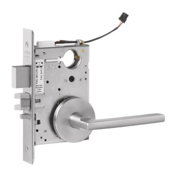
Page 4: Product Illustration
ML20900 ECL Series Mortise Lock ® ASSA ABLOY 4) Product Illustration ® Tools Required: • Phillips Screw Driver (Standard size) • Flat Blade Screw Driver (Standard size) • 1/8" Allen Wrench Copyright © 2014 Corbin Russwin, Inc. All rights reserved. -
Page 5: Installation Instructions
ML20900 ECL Series Mortise Lock ® ASSA ABLOY 5) Installation Instructions Verify Hand and Bevel of door. Illustrations shown are as viewed from the outside or secure side of opening. Left Hand Left Hand Right Hand Right Hand Hinges Left. - Page 6 ML20900 ECL Series Mortise Lock ® ASSA ABLOY 5) Installation Instructions (Continued) Handing of Lock Body Step 1) Move the red locking screw to Catch Plate side of lock body being locked (Fig. 1) Step 2) Push in latch then depress catch plate with screw driver (Fig.
- Page 7 ML20900 ECL Series Mortise Lock ® ASSA ABLOY 5) Installation Instructions (Continued) 4. Configuring the Fail Safe/Fail Secure DIP switch settings: Check Please note that the lock must be cycled once in order to change the fail safe/fail polarity: secure setting.
- Page 8 ML20900 ECL Series Mortise Lock ® ASSA ABLOY 5) Installation Instructions (Continued) Install Cylinder: a. Thread cylinder into lock body (Fig. 6a). Note: Make sure cylinder is oriented correctly (Fig. 6a1). b. Tighten cylinder clamp using 7/64” allen wrench (provided) (Fig. 6b).
- Page 9 ML20900 ECL Series Mortise Lock ® ASSA ABLOY 5) Installation Instructions (Continued) Inside Face of Door Install Standard Lever Trim. Refer to 7b on following pages for Trim: Step 1a Step 1b Outside Face of Door Inside Face of Door Outsdide Adapter Plate Fig.
- Page 10 ML20900 ECL Series Mortise Lock ® ASSA ABLOY 5) Installation Instructions (Continued) Step 4 Use Correct Spindle Orientation Inside Face of Door STANDARD MUSÉO Good Lever Fig. 4b L e v e r Fig. 4a Step 5 Align adjustment bolt with threaded hole in lever...
- Page 11 ML20900 ECL Series Mortise Lock ® ASSA ABLOY 5) Installation Instructions (Continued) Install Trim: Thread adapter plate hub into Align adapter plate hub with square lever and fully tighten hole in lever; keeping hub as tight as possible NOTE: Spindle can be...
- Page 12 ML20900 ECL Series Mortise Lock ® ASSA ABLOY 5) Installation Instructions (Continued) Set screw in hub faces away from door edge. INSIDE INSIDE Use Correct Spindle Orientation GOOD Lever Copyright © 2014 Corbin Russwin, Inc. All rights reserved. Reproduction in whole or in part without the express written...
- Page 13 ML20900 ECL Series Mortise Lock ® ASSA ABLOY 5) Installation Instructions (Continued) Install Armored Front: a. Tighten (2) screws through lock body. b. Attach armored front with two #8 x ¼” screws (Fig. 8). Outside Face of Door ® Tighten ®...
-
Page 14: Wiring Diagrams
ML20900 ECL Series Mortise Lock ® ASSA ABLOY 6) Wiring Diagrams Check Lock Schematics polarity: Verify + (red) wire Power Leads Power Leads x M92 For assistance, call 800-810-WIRE (Request to Exit) Red+ Red+ AC/DC AC/DC Black- Black- White Green... - Page 15 ML20900 ECL Series Mortise Lock ® ASSA ABLOY 6) Wiring Diagrams Tower Stairwell Access Control on Employee Entrance T o Fire Alarm 115VAC Power 115VAC Power Input Supply Input Supply Wires in Wires in Conduit Conduit (If Frames (If Frames...
-
Page 16: Mechanical Operational Check
ML20900 ECL Series Mortise Lock ® ASSA ABLOY 7) Mechanical Operational Check For mortise locks with cylinders: a. Insert key into cylinder and rotate: There should be no friction against lock case, wire harness or any other obstructions. b. The key will retract the latch: Key should rotate freely.
Need help?
Do you have a question about the ML20900 Series and is the answer not in the manual?
Questions and answers