Table of Contents
Advertisement
22630 North 17th Avenue
Phoenix, Arizona 85027
Raising the Standards
Technical Support: 800.626.7590
support@hesinnovations.com
www.hesinnovations.com
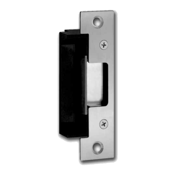
5000 series strike
Installation Instructions
©HES 2005
4019006.001 rev F
An ASSA ABLOY Group company
Advertisement
Table of Contents

Related Manuals for Assa Abloy HES 5000 Series


Summary of Contents for Assa Abloy HES 5000 Series
- Page 1 22630 North 17th Avenue Phoenix, Arizona 85027 Raising the Standards Technical Support: 800.626.7590 support@hesinnovations.com www.hesinnovations.com 5000 series strike Installation Instructions ©HES 2005 4019006.001 rev F An ASSA ABLOY Group company...
- Page 2 (not included, see page 3) description item quantity 5000 series faceplate Mounting screws #12-24 x 1/2 Faceplate screws #8-32 x 5/8 What tools would you recommend I use? *tool may differ for different applications An ASSA ABLOY Group company...
- Page 3 Connect the pigtail to the wires inside the frame by using the pg 21 pg 24 blue wire connectors. aluminum door 503B pg 24 Crimp connectors with pliers. pg 26 Refer to pages 13-26 for faceplate dimensions. An ASSA ABLOY Group company...
- Page 4 Insert violet and black wires coming from the strike into one blue wire connector, crimp with pliers. crimp one blue wire connector on each black and violet wire coming from the connector to prevent a short circuit. An ASSA ABLOY Group company...
- Page 5 Loosen screws, but do not remove them. Place trim enhancer on Move screws into fail safe position as shown. electric strike body. Tighten screws. Attach the trim enhancer to electric strike body using the provided trim enhancer screws An ASSA ABLOY Group company...
- Page 6 Connect the electric strike to the pigtail. Insert strike into frame. Tighten both mounting screws securely. 1/2” - Part Number: 5104-1/2 1” - Part Number: 5104-1 1-1/4” - Part Number: 5104-1-1/4 3” - Part Number: 5104-3 An ASSA ABLOY Group company...
- Page 7 HES offers a universal Metal Template Kit to simplify continue with Step 4 the installation procedure. Order the model 154-MTK by calling customer support at 800.626.7590. *Note: Frame example with ANSI 4 7/8” x 1 1/4” strike preparation An ASSA ABLOY Group company...
- Page 8 What should the cutout be? 501 faceplate option What are the faceplate dimensions? 31.8 1 1/4" 4 7/8" 85.7 3 3/8" 17.5 11/16" [2.3] [mm] 3/32" Inches [mm] Inches Cut frame according to the dimensions in the drawing. An ASSA ABLOY Group company...
- Page 9 Cut frame according to the dimensions in the drawing. [mm] Install the mounting tabs to the frame, but do not fully tighten mounting Inches tab screws.* After you install the strike, securely tighten the mounting tab screws. An ASSA ABLOY Group company...
- Page 10 Cut frame according to the dimensions in the drawing. Inches Install the mounting tabs to the frame, but do not fully tighten mounting tab screws.* After you install the strike, securely tighten the mounting tab screws. An ASSA ABLOY Group company...
- Page 11 Chisel out the recess dimensions within the frame. tab screws.* For wood applications pre-drill pilot hole for mounting points After you install the strike, securely tighten the mounting tab screws. with a #30 drill bit. An ASSA ABLOY Group company...
- Page 12 Cut frame according to the dimensions in the drawing. Install the mounting tabs to the frame, but do not fully tighten mounting [mm] tab screws.* Inches After you install the strike, securely tighten the mounting tab screws. An ASSA ABLOY Group company...
- Page 13 Install the mounting tabs to the frame, but do not fully tighten mounting 503B* [mm] tab screws.* Inches After you install the strike, securely tighten the mounting tab screws. * 503B bevel face R 1/8” An ASSA ABLOY Group company...
- Page 14 [mm] Inches Cut frame according to the dimensions in the drawing. Chisel out the recess dimensions within the frame. [mm] Inches For wood applications pre-drill pilot hole for mounting points with a #30 drill bit. An ASSA ABLOY Group company...
Need help?
Do you have a question about the HES 5000 Series and is the answer not in the manual?
Questions and answers