Table of Contents
Advertisement
Quick Links
Installation Instructions
8000/8300 Series Electric Strike
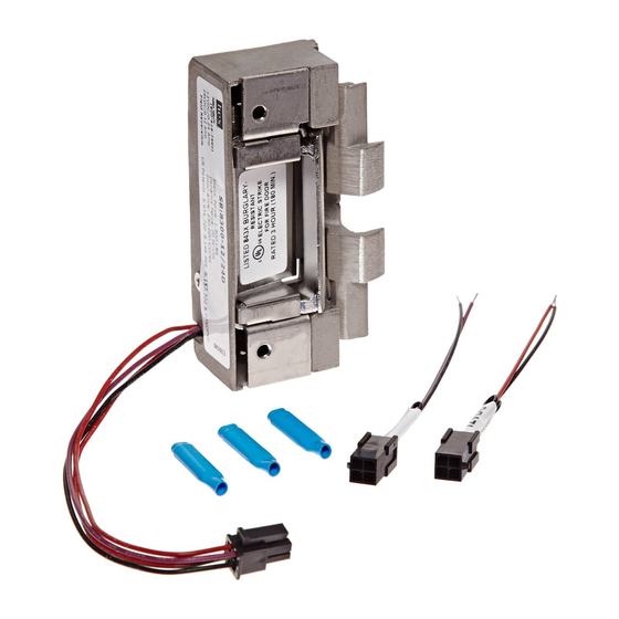
Product Components
1
2
1
Diagram 1: Electrical Specifications
ELECTRICAL RATINGS FOR SOLENOID
Resistance in Ohms
Amps
Solenoids are rated at +/- 10% indicated value.
*10% max duty cycle (2 min. max on time)
8000/8300 Electric Strike Body
Sticky Shims (optional use)
3
CONTINUOUS DUTY
INTERMITTENT DUTY*
12VDC
24VDC
12-16VAC
50
200
50
.24
.12
.24-.32
12 & 24 Volt Pigtails
3
MINIMUM WIRE GAUGE REQUIREMENTS
24VAC
200
200 feet or less
.12
200 - 300 feet
300 - 400 feet
HES, Inc.
22630 N. 17th Ave.
Phoenix, AZ 85027
800-626-7590
www.hesinnovations.com
2
SOLENOID VOLTAGE
12VDC
24VDC
18 gauge
20 gauge
16 gauge
18 gauge
14 gauge
16 gauge
1
Advertisement
Table of Contents

Related Manuals for Assa Abloy hes 8000 Series


Summary of Contents for Assa Abloy hes 8000 Series
- Page 1 HES, Inc. Installation Instructions 22630 N. 17th Ave. Phoenix, AZ 85027 800-626-7590 8000/8300 Series Electric Strike www.hesinnovations.com Product Components 12 & 24 Volt Pigtails 8000/8300 Electric Strike Body Sticky Shims (optional use) Diagram 1: Electrical Specifications ELECTRICAL RATINGS FOR SOLENOID CONTINUOUS DUTY INTERMITTENT DUTY* MINIMUM WIRE GAUGE REQUIREMENTS...
- Page 2 Installation Directions CAUTION! Before connecting any device at the installation site, verify input voltage using a multimeter. Many power supplies and low voltage transformers operate at higher levels than listed. Any input voltage exceeding 10% of the solenoid rating may cause severe damage to the unit and will void the warranty. Evaluate Opening 7.
- Page 3 Installation Diagrams DIAGRAM 3: FAIL SAFE TO FAIL SECURE DIAGRAM 4: LATCHBOLT MONITOR LBM WIRING Fail Safe* White Common Loosen screws, but do not Orange Normally Open remove them Green Normally Closed Move screws to the Fail Safe position as shown Tighten screws White *Fire rating only applies to Fail...
- Page 4 Cutout Templates Inches [mm] 8000/8300 with 801 Faceplate 1-1/4” X 4-7/8” Square Corner Faceplate ANSI Metal Jamb Installations 1-1/4" [32] 4-7/8" [124] 4-1/8" [105] 3-3/8" [86] 1/8" [3] DIAGRAM 8: WIRE DRILLING 3/16" [4.8] NOTE: The 8000/8300 electric strike with 801faceplate will fit right into most standard ANSI A115.2, 1”...
- Page 5 Cutout Templates Inches [mm] 8000/8300 with 801A Faceplate 1-1/4” x 4-7/8” Radius Corner Faceplate Aluminum Jamb Installations 1-1/4"[32] 4-7/8" [124] 4-1/8" [105] 3-3/8" [86] R 5/32" [4] 1/8" [3] 8000/8300 with 802 Faceplate 1-7/16” x 7-15/16” Radius Corner Faceplate Aluminum and Wood Jamb Installations 1-7/16"...
- Page 6 Cutout Template Inches [mm] 8000/8300 with 803 Faceplate 1-1/4” x 6-7/8” Radius Corner Faceplate Aluminum Jamb Installations 1-1/4" [32] 6-7/8" [175] 6-1/8" [156] 3-3/8" [86] 1/8" [3] 8000/8300 with 805 Faceplate 1-3/8” x 9” Radius Corner Faceplate Aluminum or Wood Jamb Installations 1-3/8"...
Need help?
Do you have a question about the hes 8000 Series and is the answer not in the manual?
Questions and answers