Table of Contents
Advertisement
Quick Links
Advertisement
Table of Contents
Troubleshooting

Subscribe to Our Youtube Channel
Related Manuals for Supermicro SuperServer SYS-110A-16C-RN10SP


Summary of Contents for Supermicro SuperServer SYS-110A-16C-RN10SP
- Page 1 SuperServer ® SYS-110A-16C-RN10SP SYS-110A-24C-RN10SP USER’S MANUAL Revision 1.0a...
- Page 2 State of California, USA. The State of California, County of Santa Clara shall be the exclusive venue for the resolution of any such disputes. Supermicro's total liability for all claims will not exceed the price paid for the hardware product.
- Page 3 If you have any questions, please contact our support team at: support@supermicro.com This manual may be periodically updated without notice. Please check the Supermicro website for possible updates to the manual revision level. Secure Data Deletion A secure data deletion tool designed to fully erase all data from storage devices can be found on our website: https://www.supermicro.com/about/policies/disclaimer.cfm?url=/wdl/utility/...
-
Page 4: Table Of Contents
Contents Contents Chapter 1 Introduction 1.1 Overview ..........................9 1.2 System Features ........................10 Front View .........................10 Control Panel .........................11 Rear View ..........................12 1.3 System Architecture ......................13 Main Components ......................13 1.4 Motherboard Layout ......................14 Quick Reference Table ......................15 Motherboard Block Diagram .....................17 Chapter 2 Server Installation 2.1 Overview ..........................18 2.2 Preparing for Setup ......................18... - Page 5 Contents 3.3 Static-Sensitive Devices ......................28 Precautions ........................28 3.4 Memory ..........................29 DIMM Module Population Configuration ................29 DIMM Installation ......................30 DIMM Removal .........................30 3.5 Motherboard Battery ......................31 M.2 Card Installation ......................32 3.6 Chassis Components ......................33 PCI Expansion Cards ......................33 Storage Drives ........................36 Installing 2.5"...
- Page 6 Contents Website ..........................65 Direct Links for the SYS-110A-16C/24C-RN10SP System ...........65 Direct Links for General Support and Information ............65 7.2 Baseboard Management Controller (BMC) ................66 7.3 Troubleshooting Procedures .....................67 General Technique ......................67 No Power ..........................67 No Video ...........................68 System Boot Failure ......................68 Memory Errors ........................68 Losing the System Setup Configuration ................68 When the System Becomes Unstable ................68...
- Page 7 San Jose, CA 95131 U.S.A. Tel: +1 (408) 503-8000 Fax: +1 (408) 503-8008 Email: marketing@supermicro.com (General Information) Sales-USA@supermicro.com (Sales Inquiries) Government_Sales-USA@supermicro.com (Gov. Sales Inquiries) support@supermicro.com (Technical Support) RMA@supermicro.com (RMA Support) Webmaster@supermicro.com (Webmaster) Website: www.supermicro.com Europe Address: Super Micro Computer B.V.
-
Page 8: Chapter 1 Introduction
1U (W x H x D) 17.2 x 1.7 x 9.8in (437 x 43 x 249mm) A Quick Reference Guide can be found on the product page of the Supermicro website. The following safety models associated with SYS-110A-16C/24C-RN10SP have been certified as... -
Page 9: System Features
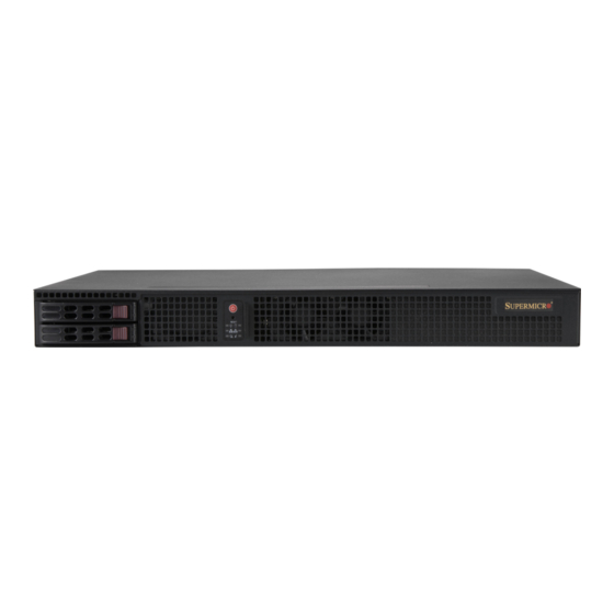
Chapter 1: Introduction 1.2 System Features The following views of the system display the main features. Refer to Appendix B for additional specifications. Front View Figure 1-1. Front View System Features: Front Item Feature Description Rack Ear Brackets Secures the server to the rack Solid-State Drives Two hot-swap 2.5"... -
Page 10: Control Panel
Chapter 1: Introduction Control Panel Figure 1-3. Control Panel Control Panel Features Item Feature Description The main power switch applies or removes primary power from the power supply Power button to the server but maintains standby power. Reset Button System Reset. Indicates power is being supplied to the system power supply units. -
Page 11: Rear View
Chapter 1: Introduction Rear View Figure 1-4. System: Rear View System Features: Rear Item Feature Description Power Supplies 300W AC redundant power supplies I/O Rear Panel Rear panel for I/O devices supported on the motherboard (see Chapter PCIe Slot One HHHL PCIe expansion slot Security slot Kensington®... -
Page 12: System Architecture
Chapter 1: Introduction 1.3 System Architecture This section shows the locations of the system's main components. Main Components Processor DIMM Slots Hot-Swappable 2.5" Power Supply Modules System Fans Figure 1-5. Main Component Locations... -
Page 13: Motherboard Layout
Chapter 1: Introduction 1.4 Motherboard Layout Below is a layout of the A3SSV-16C/24C-SPLN10F motherboard with jumper, connector and LED locations shown. See the table on the following page for descriptions. For detailed descriptions, pinout information and jumper settings, refer to Chapter 4 or the Motherboard... -
Page 14: Quick Reference Table
Chapter 1: Introduction Quick Reference Table Jumper Description Default Setting JBM1 Disable IPMI Share LAN Pins 1-2 Open: Enabled JBM2 Disable IPMI Dedicated LAN Pins 1-2 Open: Enabled JBT1 CMOS Clear Open: Normal JPF1 Power Force On Pins 1-2: ATX mode Pins 2-3: Force PS-ON mode (Default) JPG1 Onboard VGA Enable/Disable... - Page 15 Chapter 1: Introduction Connector Description JPH1 4-pin Power Connector (for one HDD system) Power Supply SMBus I C Header JPV1 8-pin 12V DC Power Connector JPW1 24-pin ATX Power Connector JRT3 Thermal Diode 1 JSD1 SATA DOM Power Connector JSDP1 Software-Defined Pins for LAN5–LAN6 JSDP2 Software-Defined Pins LAN1–LAN4...
-
Page 16: Motherboard Block Diagram
Chapter 1: Introduction Motherboard Block Diagram CPLD SMBUS2 LCMXO2-1200HC AST2500 COM1/2 HEADER FAN X5 UART1/2 TACHOMETER RTL8211F RJ45 RGMII2 GIGALAN SVID VR13 HSIO[14],PCIe X1 USB 2.0[2] ESPI PCIe 3.0_x4 CPU, PCIe x4 PCIe X4 SLOT 6 DDR4 (CHA) DIMMA1,A2 8GT/s Intel SoC 2933MHz PCIe 3.0_x8... -
Page 17: Chapter 2 Server Installation
Chapter 2: Server Installation Chapter 2 Server Installation 2.1 Overview This chapter provides advice and instructions for mounting your system in a server rack. If your system is not already fully integrated with system memory etc., refer to Chapter 3 details on installing those specific components. -
Page 18: Server Precautions
Chapter 2: Server Installation • Always make sure the rack is stable before extending a server or other component from the rack. • You should extend only one server or component at a time - extending two or more simul- taneously may cause the rack to become unstable. -
Page 19: Mechanical Loading
Chapter 2: Server Installation Mechanical Loading Equipment should be mounted into a rack so that a hazardous condition does not arise due to uneven mechanical loading. Circuit Overloading Consideration should be given to the connection of the equipment to the power supply circuitry and the effect that any possible overloading of circuits might have on overcurrent protection and power supply wiring. -
Page 20: Installing The Chassis Into The Rack
Chapter 2: Server Installation 2.3 Installing the Chassis into the Rack This section provides information on installing the CSE-506TS-R301P chassis into a rack unit. Due to the variety of rack units on the market, the assembly procedure might differ slightly. Also refer to the installation instructions that came with the rack unit you are using. -
Page 21: Mid-Mount Telco Rack
Chapter 2: Server Installation Mid-Mount Telco Rack The CSE-506TS-R301P supports Telco Rack installation. The compact design allows it to be installed into a Telco rack without the use of rails. Figure 2-2. Installing the Server into a Rack Note: Figures are for illustrative purposes only. Servers should always be installed in racks from the bottom up. -
Page 22: Standard Rack With A Fixed Rail Kit
Chapter 2: Server Installation Standard Rack with a Fixed Rail Kit The chassis can be mounted in a rack using a fixed rail kit (optional, MCP-290-50404-0N). Figure 2-3. Fixed Rails Installing the Chassis on Fixed Rails into a Standard Rack 1. - Page 23 Chapter 2: Server Installation 1. Attach the rails to the chassis using three screws through the holes in each front bracket to secure a bracket to each side of the chassis. Figure 2-5. Rails Attached to the Chassis 2. Install the chassis on rails into the rack, using three screws through each front bracket and two screws through each rear bracket to secure the rails to the rack.
- Page 24 Chapter 2: Server Installation Figure 2-8. Installing the Server on Fixed Rails into a Rack Note: Figures are for illustrative purposes only. Servers should always be installed in racks from the bottom up.
-
Page 25: Chapter 3 Maintenance And Component Installation
Chapter 3: Maintenance and Component Installation Chapter 3 Maintenance and Component Installation This chapter provides instructions on installing and replacing main system components. To prevent compatibility issues, only use components that match the specifications and/or part numbers given. Installation or replacement of most components require that power first be removed from the system. -
Page 26: Accessing The System
Chapter 3: Maintenance and Component Installation 3.2 Accessing the System Removing the Chassis Cover 1. Power down the system as described in Section 3.1. 2. Remove two screws from the chassis top and two screws from each chassis side. 3. Lift the cover up and off the chassis. Caution: Do not operate the server without the cover in place. -
Page 27: Static-Sensitive Devices
Chapter 3: Maintenance and Component Installation 3.3 Static-Sensitive Devices Electrostatic Discharge (ESD) can damage electronic components. To avoid damaging your motherboard, it is important to handle it very carefully. The following measures are generally sufficient to protect the system PCBs from ESD. Precautions •... -
Page 28: Memory
Chapter 3: Maintenance and Component Installation 3.4 Memory The A3SSV-16C/24C-SPLN10F motherboard supports up to 256GB of ECC RDIMM or 64GB of Non-EC/ECC UDIMM DDR4 memory in four memory slots. Refer to the tables below for the recommended DIMM population order and additional memory information. DIMM Module Population Configuration For optimal memory performance, follow the table below when populating memory. -
Page 29: Dimm Installation
Chapter 3: Maintenance and Component Installation DIMM Installation PRESS FIT UIDLED1 JUIDB 1. Insert the desired number of DIMMs into JBM2 SRW2 JBM1 AST2500 the memory slots, starting with DIMMA1, USB 0/1 (3.0) MARVELL IPMI LAN 88E1543 LAN 1-4 LAN 7-10 LEDM1 JGP1 JPCIE6... -
Page 30: Motherboard Battery
Chapter 3: Maintenance and Component Installation 3.5 Motherboard Battery The motherboard uses non-volatile memory to retain system information when system power is removed. This memory is powered by a lithium battery residing on the motherboard. Replacing the Battery Begin by the removing the top cover from the system. 1. -
Page 31: Card Installation
Chapter 3: Maintenance and Component Installation M.2 Card Installation The A3SSV-16C/24C-SPLN10F supports three M.2 connectors. One M.2 M-Key PCIe 2.0 x4/ SATA 2.0/USB 2.0, 2242/2280/22110 connector, one M.2 B-Key PCIe 2.0 x2/SATA 2.0/USB 3.0, 2242/3042/2280 connector, and one M.2 E-Key PCIe 2.0 x1/USB 2.0, 2230 connector. To install an M.2 card, first locate the connector and the standoff on the motherboard. -
Page 32: Chassis Components
Chapter 3: Maintenance and Component Installation 3.6 Chassis Components This section provides instructions on installing and replacing system components. To assure compatibility, only use components that match the specifications or part numbers given. PCI Expansion Cards The system supports a riser card that allows a half-length expansion card to fit inside the chassis. - Page 33 Chapter 3: Maintenance and Component Installation Assemble the PCIe Expansion Card, Riser Card, and Brackets 1. Remove power as described in Section 3.1 and remove the chassis cover. 2. Remove the PCIe I/O shield. 3. Remove the PCIe slot bracket. 4.
- Page 34 Chapter 3: Maintenance and Component Installation Figure 3-5. Installing the Expansion Card Assembly Installing the Expansion Card Assembly 1. Insert the assembly into the motherboard and align with the chassis rear. 2. Secure the assembly to the chassis with screws. Figure 3-6.
-
Page 35: Storage Drives
Chapter 3: Maintenance and Component Installation Storage Drives The chassis supports two 2.5" hot-swappable hard disk drives. Only enterprise-level hard drives are recommended. Note: The hard drives in your chassis may look slightly different from the ones shown in this manual. Installing 2.5"... - Page 36 Chapter 3: Maintenance and Component Installation 1. Install the drive into the drive tray and secure it with screws. Screws Screws Figure 3-9. Installing Storage Drives 2. Insert the drive into the chassis and lock the drive tray. Lock Figure 3-10. Installing the Hot Swappable Drive...
-
Page 37: System Cooling
Chapter 3: Maintenance and Component Installation System Cooling The SuperServer SYS-110A-16C/24C-RN10SP is cooled by up to three fans and an air shroud. System Fans The fans can adjust their speed according to the heat level sensed in the system, which results in more efficient and quieter fan operation. - Page 38 Chapter 3: Maintenance and Component Installation 5. Remove the failed fan from the fan tray. 6. In the fan tray, insert a new fan with the fan guard facing the chassis rear. 7. Reinstall the chassis cover. 8. Reconnect the power cord and power up the system. 9.
-
Page 39: Checking The Server Air Flow
Chapter 3: Maintenance and Component Installation Checking the Server Air Flow • Make sure there are no objects to obstruct airflow in and out of the server. • Use only recommended server parts. • Make sure no wires or foreign objects obstruct air flow through the chassis. Pull all excess cabling out of the airflow path or use shorter cables. -
Page 40: Power Supply
The CSE-506TS-R301P chassis has two 300W AC hot-swappable redundant power supplies. The power supplies are auto-switching capable. If replacing a power supply, the system does not need to be powered down. New units can be ordered directly from Supermicro or authorized distributors. - Page 41 Chapter 3: Maintenance and Component Installation Release Tab Handle Figure 3-13. Removing the Power Supply...
-
Page 42: Chapter 4 Motherboard Connections
Chapter 4: Motherboard Connections Chapter 4 Motherboard Connections This section describes the connections on the motherboard and provides pinout definitions. Note that depending on how the system is configured, not all connections are required. The LEDs on the motherboard are also described here. A motherboard layout indicating component locations may be found in Chapter 1. - Page 43 Chapter 4: Motherboard Connections HDD Power Connector JPH1 is a 4-pin power connector for HDD use. It provides power from the motherboard to the onboard HDDs. 4-pin HDD Power Pin Definitions Pin# Definition...
-
Page 44: Headers And Connectors
Chapter 4: Motherboard Connections 4.2 Headers and Connectors Fan Headers The A3SSV-16C/24C-SPLN10F has five 4-pin fan headers (FAN1 - FAN3, FANA, FANB). These headers are backwards-compatible with the traditional 3-pin fans. However, fan speed control is available for 4-pin fans only by Thermal Management via the IPMI 2.0 interface. Refer to the table below for pin definitions. - Page 45 Chapter 4: Motherboard Connections General Purpose I/O Header JGP1 is a 10-pin general purpose I/O header. Each pin can be configured to be an input or output pin. The GPIO is controlled via the PCA9554 8-bit GPIO expansion. The base address is 0xF040(D31:F4).
- Page 46 Port 80 connection. Use this header to enhance system performance and data security. Refer to the table below for pin definitions. Please go to the following link for more information on the TPM: http://www.supermicro.com/manuals/other/TPM.pdf. Trusted Platform Module Header Pin Definitions...
- Page 47 Chapter 4: Motherboard Connections M.2 Slot The A3SSV-8C/16C/24C-SPLN10F motherboard has three M.2 slots (JMD1, JMD2, and JMD3). M.2 was formerly known as Next Generation Form Factor (NGFF) and serves to replace mini PCIe. M.2 allows for a variety of card sizes, increased functionality, and spatial efficiency.
- Page 48 JFPCLED1 is the 1GbE RJ45 link and activity LED header. Attach a cable from this header to the Supermicro LED board (Part Number: FPB-FPE300-LED10) to display the status of the RJ45 LAN link and activity LED. The LED board FPB-FPE300-LED10 is reserved for use on the E300 chassis.
-
Page 49: Input/Output Ports
Chapter 4: Motherboard Connections 4.3 Input/Output Ports See the figure below for the locations and descriptions of the I/O ports on the rear of the motherboard. Figure 4-1. I/O Port Locations and Definitions Rear I/O Ports Description Description Description IPMI LAN LAN4 LAN9 USB1 (USB3.0) - Page 50 Chapter 4: Motherboard Connections COM Headers The motherboard has two front accessible COM headers (COM1 and COM2) to provide serial connections. COM Header Pin Definitions Pin# Definition Pin# Definition Ground Universal Serial Bus (USB) Ports There are two USB 3.0 ports (USB0/1) on the back panel I/O and one USB header (USB2/3). The onboard header can be used to provide front side USB access with a cable (not included).
- Page 51 Note: UID can also be triggered via IPMI on the motherboard. For more information on IPMI, please refer to the IPMI User's Guide posted on our website at https://www.supermicro.com/ support/manuals/. UID Button...
-
Page 52: Jumpers
Chapter 4: Motherboard Connections 4.4 Jumpers How Jumpers Work To modify the operation of the motherboard, jumpers can be used to choose between optional settings. Jumpers create shorts between two pins to change the function of the connector. Pin 1 is identified with a square solder pad on the printed circuit board. Refer to the diagram below for an example of jumping pins 1 and 2. - Page 53 Chapter 4: Motherboard Connections LAN Port Enable/Disable Change the setting of jumpers JPL1 for LAN1–4. LAN Enable/Disable Jumper Settings Jumper Setting Definition Pins 1-2 Enabled (Deafult) Pins 2-3 Disabled Watch Dog JWD1 controls the Watch Dog function. Watch Dog is a monitor that can reboot the system when a software application hangs.
- Page 54 Chapter 4: Motherboard Connections VGA Enable/Disable Use jumper JPG1 to enable or disable the onboard VGA port. Refer to the table below for jumper settings. VGA Enable/Disable Jumper Settings Jumper Setting Definition Pins 1-2 Enabled (Default) Pins 2-3 Disabled IPMI Share LAN Enable/Disable Set the JBM1 jumper to enabled to share i350 LAN with IPMI.
-
Page 55: Led Indicators
Chapter 4: Motherboard Connections 4.5 LED Indicators LAN LEDs Eight RJ45 LAN ports and two SFP LAN ports are located on the I/O back panel. Each Ethernet LAN port has two LEDs. One LED indicates activity, while the other Link LED may be green, amber, or off to indicate the speed of the connection. -
Page 56: Front Control Panel
JF1 contains header pins for various buttons and indicators that are normally located on a control panel at the front of the chassis. These connectors are designed specifically for use with Supermicro chassis. See the figure below for the descriptions of the front control panel buttons and LED indicators. - Page 57 Chapter 4: Motherboard Connections NIC1/NIC2 (LAN1/LAN2) The NIC (Network Interface Controller) LED connection for LAN port 1 is located on pins 11 and 12 of JF1, and LAN port 2 is on pins 9 and 10. Attach the NIC LED cables here to display network activity.
-
Page 58: Chapter 5 Software
1. Create a method to access the Microsoft Windows installation ISO file. That can be a USB flash, media drive, or the BMC KVM console. 2. Retrieve the proper RST/RSTe driver. Go to the Supermicro web page for your motherboard and click on "Download the Latest Drivers and Utilities", select the proper driver, and copy it to a USB flash drive. - Page 59 Chapter 5: Software 4. During Windows Setup, continue to the dialog where you select the drives on which to install Windows. If the disk you want to use is not listed, click on “Load driver” link at the bottom left corner. Figure 5-2.
-
Page 60: Driver Installation
The Supermicro website contains drivers and utilities for your system at https://www. supermicro.com/wdl/driver. Some of these must be installed, such as the chipset driver. After accessing the website, go into the CDR_Images (in the parent directory of the above link) and locate the ISO file for your motherboard. Download this file to a USB flash drive or media drive (you may also use a utility to extract the ISO file if preferred). -
Page 61: Superdoctor ® 5
5.3 SuperDoctor ® The Supermicro SuperDoctor 5 is a program that functions in a command-line or web-based interface for Windows and Linux operating systems. The program monitors such system health information as CPU temperature, system voltages, system power consumption, fan speed, and provides alerts via email or Simple Network Management Protocol (SNMP). -
Page 62: Bmc
There are several BIOS settings that are related to BMC. For general documentation and information on BMC, visit our website at: www.supermicro.com/en/solutions/management-software/bmc-resources BMC ADMIN User Password For security, each system is assigned a unique default BMC password for the ADMIN user. -
Page 63: Chapter 6 Optional Components
Chapter 6: Optional Components Chapter 6 Optional Components This chapter describes optional system components and installation procedures. 6.1 Optional Parts List Optional Parts List Description Part Number Fix Rail Kit Set MCP-290-50404-0N... -
Page 64: Chapter 7 Troubleshooting And Support
Chapter 7 Troubleshooting and Support 7.1 Information Resources Website A great deal of information is available on the Supermicro website, supermicro.com. Figure 7-1. Supermicro Website • Specifications for servers and other hardware are available by clicking the Products option. •... -
Page 65: Baseboard Management Controller (Bmc)
Security Center for recent security notices Supermicro Phone and Addresses 7.2 Baseboard Management Controller (BMC) The system supports the Baseboard Management Controller (BMC). BMC is used to provide remote access, monitoring and management. There are several BIOS settings that are related to BMC. -
Page 66: Troubleshooting Procedures
Chapter 7: Troubleshooting and Support 7.3 Troubleshooting Procedures Use the following procedures to troubleshoot your system. If you have followed all of the procedures below and still need assistance, refer to the Technical Support Procedures Returning Merchandise for Service section(s) in this chapter. Power down the system before changing any non hot-swap hardware components. -
Page 67: No Video
• Memory: Make sure that the memory modules are supported. Refer to the product page on our website at www.supermicro.com. Test the modules using memtest86 or a similar utility. • Storage drives: Make sure that all drives work properly. Replace if necessary. - Page 68 Also check the Control panel Overheat LED. • Adequate power supply: Make sure that the power supply provides adequate power to the system. Make sure that all power connectors are connected. Refer to the Supermicro website for the minimum power requirements. •...
-
Page 69: Crash Dump Using Bmc
In the event of a processor internal error (IERR) that crashes your system, you may want to provide information to support staff. You can download a crash dump of status information using BMC. The BMC manual is available at https://www.supermicro.com/en/solutions/ management-software/bmc-resources. Check BMC Error Log 1. -
Page 70: Uefi Bios Recovery
Warning: Do not upgrade the BIOS unless your system has a BIOS-related issue. Flashing the wrong BIOS can cause irreparable damage to the system. In no event shall Supermicro be liable for direct, indirect, special, incidental, or consequential damages arising from a BIOS update. - Page 71 USB device or a writable CD/DVD. Note 1: If you cannot locate the "Super.ROM" file in your drive disk, visit our website at www.supermicro.com to download the BIOS package. Extract the BIOS binary image into a USB flash device and rename it "Super.ROM" for the BIOS recovery use.
- Page 72 Chapter 7: Troubleshooting and Support Note: At this point, you may decide if you want to start the BIOS recovery. If you decide to proceed with BIOS recovery, follow the procedures below. 4. When the screen as shown above displays, use the arrow keys to select the item "Proceed with flash update"...
- Page 73 Chapter 7: Troubleshooting and Support 7. Press <Del> continuously during system boot to enter the BIOS Setup utility. From the top of the tool bar, select Boot to enter the submenu. From the submenu list, select Boot Option #1 as shown below. Then, set Boot Option #1 to [UEFI AP:UEFI: Built-in EFI Shell]. Press <F4>...
- Page 74 Chapter 7: Troubleshooting and Support Note: Do not interrupt this process until the BIOS flashing is complete. 9. The screen above indicates that the BIOS update process is complete. When you see the screen above, unplug the AC power cable from the power supply, clear CMOS, and plug the AC power cable in the power supply again to power on the system.
-
Page 75: Cmos Clear
Chapter 7: Troubleshooting and Support 7.6 CMOS Clear JBT1 is used to clear CMOS, which will also clear any passwords. Instead of pins, this jumper consists of contact pads to prevent accidentally clearing the contents of CMOS. To Clear CMOS 1. -
Page 76: Where To Get Replacement Components
7.7 Where to Get Replacement Components If you need replacement parts for your system, to ensure the highest level of professional service and technical support, purchase exclusively from our Supermicro Authorized Distributors/System Integrators/Resellers. A list can be found at: http://www.supermicro.com. -
Page 77: Vendor Support Filing System
For issues related to Red Hat Enterprise Linux, since it is a subscription based OS, contact your account representative. 7.9 Feedback Supermicro values your feedback as we strive to improve our customer experience in all facets of our business. Please email us at techwriterteam@supermicro.com to provide feedback on our manuals. -
Page 78: Appendix A Standardized Warning Statements For Ac Systems
Supermicro's Technical Support department for assistance. Only certified technicians should attempt to install or configure components. Read this appendix in its entirety before installing or configuring components in the Supermicro chassis. These warnings may also be found on our website at http://www.supermicro.com/about/... - Page 79 Appendix A: Standardized Warning Statements Warnung WICHTIGE SICHERHEITSHINWEISE Dieses Warnsymbol bedeutet Gefahr. Sie befinden sich in einer Situation, die zu Verletzungen führen kann. Machen Sie sich vor der Arbeit mit Geräten mit den Gefahren elektrischer Schaltungen und den üblichen Verfahren zur Vorbeugung vor Unfällen vertraut. Suchen Sie mit der am Ende jeder Warnung angegebenen Anweisungsnummer nach der jeweiligen Übersetzung in den übersetzten Sicherheitshinweisen, die zusammen mit diesem Gerät ausgeliefert wurden.
- Page 80 SuperServer 110A-16C/24C-RN10SP User's Manual . ٌ ا ك ً ف حالة و ٌ يك أى تتسبب ف اصابة جسذ ة ٌ هذا الزهز ع ٌ خطز !تحذ ز قبل أى تعول عىل أي هعذات،يك عىل علن بالوخاطز ال ا ٌجوة عي الذوائز ٍ...
- Page 81 Appendix A: Standardized Warning Statements Warnung Vor dem Anschließen des Systems an die Stromquelle die Installationsanweisungen lesen. ¡Advertencia! Lea las instrucciones de instalación antes de conectar el sistema a la red de alimentación. Attention Avant de brancher le système sur la source d'alimentation, consulter les directives d'installation. .יש...
- Page 82 SuperServer 110A-16C/24C-RN10SP User's Manual Warnung Dieses Produkt ist darauf angewiesen, dass im Gebäude ein Kurzschluss- bzw. Überstromschutz installiert ist. Stellen Sie sicher, dass der Nennwert der Schutzvorrichtung nicht mehr als: 250 V, 20 A beträgt. ¡Advertencia! Este equipo utiliza el sistema de protección contra cortocircuitos (o sobrecorrientes) del edificio.
- Page 83 Appendix A: Standardized Warning Statements Power Disconnection Warning Warning! The system must be disconnected from all sources of power and the power cord removed from the power supply module(s) before accessing the chassis interior to install or remove system components. 電源切断の警告...
- Page 84 SuperServer 110A-16C/24C-RN10SP User's Manual يجب فصم اننظاو من جميع مصادر انطاقت وإ ز انت سهك انكهرباء من وحدة امداد انطاقت قبم انىصىل إىن امنناطق انداخهيت نههيكم نتثبيج أو إ ز انت مكىناث الجهاز 경고! 시스템에 부품들을 장착하거나 제거하기 위해서는 섀시 내부에 접근하기 전에 반드시 전원 공급장치로부터...
- Page 85 Appendix A: Standardized Warning Statements Attention Il est vivement recommandé de confier l'installation, le remplacement et la maintenance de ces équipements à des personnels qualifiés et expérimentés. !אזהרה .צוות מוסמך בלבד רשאי להתקין, להחליף את הציוד או לתת שירות עבור הציוד واملدربيه...
- Page 86 SuperServer 110A-16C/24C-RN10SP User's Manual Warnung Diese Einheit ist zur Installation in Bereichen mit beschränktem Zutritt vorgesehen. Der Zutritt zu derartigen Bereichen ist nur mit einem Spezialwerkzeug, Schloss und Schlüssel oder einer sonstigen Sicherheitsvorkehrung möglich. ¡Advertencia! Esta unidad ha sido diseñada para instalación en áreas de acceso restringido. Sólo puede obtenerse acceso a una de estas áreas mediante la utilización de una herramienta especial, cerradura con llave u otro medio de seguridad.
- Page 87 Appendix A: Standardized Warning Statements Battery Handling Warning! There is the danger of explosion if the battery is replaced incorrectly. Replace the battery only with the same or equivalent type recommended by the manufacturer. Dispose of used batteries according to the manufacturer's instructions 電池の取り扱い...
- Page 88 SuperServer 110A-16C/24C-RN10SP User's Manual هناك خطر من انفجار يف حالة اسحبذال البطارية بطريقة غري صحيحة فعليل اسحبذال البطارية فقط بنفس النىع أو ما يعادلها مام أوصث به الرشمة املصنعة جخلص من البطاريات املسحعملة وفقا لحعليامت الرشمة الصانعة 경고! 배터리가 올바르게 교체되지 않으면 폭발의 위험이 있습니다. 기존 배터리와 동일하거나 제 조사에서...
- Page 89 Appendix A: Standardized Warning Statements ¡Advertencia! Puede que esta unidad tenga más de una conexión para fuentes de alimentación. Para cortar por completo el suministro de energía, deben desconectarse todas las conexiones. Attention Cette unité peut avoir plus d'une connexion d'alimentation. Pour supprimer toute tension et tout courant électrique de l'unité, toutes les connexions d'alimentation doivent être débranchées.
- Page 90 SuperServer 110A-16C/24C-RN10SP User's Manual Backplane Voltage Warning! Hazardous voltage or energy is present on the backplane when the system is operating. Use caution when servicing. バックプレーンの電圧 システムの稼働中は危険な電圧または電力が、 バックプレーン上にかかっています。 修理する際には注意く ださい。 警告 当系统正在进行时,背板上有很危险的电压或能量,进行维修时务必小心。 警告 當系統正在進行時,背板上有危險的電壓或能量,進行維修時務必小心。 Warnung Wenn das System in Betrieb ist, treten auf der Rückwandplatine gefährliche Spannungen oder Energien auf.
- Page 91 Appendix A: Standardized Warning Statements هناك خطز مه التيار الكهزبايئ أوالطاقة املىجىدة عىل اللىحة عندما يكىن النظام يعمل كه حذ ر ا عند خدمة هذا الجهاس 경고! 시스템이 동작 중일 때 후면판 (Backplane)에는 위험한 전압이나 에너지가 발생 합니다. 서비스 작업 시 주의하십시오. Waarschuwing Een gevaarlijke spanning of energie is aanwezig op de backplane wanneer het systeem in gebruik is.
- Page 92 SuperServer 110A-16C/24C-RN10SP User's Manual תיאום חוקי החשמל הארצי !אזהרה .התקנת הציוד חייבת להיות תואמת לחוקי החשמל המקומיים והארציים تركيب املعدات الكهربائية يجب أن ميتثل للقىاويه املحلية والىطىية املتعلقة بالكهرباء 경고! 현 지역 및 국가의 전기 규정에 따라 장비를 설치해야 합니다. Waarschuwing Bij installatie van de apparatuur moet worden voldaan aan de lokale en nationale elektriciteitsvoorschriften.
- Page 93 Appendix A: Standardized Warning Statements Attention La mise au rebut ou le recyclage de ce produit sont généralement soumis à des lois et/ou directives de respect de l'environnement. Renseignez-vous auprès de l'organisme compétent. סילוק המוצר !אזהרה .סילוק סופי של מוצר זה חייב להיות בהתאם להנחיות וחוקי המדינה التخلص...
- Page 94 SuperServer 110A-16C/24C-RN10SP User's Manual Warnung Gefährlich Bewegende Teile. Von den bewegenden Lüfterblätter fern halten. Die Lüfter drehen sich u. U. noch, wenn die Lüfterbaugruppe aus dem Chassis genommen wird. Halten Sie Finger, Schraubendreher und andere Gegenstände von den Öffnungen des Lüftergehäuses entfernt.
- Page 95 Verbindungskabeln, Stromkabeln und/oder Adapater, die Ihre örtlichen Sicherheitsstandards einhalten. Der Gebrauch von anderen Kabeln und Adapter können Fehlfunktionen oder Feuer verursachen. Die Richtlinien untersagen das Nutzen von UL oder CAS zertifizierten Kabeln (mit UL/CSA gekennzeichnet), an Geräten oder Produkten die nicht mit Supermicro gekennzeichnet sind.
- Page 96 .قيرح وأ لطع يف ببستي دق ىرخأ تالوحمو تالباك يأ مادختسا .ميلسلا سباقلاو لصوملا مجح لبق نم ةدمتعملا تالباكلا مادختسا تادعملاو ةيئابرهكلا ةزهجألل ةمالسلا نوناق رظحيUL وأCSA ( ةمالع لمحت يتلاوUL/CSA) لبق نم ةددحملاو ةينعملا تاجتنملا ريغ ىرخأ تادعم يأ عمSupermicro.
- Page 97 사항을 준수하여 제공되거나 지정된 연결 혹은 구매 케이블, 전원 케이블 및 AC 어댑터를 사용하십시오. 다른 케이블이나 어댑터를 사용하면 오작동이나 화재가 발생할 수 있습니다. 전기 용품 안전법은 UL 또는 CSA 인증 케이블 (코드에 UL / CSA가 표시된 케이블)을 Supermicro 가 지정한 제품 이외의 전기 장치에 사용하는 것을 금지합니다. Stroomkabel en AC-Adapter...
-
Page 98: Appendix B System Specifications
Appendix B: System Specifications Appendix B System Specifications Processors Single Intel® Atom P5000 series processor, with up to 24 cores at a 83W TDP Chipset System on Chip BIOS 32 Mb AMI UEFI BIOS ® UEFI 2.7, ACPI 6.0 or later, and SMBIOS 3.0 or later Memory Supports up to 256GB of RDIMM or 64GB of Non-ECC/ECC UDIMM DDR4 memory in four slots SYS-110A-16C-RN10SP: DDR4 2667MT/s, SYS-110A-24C-RN10SP: DDR4 2933MT/s... - Page 99 Appendix B: System Specifications Power Supply 80Plus Gold level SYS-110A-16C-RN10SP; Model: PWS-301P-1R, 300 W redundant module, 300W: 100-240Vac / 68.5A / 50-60Hz Rated Output Power: +12 V Max: 25A / Min: 0A Standby +5Vsb: Max: 3A / Min: 0A 80Plus Gold level SYS-110A-24C-RN10SP;...
- Page 100 Appendix B: System Specifications Perchlorate Warning California Best Management Practices Regulations for Perchlorate Materials: This Perchlorate warning applies only to products containing CR (Manganese Dioxide) Lithium coin cells. “Perchlorate Material-special handling may apply. See www.dtsc.ca.gov/ hazardouswaste/perchlorate”...
-
Page 101: Bsmi/Rohs
Appendix B: System Specifications BSMI/RoHS... - Page 102 Appendix B: System Specifications 警告: 為避免電磁干擾,本產品不應該安裝或使用於住宅環境。 輸入額定 100-240V ~, 60-50Hz, 5-3A (x2) *使用者不能任意拆除或替換內部配備 *報驗義務人之姓名或名稱:美超微電腦股份有限公司 *報驗義務人之地址:新北市中和區建一路 150 號 3 樓...
Need help?
Do you have a question about the SuperServer SYS-110A-16C-RN10SP and is the answer not in the manual?
Questions and answers