Advertisement
Quick Links
TNS5800 Series (12 Ports)
Layer 3 Rack-Mounted
Industrial Ethernet Switch
Quick Installation Guide
3onedata Co., Ltd.
Address: 3/B, Zone 1, Baiwangxin High Technology
Industrial Park, Xili, Nanshan District, Shenzhen
Website: www.3onedata.com
Tel: +86 075526702688
Fax: +86 075526703485
【Package Checklist】
Please check the integrity of package and accessories while
first using the switch.
1.
Industrial Ethernet switch
2.
Lugs
3.
Warranty card
4.
Certificate
If any of these items are damaged or lost, please contact our
company or dealers, we will solve it ASAP.
【Product Overview】
This series of products are layer 3 rack-mounted industrial
Ethernet switches designed for the rail transit industry. For
convenience, the products of this series adopt the following
number on the left in this guide, please affirm the number of
your product.
Model I.
TNS5800-12GT-X-2P110 (12 Gigabit M12,
110VDC dual power supply input)
Model II.
TNS5800-8T4GT-2P110(8 100M M12 + 4 Gigabit
M12, 110VDC dual power supply input)
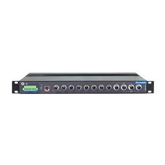
【Panel Design】
Front view
Model I
Model II
1.
Lugs
2.
Grounding screw
3.
Power P1 input terminal (P1)
4.
Relay alarm output terminal block
5.
Power P2 input terminal (P2)
6.
Power supply indicator (P1-P2)
7.
Running indicator (RUN)
8.
Alarm indicator (ALM)
9.
CONSOLE port
10.
Gigabit M12 interface (G1-G8)
11.
Gigabit Bypass M12 interface (Bypass: G9-G11,
G10-G12)
12.
Ethernet link indicator (1- 8, G1-G12)
13.
100M M12 Interface (1-8)
14.
Gigabit Bypass M12 interface (Bypass: G1-G3,
G2-G4)
【Mounting Dimension】
The shell dimension of this series of devices is the same, and
the dimension figure of model I is shown below. Unit: mm
Notice Before Mounting:
Don't place or install the device in area near water or
moist, keep the relative humidity of the device
surrounding between 5%~95% without condensation.
Before power on, first confirm the supported power
supply specification to avoid over-voltage damaging the
device.
The device surface temperature is high after running;
please don't directly contact to avoid scalding.
【Rack-mounted】
Step 1
Select the device mounting position and ensure
enough mounting size is reserved.
Step 2
Adopt bolts to install the mounting lugs in the
device position as figure below.
Step 3
Place the device on the rack surface plate; adopt 4
screws to mount the right and left mounting lugs on
the rack.
Advertisement

Subscribe to Our Youtube Channel
Related Manuals for 3onedata TNS5800 Series


Summary of Contents for 3onedata TNS5800 Series
- Page 1 Model I. TNS5800-12GT-X-2P110 (12 Gigabit M12, 110VDC dual power supply input) TNS5800 Series (12 Ports) Model II. TNS5800-8T4GT-2P110(8 100M M12 + 4 Gigabit M12, 110VDC dual power supply input) Layer 3 Rack-Mounted 【Panel Design】 Industrial Ethernet Switch Front view ...
- Page 2 alarm output, the relay occupies 2 pins, pin definition is shown Pin No. Definition Description as above. R1 and R2 are a group of normally open contacts of Positive bi-directional data of D0+ (DA+) the device alarm relay, which is open in normal no-alarm state Gigabit Ethernet group 1 and closed when any alarm information appears.
- Page 3 Indicate Description Packet buffer size 12Mbit the device. Blinking 1 time per second, MAC Address Table Blinking system is running normally Power supply Note: Ethernet interface Power input 110VDC(66~156VDC) The default IP address of the device is “192.168.1.254”. established valid network Dual power supply redundancy,...
Need help?
Do you have a question about the TNS5800 Series and is the answer not in the manual?
Questions and answers