Advertisement
Quick Links
TNS5500D Series
Managed Wall-mounted Industrial
Ethernet Switch Quick Installation
Guide
3onedata Co., Ltd.
Address:
3/B, Zone 1, Baiwangxin High Technology
Industrial
Park,
Xili,
Shenzhen
Website:
www.3onedata.com
Tel:
+86 0755-26702688
Fax:
+86 0755-26703485
【Package Checklist】
Please check whether the package and accessories are intact
while using the switch for the first time.
1.
Industrial Ethernet switch
3.
Quick installation guide
5.
Warranty card
If any of these items are damaged or lost, please contact our
company or dealers, we will solve it ASAP.
【Product Overview】
The series of product is 100M/Gigabit layer 2 managed
Wall-mounted industrial Ethernet switch designed for rail
transit industry. Modules as follows:
Model I
100M PoE copper ports)
Model II TNS5500D-4GT-8T (4 Gigabit copper ports + 8
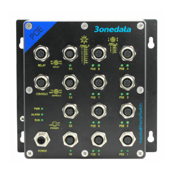
【Panel Design】
Front view
Nanshan
District,
2.
CD
4.
Certification
TNS5500D-4GT-8POE (4 Gigabit copper ports + 8
100M copper ports)
Model I
Model II
Bottom view
Top view
Left view
Advertisement

Related Manuals for 3onedata TNS5500D Series


Summary of Contents for 3onedata TNS5500D Series
- Page 1 Model I TNS5500D-4GT-8POE (4 Gigabit copper ports + 8 100M PoE copper ports) Model II TNS5500D-4GT-8T (4 Gigabit copper ports + 8 TNS5500D Series 100M copper ports) Managed Wall-mounted Industrial 【Panel Design】 Ethernet Switch Quick Installation Front view Guide Model II 3onedata Co., Ltd.
- Page 2 Right view 【Disassembling the Device】 Step 1 Device powers off Step 2 Unscrew the screws on the wall about 7mm. Step 3 Lift the device then take it out, disassembling ends. Attention before mounting: Note: Hanger Don't place or install the device in area near water or Power ON operation: first connect power line to the ...
- Page 3 【Relay Connection】 signal Negative Ethernet positive This device provides 1 M12 D-Coded 4-Pin slot 100M Ethernet received 【Checking LED Indicator】 (female) for relay output. R1 and R2 is a pair of signal positive This device provides LED indicators for monitoring the work normally open contacts of device alarm relay.
- Page 4 Step 2 Enter device’s IP address in the address bar of the 100M M12 10/100Base-T(X), M12 Protection grade IP30 (metal shell) computer browser. (Female), 4-Pin D-Coded, automatic flow control, full/half duplex mode, MDI/MDI-X automatic detection; Optional Step 3 Enter device’s username and password in the login PoE output.
Need help?
Do you have a question about the TNS5500D Series and is the answer not in the manual?
Questions and answers