Advertisement
TNS5800 Series
Layer 3 Rack-Mounted EN50155
Industrial Ethernet Switch
Quick Installation Guide
3onedata Co., Ltd.
Address:
3/B, Zone 1, Baiwangxin High Technology
Industrial Park, Song Bai Road, Nanshan
District, Shenzhen, 518108, China
Website:
www.3onedata.com
Tel:
+86 0755-26702688
Fax:
+86 0755-26703485
【Package Checklist】
Please check the integrity of package and accessories while
first using the switch.
1.
Switch ×1
2.
3.
Certificate
4.
If any of these items are damaged or lost, please contact our
company or dealers, we will solve it ASAP.
【Product Overview】
The products of this series are layer 3 EN50155 rack-mounted
industrial Ethernet switches. For convenience, the products of
this series adopt the following number on the left in this guide,
please confirm the number of your product:
Model I. TNS5800-8P4GT-2P110 (8 100M PoE M12 + 4
Model II. TNS5800-8GP4GT-2P110 (8 Gigabit PoE M12 + 4
Model III. TNS5800-16P4GT-2P110 (16 100M PoE M12 + 4
Model IV. TNS5800-16P4GT-2P24 (16 100M PoE M12 + 4
Model V. TNS5800-16GP4GT-2P110 (16 Gigabit PoE M12 + 4
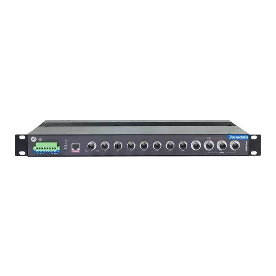
【Panel Design】
Front view
1.
2.
3.
4.
5.
6.
7.
8.
9.
Lugs
10.
Warranty card
11.
12.
13.
14.
15.
16.
Gigabit M12, 110VDC dual power supply input)
Gigabit M12, 110VDC dual power supply input)
Gigabit M12, 110VDC dual power supply input)
Gigabit M12, 24VDC dual power supply input)
Gigabit M12, 110VDC dual power supply input)
Model I
Model II
Lugs
Grounding screw
Power P1 input terminal (P1)
Relay alarm output terminal block
Terminal block for power P2 input (P2)
Power supply indicator (P1-P2)
Running indicator (RUN)
Alarm indicator (ALM)
CONSOLE port
100M PoE M12 interface (1--8)
PoE indicator (1--8)
Gigabit Bypass M12 interface (Bypass: G1-G3,
G2-G4)
Ethernet port indicator (1-8, G1-G4)
Gigabit PoE M12 interface (G1-G8)
PoE indicator (G1-G8)
Gigabit Bypass M12 interface (Bypass: G9-G11,
G10-G12)
17.
Ethernet port indicator (G1-G12)
Model III, Model IV
Model V
1.
Lugs
2.
Power supply input and relay output interface
3.
PoE indicator (E1-E16)
4.
Grounding screw
5.
Ethernet port indicator (E1-E16, G1-G4)
6.
100M PoE M12 interface (E1-E16)
7.
Gigabit Bypass M12 interface (Bypass: G1-G2,
G3-G4)
8.
Power supply indicator (P1-P2)
9.
RESET button
10.
CONSOLE port
11.
Running indicator (RUN)
12.
Alarm indicator (ALM)
13.
PoE indicator (G1-G16)
14.
Ethernet port indicator (G1-G20)
15.
Gigabit PoE M12 interface (G1-G16)
16.
Gigabit Bypass M12 interface (Bypass: G17-G18,
G19-G20)
【Mounting Dimension】
Unit: mm
Model I and Model II
Advertisement
Table of Contents

Related Manuals for 3onedata TNS5800 Series


Summary of Contents for 3onedata TNS5800 Series
- Page 1 Gigabit M12, 110VDC dual power supply input) Model II. TNS5800-8GP4GT-2P110 (8 Gigabit PoE M12 + 4 Gigabit M12, 110VDC dual power supply input) TNS5800 Series Model III. TNS5800-16P4GT-2P110 (16 100M PoE M12 + 4 Layer 3 Rack-Mounted EN50155 Model III, Model IV...
-
Page 2: Power Supply Connection
【Disassembling Device】 Power off the device. Notice Before Mounting: Unscrew the fixed mounting lug screw on the rack. Don't place or install the device in area near water or moisture, keep the relative humidity of the device Shift out the device from rack, disassembling ends. surrounding between 5%~95% without condensation. -
Page 3: Communication Interface Connection
terminal blocks and support 1 relay alarm output, the relay Pin No. Definition Pin Description Pin No. Definition Description occupies 2 pins, pin definition is shown in the above figure. R1 Positive send data of 100M Gigabit Ethernet group 4 and R2 are a group of normally open contacts of the device Ethernet D3- (DD-) -
Page 4: Specification
【Logging in to WEB Interface】 settings, so please backup configuration file in advance. Alarm port 8-pin 5.08mm pitch terminal Support WEB management and configuration. Computer can Please refer to user manual for specific configuration blocks (relay occupies 2 pins) or ... - Page 5 Professional users should contact their suppliers and check Model IV Power input: 24VDC(18~36VDC), dual the terms of their selling agreement. power supply redundancy, This product must not be disposed of with other commercial support anti-reverse waste. connection protection Users’ cooperation in the correct disposal of this product will Connection method: 7-PIN ...
Need help?
Do you have a question about the TNS5800 Series and is the answer not in the manual?
Questions and answers