Inspired Flight IF1200 User Manual
Herelink blue, herelink black, lrt
Hide thumbs
Also See for IF1200:
- User manual (73 pages) ,
- User manual (35 pages) ,
- Setup manual (12 pages)

Related Manuals for Inspired Flight IF1200


Summary of Contents for Inspired Flight IF1200
- Page 1 IF1200 Hexacopter HereLink Blue HereLink Black User Manual IFT Doc. Num. 102090, Rev. 3.00...
- Page 2 Inspired Flight Technologies. The information, technical data, designs and drawings disclosed in this document are proprietary information of Inspired Flight Technologies or third parties and shall not be used or disclosed to any third party without permission of Inspired Flight Technologies.
-
Page 3: Table Of Contents
IF1200 User Manual Table of Contents Safety Information and Notes IF1200 Overview Hand Controllers HereLink Blue Hand Controller HereLink Black Hand Controller Long Range Telemetry (LRT) Battery Charging Install QGroundControl Assemble the Aircraft Using HereLink Hand Controllers Set Up the Long Range Telemetry (LRT) Radio... -
Page 4: Safety Information And Notes
1. Safety Information and Notes 1. Safety Information and Notes The IF1200 is a high-performance system, engineered for safe use. Where appropriate, this manual alerts the user to specific actions necessary for safe operation of the aircraft. The following symbols are used:... -
Page 5: If1200 Overview
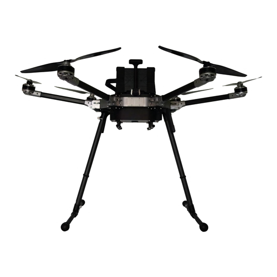
Figure 1 below shows major components of the IF1200 aircraft. Figure 2 on the next page shows the front view of the aircraft, Orientation: In this manual, the side of the IF1200 that has the GPS mast is referred to as the “front” of the aircraft. - Page 6 IF1200 User Manual 2. IF1200 Overview Figure 2. Front View of the IF1200 Aircraft IFT Doc. Num. 102090, Rev. 3.00 Page 3...
-
Page 7: Hand Controllers
3. Hand Controllers 3. Hand Controllers The IF1200 includes one of the hand controllers shown below. Click on the link to go to the page for that hand controller. NOTE: The HereLink Blue and HereLink Black both have QGroundControl software installed at the factory. -
Page 8: Herelink Blue Hand Controller
IF1200 User Manual 4. HereLink Blue Hand Controller 4. HereLink Blue Hand Controller This configuration uses the HereLink Blue hand controller, made by Union Robotics. The User Guide for this hand controller can be found online at: https://docs.union-robotics.com/manuals/blue-herelink-overview The HereLink Blue GCS has an internal battery which can be charged via a micro USB port on the bottom of the unit. -
Page 9: Herelink Black Hand Controller
IF1200 User Manual 5. HereLink Black Hand Controller 5. HereLink Black Hand Controller This IF1200 version uses the HereLink Black hand controller, made by CubePilot. The HereLink Black User Guide can be found online at: https://www.cubepilot.com/#/herelink/features Note: The HereLink hand controller can be used while it is being charged. -
Page 10: Long Range Telemetry (Lrt)
IF1200 User Manual 6. Long Range Telemetry (LRT) 6. Long Range Telemetry (LRT) Description The LRT kit includes: ● IF1200 aircraft ● Jeti DS-12 hand controller ● RFD900x-US telemetry radio Customer-supplied: ● Laptop or tablet, with QGroundControl installed. The RFD900x-US telemetry radio plugs into a USB port on this device. - Page 11 IF1200 User Manual 6. Long Range Telemetry (LRT) Figure 6. Jeti DS-12 Hand Control IFT Doc. Num. 102090, Rev. 3.00 Page 8...
-
Page 12: Battery Charging
7. Battery Charging 7. Battery Charging The IF1200 kit uses a Tattu TA1200 battery charger (see below) for charging the flight batteries. The Tattu charger can charge two batteries simultaneously. Looking at the top of the charger, you can see that both sides of the charger have the same controls, outputs, and displays. - Page 13 IMPORTANT! Read the accompanying charger manual thoroughly before connecting power and batteries to the charger. It contains important safety information. Balancing cells: The flight batteries used in the IF1200 contain multiple cells. Differences in the voltages between cells can degrade the performance of the NOTE batteries, and shorten its life.
- Page 14 IF1200 User Manual 7. Battery Charging Charge the Flight Batteries, Continued Step Action Rotate the Charge Mode dial (see below) to select the charge mode. There are three charging modes: ● Trickle: The slowest charging rate. Use Trickle mode when possible to extend the battery life.
- Page 15 IF1200 User Manual 7. Battery Charging Charge the Flight Battery, Continued Step Action Uncap the battery cable and plug it into the Power Interface port on the charger (see below). Note: The battery cable and Power Interface port on the charger are designed to prevent incorrect mating of the two.
- Page 16 7. Battery Charging Balancing the Battery’s Cells The flight battery used with the IF1200 are composed of individual cells. During the life of a battery, individual cells voltages may differ from each other, which shortens the lifespan of the battery. The cells’ voltages must be ‘balanced’ so that all of the cells’ voltages are within the same voltage range.
- Page 17 IF1200 User Manual 7. Battery Charging Troubleshooting Battery Charging Error message appears on the screen: ● Unplug the battery and press the ‘Charge’ button to reset the interface. Popping or arcing when plugging the battery into the charger: ● The battery likely needs to be balanced. Plug in the balance cable to both the charger and battery, then plug the main lead of the battery into the charger to conduct a balance charge.
-
Page 18: Install Qgroundcontrol
IF1200 User Manual 8. Install QGroundControl 8. Install QGroundControl QGroundControl (QGC) is an open-source mission planning and configuration software for aircraft using the MAVLink Communication Protocol. QGC is extremely well documented and we encourage all first-time users to review the available user guide at: https://docs.qgroundcontrol.com/en/. -
Page 19: Assemble The Aircraft
Insert the vertical tube so that the notch aligns with the inner features of the horizontal tube, so that the vertical tube is fully seated in the horizontal tube. Continued next page Figure 8. IF1200 Landing Gear Assembly IFT Doc. Num. 102090, Rev. 3.00 Page 16... - Page 20 IF1200 User Manual 9. Assemble the Aircraft Step Action The ratcheting arm can be pulled away from the screw to move the arm to a more convenient location when tightening. Tighten the clamp. Repeat steps 3 through 5 to assemble the second landing gear.
- Page 21 IF1200 User Manual 9. Assemble the Aircraft Step Action Lift the GPS mast into the upright position, latching the clips on both sides of the mast (see below). Continued next page Figure 10. Lock the GPS Mast in Place IFT Doc. Num. 102090, Rev. 3.00...
- Page 22 IF1200 User Manual 9. Assemble the Aircraft Step Action Unfold the two aircraft arms that are over the landing gear sockets into their extended position. The arms will lock securely into place (see below). Continued next page Figure 11. Lock the Arms into Place IFT Doc.
- Page 23 IF1200 User Manual 9. Assemble the Aircraft Step Action Insert the landing gear legs into the corresponding sockets on the underside of the aircraft. Ensure the notch at the end of the tube is aligned with the corresponding key inside the socket.
- Page 24 IF1200 User Manual 9. Assemble the Aircraft Install the Flight Battery in the Aircraft Step Action Ensure the velcro straps on top of the aircraft are unfastened and moved out of the way so that the battery can be placed on top of the aircraft.
- Page 25 IF1200 User Manual 9. Assemble the Aircraft Install the Flight Battery in the Aircraft, Continued Step Action Locate the battery straps and loop the ends through the metal loops on the opposite side. Pull the straps tightly over the battery.
- Page 26 IF1200 User Manual 9. Assemble the Aircraft Install the Flight Battery in the Aircraft, Continued Step Action Secure the velcro strap tightly to itself close to the body of the aircraft. Plug in the male battery connector on the battery cable into the female battery connector on the aircraft (see below).
-
Page 27: Using Herelink Hand Controllers
IF1200 User Manual 10. Using HereLink Hand Controllers 10. Using HereLink Hand Controllers Both the HereLink Blue and HereLink Black hand controllers have QGroundControl (QGC) software installed at the factory. QGC is extremely well documented and we encourage all first-time users to review the available user guide at: https://docs.qgroundcontrol.com/en/. - Page 28 IF1200 User Manual 10. Using HereLink Hand Controllers Step Action GPS satellite count and status: This is indicated in the toolbar at the top of the QGroundControl screen (see below). The top number is the satellite count, the bottom number is the HDOP (horizontal dilution of precision).
-
Page 29: Set Up The Long Range Telemetry (Lrt) Radio
11. Set up the Long Range Telemetry Radio 11. Set Up the Long Range Telemetry (LRT) Radio Note: The IF1200 LRT can be flown in Position or Return to Launch modes using only the Jeti DS-12 transmitter. For Altitude mode and autonomous missions that require location information (GNSS) and aircraft information, a ground station (laptop or tablet) with the RFD900x-US connected to it and QGC installed is required. - Page 30 IF1200 User Manual 11. Set up the Long Range Telemetry Radio Step Action Turn on the Jeti DS-12 by pressing the Power button for two seconds (see below). When the screen activates, it prompts you with, “Start Transmitter?” Press the button “Yes”...
-
Page 31: Power On The Aircraft
IF1200 User Manual 12. Power On the Aircraft 12. Power On the Aircraft Step Action Press and hold the power button on the chassis at the rear of the aircraft (see below) until the button illuminates green. The LED indicators turn on after about 7 seconds. -
Page 32: Flight Modes
Position mode to regain control. Moving a joystick during an autonomous mission reverts control back to the pilot. The IF1200 automatically returns to the launch site as a failsafe when the battery voltage gets too low to continue flight; visually monitor the battery level in QGC and replace the battery conservatively to mitigate risk. - Page 33 IF1200 User Manual 13. Flight Modes Selecting Flight Modes on the Hand Controllers This section describes the location and function of the flight mode controls on the hand controllers. See Figure 12 and Figure 13 below for control locations. Flight Mode Controls...
- Page 34 IF1200 User Manual 13. Flight Modes Jet DS-12: When the Mode Switch on the Jeti DS-12 is used to switch flight modes, the QGroundControl display on the ground control station updates to show the new flight mode. HereLink: The current flight mode is indicated in the top right corner of the QGC display (see Figure 14 below).
-
Page 35: Arm And Disarm
IF1200 User Manual 14. Arm and Disarm 14. Arm and Disarm ● Arm means to start the propellers spinning. ● Disarm means to stop the propellers from spinning. Step Action Arming Verify each item on the Preflight Checklist (see the end of this User Manual). -
Page 36: Takeoff And Landing
IF1200 User Manual 15. Takeoff and Landing 15. Takeoff and Landing Step Action Takeoff Verify each item on the Preflight Checklist (see the end of this User Manual). Takeoff by slowly raising the throttle (left joystick). The throttle must be raised above the midpoint. -
Page 37: Power Off The Aircraft
Action Power down any Sony camera attached to the aircraft. Press the power button on the IF1200 (see below) to power off the aircraft Disconnect the battery (pull on the connector, not the wires). Power down the hand controller by holding the Power button in, then follow the on-screen prompts. -
Page 38: Planning A Mission
IF1200 User Manual 17. Planning a Mission 17. Planning a Mission This section presents the basics of setting up an autonomous mission in QGC and then describes in detail how to create an example mission. Once you are comfortable flying the aircraft, learning how to plan an autonomous mission greatly expands the applications of the aircraft. - Page 39 IF1200 User Manual 17. Planning a Mission QGroundControl User Interface Overview The main elements of the User Interface (UI) for planning a mission are described below (see Figure 17 on the previous page) ● Map (main area of display): Displays the numbered indicators for the current mission, including the Planned Home.
- Page 40 IF1200 User Manual 17. Planning a Mission Example Mission The basic steps for planning and executing a mission are: 1. In QGroundControl, change to Plan view. 2. Set Home position 3. Add waypoints 4. Set landing point 5. Upload the mission to the aircraft.
- Page 41 IF1200 User Manual 17. Planning a Mission Example Mission, Continued Step Action On the left side of the screen, locate the Create Plan overlay. Select (mouse click or tap screen) Blank. Note: Other Plan types are available. The Blank plan is chosen for illustration purposes for this example.
- Page 42 IF1200 User Manual 17. Planning a Mission Step Action On the Plan Tools panel on the left side of the screen, select the Takeoff button (#1 below). The Takeoff icon appears (# 2 in the screenshot below). Note: A Takeoff panel appears in the Mission Command List on the right side of the screen when the Takeoff icon is selected.
- Page 43 IF1200 User Manual 17. Planning a Mission Step Action Place the first Waypoint: 1. In the Plan Tools, select Waypoint (#1 below). 2. Place the cursor on the map for the desired Waypoint location (#2 below), then select it 3. Notice that the Waypoint panel appears on the right side of the screen when Waypoint was selected in the Plan Tools panel.
- Page 44 IF1200 User Manual 17. Planning a Mission Step Action After you’ve added the desired Waypoints, complete the mission plan by creating a Return to Launch point. In the Plan Tools panel, select the Return icon (#1 below). When you select Return, the default is Return to Launch (RTL), as shown in the Mission Command List.
- Page 45 IF1200 User Manual 17. Planning a Mission Step Action The Basic Mission Command Editor (the left image in the figure below) offers Return and other options. Note: If you select the down arrow next to the Basic category (see the figure below), it opens a dropdown menu (right side of the figure), that offers more Mission Command Editors.
- Page 46 IF1200 User Manual 17. Planning a Mission Example Mission, Continued Step Action After you have finished planning a mission, you can see details of the mission in the Mission Command List, on the right side of the screen. To see details about individual events in the mission, select an event, such as a Waypoint, and details about that event appear below it (see the figure below).
- Page 47 IF1200 User Manual 17. Planning a Mission Example Mission, Continued Step Action Select the Fly icon at the top of the Tools panel (see below). A Start Mission window appears at the bottom of the QGC screen (see Figure 24 below).
-
Page 48: Preflight Checklist
IF1200 User Manual Preflight Checklist Preflight Checklist All six arms are lifted and latched in position. The GPS mast is lifted and latched on both sides. Check that the propellers rotate freely. The antenna(s) is (are) plugged into the top of the hand controller or telemetry radio. -
Page 49: Appendix
IF1200 User Manual Appendix Appendix This Appendix addresses the topics listed below. Click on a topic to go to that page. Security Risks and Mitigation Registering an Aircraft with the FAA Critical Situations Upgrading the Aircraft Firmware Calibrate the Compass... -
Page 50: Security Risks And Mitigation
● Missions can also be deleted during flight, while the aircraft is connected to the ground station. Issue: Data Encryption ● Enable AES Encryption and change the Encryption keys often. Refer to the following document, available from Inspired Flight Technologies: ● Long Range Telemetry Modem Configuration Supplement IFT Doc. Num. 102090, Rev. 3.00 Page 47... -
Page 51: Registering An Aircraft With The Faa
IF1200 User Manual Appendix Registering an Aircraft with the FAA U.S. law requires that all unmanned aerial aircrafts must be registered with the FAA prior to flight. Go to this link to register the aircraft: https://faadronezone.faa.gov/ We recommend that you print the FAA registration number and affix it to the aircraft, on the top carbon plate where the battery is mounted. -
Page 52: Critical Situations
Total Loss of aircraft ● : If a flyaway or battery depletion away from the home point occurs, follow the FAA guidelines on aircraft loss, and contact Inspired Flight for further instruction. Aircraft Crash ●... -
Page 53: Upgrading The Aircraft Firmware
IF1200 User Manual Appendix Upgrading the Aircraft Firmware Note: Firmware upgrades are only necessary if advised by Inspired Flight. The aircraft comes with firmware installed at the factory. Step Action Completely power off the aircraft. Open QGroundControl on a PC. - Page 54 IF1200 User Manual Appendix Upgrading the Aircraft Firmware, Continued Step Action On the right side of the PC’s screen, a ‘Firmware Setup’ window will appear. Select the ‘Advanced Settings’ checkbox (see below). Under the dropdown menu, select ‘Custom firmware file’ (see below). Select ‘OK.’...
- Page 55 IF1200 User Manual Appendix Upgrading the Aircraft Firmware, Continued Step Action Navigate to the correct firmware file, and select ‘Open’. Wait about one minute for the firmware to upgrade. The beeping will stop when the upgrade is complete. Below is a screenshot of the firmware upload progress.
-
Page 56: Calibrate The Compass
IF1200 User Manual Appendix Calibrate the Compass This section describes how to calibrate the internal compass in the aircraft. The aircraft’s compass is calibrated at the factory and typically does not need to be re-calibrated. Compass calibration may be necessary if significant hardware changes NOTE have been made or if metal has been added to or removed from the aircraft. - Page 57 IF1200 User Manual Appendix Calibrate the Compass, Continued Step Action In QGC, select the Gear icon (Vehicle Setup) in the top toolbar, and then Sensors in the left sidebar (see below). Click the Compass button. Click OK to start the calibration.
- Page 58 IF1200 User Manual Appendix Calibrate the Compass, Continued Step Action The steps that follow are excerpted from the PX4 User Guide, and show a fixed-wing NOTE aircraft. The orientations apply to a rotary wing aircraft as well. The display shown below appears. Orientations shown in red are “incomplete,” and must be calibrated.
-
Page 59: Calibrate The Accelerometers
Appendix Calibrate the Accelerometers This section describes how to calibrate the accelerometers on the aircraft. Accelerometer calibration is not normally required unless instructed by Inspired Flight Customer Support. For more information about this procedure, click the following link: https://docs.px4.io/v1.9.0/en/config/accelerometer.html Step Action Start QGroundControl and connect it to the aircraft. - Page 60 IF1200 User Manual Appendix Calibrate the Accelerometers, Continued Step Action Click OK to start the calibration. Position the aircraft as shown by the images on the screen (see figure below). An orientation image’s border will turn yellow, prompting you to hold the aircraft still in the orientation shown.
-
Page 61: If1200 Maintenance Schedule
IF1200 User Manual Appendix IF1200 Maintenance Schedule Maintenance Intervals (Every X Flights) Recommended Every 1 1600 Maintenance Activities Flight Flights Flights Flights Flights Flights Flights Flights Inspect all moving components for wear/damage. Check propellers for damage. Dust all lenses Inspect all visible screws &... -
Page 62: Revisions
IF1200 User Manual Appendix Revisions Revision Changes Date Number approved ● New format 3.00 ● Added section in Appendix on Security Risks and Mitigation IFT Doc. Num. 102090, Rev. 3.00 Page 59...
Need help?
Do you have a question about the IF1200 and is the answer not in the manual?
Questions and answers