Inspired Flight IF1200 User Manual
Hide thumbs
Also See for IF1200:
- User manual (73 pages) ,
- Setup manual (12 pages) ,
- User manual (62 pages)
Table of Contents
Advertisement
Quick Links
Advertisement
Table of Contents

Related Manuals for Inspired Flight IF1200


Summary of Contents for Inspired Flight IF1200
- Page 1 IF1200 Hexacopter User Manual ...
-
Page 2: Table Of Contents
Table of Contents Aircraft Overview 3 Controller Overview 4 Tattu TA1200 Battery Charger 6 Battery C harging Instructions 7 Installing QGroundControl 10 Set-Up Aircraft 11 Installing Batteries 14 Installing Propellers 17 Powering On Vehicle 20 Powering On Controller 21 ... -
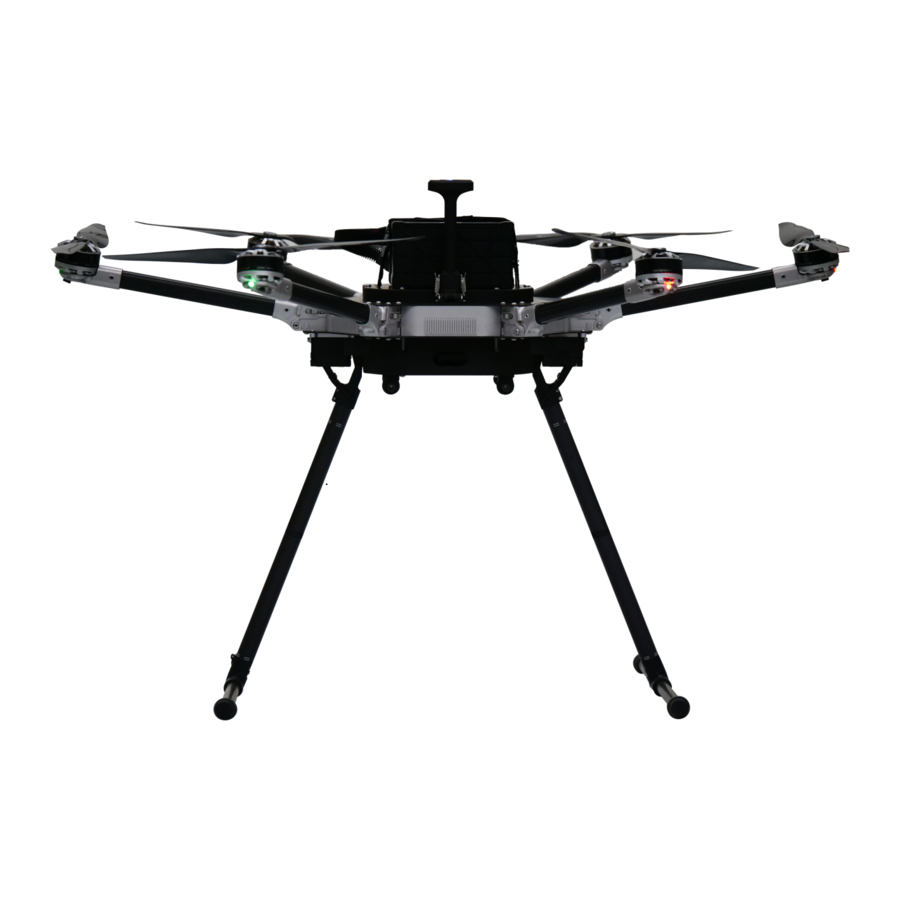
Page 3: Aircraft Overview
1. Product Profile 1.1. Aircraft Overview Each IF1200 comes bound and ready to fly. Listed below are all the various subassemblies included in the kit. 3 ... -
Page 4: Controller Overview
1.2. Controller Overview Jeti DS-12 Controller Note: Switches not labelled are not programmed for standard use, but can be customized to conduct any Mavlink commands 4 ... - Page 5 Herelink Controller Note: Switches labeled as ‘Disabled’ are not programmed for standard use, but can be customized to conduct any Mavlink commands 5 ...
-
Page 6: Tattu Ta1200 Battery Charger
2. Flight Instructions 2.1. Tattu TA1200 Battery Charger 6 ... -
Page 7: Battery Charging Instructions
Battery Charging Instructions Plug in the charger unit using the power cable included. Make sure the charger is plugged into a 110v power source. Press the power button on the side of the battery charger to power on the unit. Fans will begin spinning, and the LCD screen on each side of the charger will ... - Page 8 Adjust the charge mode dial. There are three charge mode options: Trickle, Standard, and Fast. If time is not an issue, it is recommended to charge the batteries as slowly as possible for extended battery health. Uncap the battery and plug into one side of the charger. ...
- Page 9 Once connected, the battery will go through a precharge countdown of 10 seconds, then will begin charging automatically. To skip the precharge countdown, hold the ‘Charge’ button for 2 seconds. Cell voltages and battery levels will be indicated on the LCD screen. Balancing Instructions ...
-
Page 10: Installing Qgroundcontrol
, then install QGC on your PC or USB-C enabled Tablet. The Inspired Flight UAV will automatically connect to QGC once the vehicle has been powered on and the USB telemetry module (included) has been plugged into the PC or Tablet. ... -
Page 11: Set-Up Aircraft
2.3. Set-Up Aircraft Locate the two parts that make up each side of the landing gear. Loosen the clamp on the horizontal tube (with rubber feet), then assemble the landing gear by inserting the vertical tube fully into the horizontal tube. The notches on the end inserts should line up perpendicularly to the horizontal tube. ... - Page 12 Remove the body of the drone from the case. Note: T he next steps are most easily done with two people (one person holding body, one assembling). Lift the GPS mast into place, latching the clips on both sides. ...
- Page 13 Locate the assembled landing gear. Insert the landing gear legs into the corresponding sockets on the underside of the vehicle. Again, ensure the vertical tube is fully seated before tightening the ratcheting clamp. The ratcheting arm can be pulled away from the screw to move the arm to a more convenient location when tightening. ...
-
Page 14: Installing Batteries
2.4. Installing Batteries Ensure the velcro straps on top of the vehicle are unfastened and moved away from the top plate’s center. Lay the battery on the foam pad at the top of the vehicle, ensuring: The battery is oriented such that the battery’s indicator lights and cables are at the rear of the vehicle. ... - Page 15 Locate the battery straps and loop the ends through themselves over the body of the battery. The plastic loop should be close to the center of the battery. Pull the straps tightly over the battery, securing the velcro strap to itself close to the body of the vehicle.
- Page 16 Plug in the male battery connector on the battery into the female battery connector on the aircraft. N ote: T he connector design ensures a mistake can not be made with the connector orientation. Ensure the connectors are pushed together fully. ...
-
Page 17: Installing Propellers
2.5. Installing Propellers Locate the correct prop for each motor. As seen in the photo below, three of the IF1200’s motors will spin clockwise, and three will spin counterclockwise. The two motor and prop types have keyed quick-disconnects that prevent a user from mounting the wrong ... - Page 18 Ensuring the screws line up with the corresponding screw holes on the motor, place each propeller on its motor. Make sure each propeller is fully seated, with the aluminum quick-disconnect resting on the motor itself. Tighten the propellers onto the motors, ensuring not to over-tighten. We recommend using the provided green-handled screwdriver.
- Page 19 When the propellers are mounted correctly, the propellers should be parallel to the top surface of the motor, and everything should be fully seated and firmly secured. ...
-
Page 20: Powering On Vehicle
2.6. Powering On Vehicle To power the IF1200, press and hold the power button on the rear of the vehicle for 5 seconds. The LED indicator light will turn green when the aircraft is on, and beeping will occur during the initialization sequence. The LED on the GPS mast will begin breathing ... -
Page 21: Powering On Controller
2.8. Flight Modes There are a few flight modes on the IF1200, discussed below. They provide the ability to switch between partial manual flight and autonomous flight/landing. Altitude Mode In Altitude mode, the IF1200 will maintain its vertical position with the left stick ... -
Page 22: Return To Home Mode
When return mode is activated, the IF1200 will automatically return to its home position. The home position is set by the location where the IF1200 is armed. If the drone is below an altitude of 30 meters, it will first rise to 30 meters before ... -
Page 23: Opening Qgroundcontrol
2. Vehicle setup Configure and adjust tuning for the UAV. Adjusting these settings are not recommended without consulting Inspired Flight and may cause any warranty to be voided. All vehicles are tuned for optimal performance 23 ... - Page 24 prior to customer delivery. 3. Plan This screen is used to plan and upload autonomous missions to the UAV. Individual waypoints can be added and configured to plan a mission. There are automatic tools to create various patterns such as surveys and corridor scans. A mission command list will be on the right hand of the screen and will provide the ...
-
Page 25: Arming And Takeoff
I f the drone begins to tip over on takeoff, immediately lower the throttle and disarm. If this occurs, it is likely that a propeller was installed on a wrong motor, or an ESC is not calibrated properly. Contact Inspired Flight for diagnostic instructions. ... -
Page 26: Landing And Disarming
To land the aircraft (in position mode), simply lower the throttle completely until the drone has landed. Be sure the landing site is level and clear of obstructions. The IF1200 utilizes a Lidar Lite sensor and will slow itself down before landing. ... -
Page 27: Planning An Autonomous Mission
2.12. Planning an Autonomous Mission Once the pilot is comfortable with flying the aircraft, planning an autonomous mission is a very useful feature to learn. The following information and images have been gathered from QGroundControl’s site, which can be referenced for any additional questions. ... - Page 28 Note: Max telem dist is the distance between the Planned Home and the furthest waypoint. Upload Button: When planning is complete, use this button to upload the plan to the vehicle. Plan Tools: Used to create and manage missions. ...
- Page 29 The Fly View displays the actual home position set by the vehicle firmware when it arms (this where the vehicle will return in Return/RTL mode). Plan Tools The plan tools are used for adding individual waypoints, easing mission creation for complicated geometries, uploading/downloading/saving/restoring missions, ...
- Page 30 and rally points. Within the list you can select individual mission items to edit their values. Mission Settings The ‘Mission Start’ panel is the first item that appears in the mission command list. It may be used to specify a number default settings that may affect the start or end of the mission. ...
- Page 31 This is only the planned home position and you should place it where you plan to start the vehicle from. It has no actual impact on flying the mission. The actual home position of the IF1200 is set by the vehicle itself when arming. ...
-
Page 32: Motor Navigation Lights
If you are planning a mission while you are connected to a vehicle the firmware and vehicle type will be determined from the vehicle. This section allows you to specify the vehicle firmware/type when not connected to the IF1200. ... -
Page 33: Appendix
3. Appendix 3.1. Registering Vehicle with FAA According to national law, all unmanned aerial vehicles must be registered with the FAA prior to flight. Register the aircraft here: ttps://faadronezone.faa.gov/ It is recommended that the FAA registration number be printed and stuck to the top carbon plate where the battery is mounted. ... - Page 34 Click the ‘Compass’ tab, and ensure orientation is set to ‘ROTATION_NONE’. After hitting ‘OK’, the drone must be rotated about a vertical axis (the human body) for seven seconds in each of the orientations shown. Green boxes show complete orientations, the yellow box shows current calibrating orientation, and red boxes indicate incomplete orientations. ...
-
Page 35: Re-Binding The Controller
Entire Loss of Vehicle: I f a flyaway or battery depletion away from the home point occurs, follow the FAA guidelines on vehicle loss, and contact Inspired Flight for further instruction. Vehicle Crash: I f the aircraft is flown into an obstruction or crashes for any reason, follow ...
Need help?
Do you have a question about the IF1200 and is the answer not in the manual?
Questions and answers