
Related Manuals for Inspired Flight IF1200A


Summary of Contents for Inspired Flight IF1200A
- Page 1 IF1200A Hexacopter HereLink Blue HereLink Black Long Range Telemetry Pilot Operating Handbook IFT Doc. Num. 102094, Rev. 1.02, 2022...
- Page 2 Inspired Flight Technologies. The information, technical data, designs and drawings disclosed in this document are proprietary information of Inspired Flight Technologies or third parties and shall not be used or disclosed to any third party without permission of Inspired Flight Technologies.
-
Page 3: Table Of Contents
IF1200A Pilot Operating Handbook Table of Contents 1. Safety Information and Notes 2. IF1200A Overview 3. Hand Controller Descriptions 4. HereLink Blue Hand Controller 5. HereLink Black Hand Controller 6. Long Range Telemetry (LRT) 9. Battery Charging 10. Assemble the Aircraft 11. -
Page 4: Safety Information And Notes
1. Safety Information and Notes 1. Safety Information and Notes The IF1200A is a high-performance system, engineered for safe use. Where appropriate, this manual alerts the user to specific actions necessary for safe operation of the aircraft. The following alert symbols are used:... -
Page 5: If1200A Overview
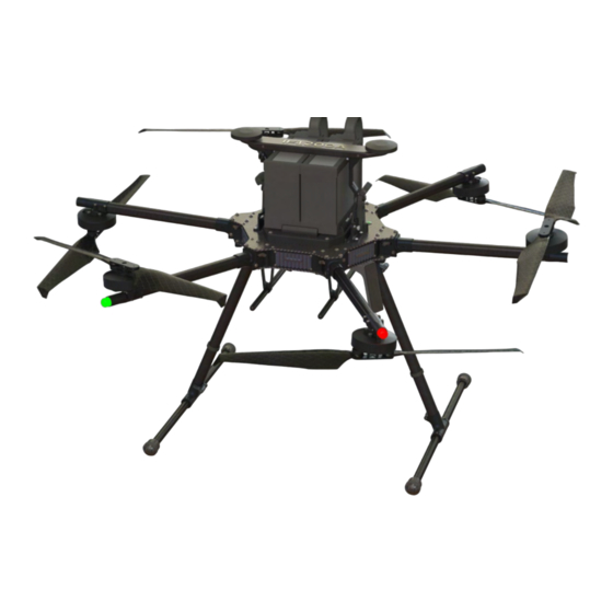
All three versions of the IF1200A are identical except for the remote control. This Pilot Operating Handbook (POH) describes all three versions. Figure 1 below is a front view of the IF1200A aircraft. See Figure 2 on the following page for a top view. - Page 6 IF1200A Pilot Operating Handbook 2. IF1200A Overview Figure 2 below is a top view of the IF1200A aircraft, and shows some features used to orient yourself to the aircraft. NOTE: The Handle incorporates a dual GPS, and also serves as a battery clamp for the aircraft.
-
Page 7: Hand Controller Descriptions
3. Hand Controller Descriptions 3. Hand Controller Descriptions The IF1200A includes one of the hand controllers shown below. Click on the link to go to the page for that hand controller. NOTE: The HereLink Blue and HereLink Black both have QGroundControl software installed. -
Page 8: Herelink Blue Hand Controller
IF1200A Pilot Operating Handbook 4. HereLink Blue Hand Controller 4. HereLink Blue Hand Controller This configuration uses the HereLink Blue hand controller, made by NW Blue. The User Guide for this hand controller can be found online at: https://docs.nwblue.com/nw-blue/products/herelink-blue The HereLink Blue has an internal battery which can be charged via a micro USB port on the bottom of the unit. -
Page 9: Herelink Black Hand Controller
IF1200A Pilot Operating Handbook 5. HereLink Black Hand Controller 5. HereLink Black Hand Controller This IF1200A version uses the HereLink Black, made by CubePilot. The HereLink Black User Guide can be found online at: https://docs.cubepilot.org/user-guides/herelink/herelink-overview The HereLink Black has an internal battery which can be charged via a micro USB port on the bottom of the unit. -
Page 10: Long Range Telemetry (Lrt)
IF1200A Pilot Operating Handbook 6. Long Range Telemetry (LRT) 6. Long Range Telemetry (LRT) The LRT system includes: ● IF1200A aircraft ● Jeti DS-12 hand controller ● RFD900x-US telemetry radio Customer-supplied: ● Laptop or tablet, with QGroundControl and/or Mission Planner installed. The RFD900x-US telemetry radio plugs into a USB port on this device. - Page 11 IF1200A Pilot Operating Handbook 6. Long Range Telemetry (LRT) Figure 6 below shows the Jeti DS-12 remote control. Figure 6. Jeti DS-12 Hand Control Flight Mode Switch Settings on Jeti DS-12 The Flight Mode Switch in the upper-right corner of the Jeti DS-12 (see Figure 6 above) is a...
- Page 12 IF1200A Pilot Operating Handbook 7. Install QGroundControl Install QGroundControl QGroundControl (QGC) is an open-source mission planning and configuration software application for UAVs using the MAVLink Communication Protocol. QGC is well documented, and first-time users are encouraged to review the available user guide at: https://docs.qgroundcontrol.com/en/.
- Page 13 IF1200A Pilot Operating Handbook 8. Install Mission Planner Install Mission Planner Mission Planner is an open-source mission planning and configuration software application for UAVs using the MAVLink Communication Protocol. Mission Planner is well documented, and first-time users are encouraged to review the available user guide at: https://ardupilot.org/planner/.
-
Page 14: Battery Charging
9. Battery Charging 9. Battery Charging The IF1200A kit includes a Tattu TA1200 battery charger (see below) for charging the flight batteries. The Tattu charger can charge two batteries simultaneously. Looking at the top of the charger, you can see that both sides of the charger have the same controls, outputs, and displays. - Page 15 IMPORTANT! Read the accompanying charger manual thoroughly before connecting power and batteries to the charger. It contains important safety information. Balancing cells: The flight batteries used in the IF1200A contain multiple cells. Differences in the voltages between cells can degrade the performance of the NOTE batteries, and shorten its life.
- Page 16 IF1200A Pilot Operating Handbook 9. Battery Charging Charge the Flight Batteries, Continued Step Action Rotate the Charge Mode dial (see below) to select the charge mode. There are three charging modes: ● Trickle: The slowest charging rate. Use Trickle mode when possible to extend the battery life.
- Page 17 Note: The battery cable and Power Interface port on the charger are designed to prevent incorrect mating of the two. Locate the Balance Cable in the aircraft kit (see Figure 8, below). NOTE: The balance cable for the IF1200A is different from the balance cable for IF1200. Figure 8. Balance Cable IFT Doc Num 102094, Rev 1.02...
- Page 18 IF1200A Pilot Operating Handbook 9. Battery Charging Step Action Connect one end of the Balance Cable to the Balance Interface on the charger (see Figure 7), and the other end to the Balance port on the battery. Note: The white connector on the balance cable is not used during charging.
- Page 19 IF1200A Pilot Operating Handbook 9. Battery Charging Storage Mode If a battery will be shipped or will not be used for long periods of time, it is highly recommended to put the battery into storage mode. Depending on the battery’s state of charge, putting the battery into storage mode will either charge or discharge the battery to a voltage that is most stable for shipping and sitting for long periods of time.
-
Page 20: Assemble The Aircraft
IF1200A Pilot Operating Handbook 10. Assemble the Aircraft 10. Assemble the Aircraft This section describes how to assemble the mechanical components of the IF1200A aircraft. Step Action Locate the landing gear parts in the shipping container. There are two landing gear, each consisting of a horizontal tube, and a vertical tube (see figure below). - Page 21 IF1200A Pilot Operating Handbook 10. Assemble the Aircraft Step Action Note: There is a notch in the end of each vertical tube (see Figure 11 below). Insert the vertical tube so that the notch aligns with the inner features of the horizontal tube, so that the vertical tube is fully seated in the horizontal tube.
- Page 22 Reference is made to these later in this procedure. Grasp the handle on the IF1200A body (see below), and gently remove the aircraft from the shipping container. Grasp the handle at the center; DO NOT pull or lift the GPS antenna on either end of the handle, as this could damage the vehicle.
- Page 23 Refer to the figure below to locate the two landing gear sockets in the bottom of the aircraft. You insert the landing gear assemblies into these sockets in the next step. Continued next page Figure 13. IF1200A Bottom View (arms excluded for clarity) IFT Doc Num 102094, Rev 1.02 Page 20...
- Page 24 IF1200A Pilot Operating Handbook 10. Assemble the Aircraft Step Action Extend and lock the two arms that are above the landing gear sockets (see below). Locate the clamps on the landing gear sockets and loosen them (see the Figure on next page).
- Page 25 IF1200A Pilot Operating Handbook 10. Assemble the Aircraft Step Action Tighten the clamps (see figure below), until snug, then tighten a quarter turn more. Extend the remaining arms fully, and lock them into position. Gently remove the foam propeller holders that secure the propellers to the arms.
-
Page 26: Install The Flight Batteries
IF1200A Pilot Operating Handbook 11. Install the Flight Batteries 11. Install the Flight Batteries Step Action Locate the battery platform on the top of the aircraft (see below). The handle (see graphic), has three functions: ● Carry/lifting handle for the aircraft ●... - Page 27 IF1200A Pilot Operating Handbook 11. Install the Flight Batteries Step Action Grasp the handle (see below), and pull it out and up, so that it’s above the batteries (see below). Continued next page IFT Doc Num 102094, Rev 1.02 Page 24...
- Page 28 IF1200A Pilot Operating Handbook 11. Install the Flight Batteries Step Action The batteries, and handle, are now in position as shown below. Continued Next Page IFT Doc Num 102094, Rev 1.02 Page 25...
- Page 29 IF1200A Pilot Operating Handbook 11. Install the Flight Batteries Step Action Locate the Latches on both sides of the base of the battery platform (see below). Lift them up, then secure them to the Latch Hooks on the base of the handle (see below).
- Page 30 IF1200A Pilot Operating Handbook 11. Install the Flight Batteries Step Action When properly secured on the Hooks, the Latches will be positioned as shown below. Continued next page IFT Doc Num 102094, Rev 1.02 Page 27...
- Page 31 IF1200A Pilot Operating Handbook 11. Install the Flight Batteries Step Action Plug the battery cables into the battery connectors on the aircraft (see below). Note: The mating connectors are designed to prevent incorrect connection. Ensure the connectors are fully mated. Failure to do so could lead to inflight failure of the aircraft or arcing and damage to the connector.
-
Page 32: Using Herelink Hand Controllers
IF1200A Pilot Operating Handbook 12. Using HereLink Hand Controllers 12. Using HereLink Hand Controllers Both the HereLink Blue and HereLink Black hand controllers have QGroundControl (QGC) software installed at the factory. Full documentation for QGC is available at: https://docs.qgroundcontrol.com/en/. Training videos describing all aspects of planning and uploading an autonomous mission are also available online. - Page 33 IF1200A Pilot Operating Handbook 12. Using HereLink Hand Controllers Step Action GPS satellite count and status: This is indicated in the toolbar at the top of the QGroundControl screen (see below). The top number is the satellite count, the bottom number is the HDOP (horizontal dilution of precision).
-
Page 34: Set Up The Long Range Telemetry Radio
13. Set Up the Long Range Telemetry Radio Note: IF1200A LRT Only Note: The IF1200A LRT can be flown in Loiter, Position Hold, or Return to Launch modes using only the Jeti DS-12 transmitter. For Altitude mode and autonomous missions that require location information (GNSS) and aircraft information, a ground station (laptop or tablet) with the RFD900x-US connected to it is required. - Page 35 IFT1200A Pilot Operating Handbook 13. Set Up the Long Range Telemetry Radio Step Action Turn on the Jeti DS-12 by pressing the Power button for two seconds (see below). When the screen activates, it prompts you with, “Start Transmitter?” Press the button “Yes”...
-
Page 36: Power On The Aircraft
IF1200A Pilot Operating Handbook 14. Power On the Aircraft 14. Power On the Aircraft Step Action Press and hold the power button (see graphic below) on the chassis until the button illuminates green. This takes about nine seconds. Navigation LEDs: There are navigation LEDs on the end of all six arms on the aircraft, just below each motor. - Page 37 IF1200A Pilot Operating Handbook 14. Power On the Aircraft GPS LED / Audio Behaviors and Meanings GPS LED / Audio Behavior Meanings Behavior Meaning Initializing gyroscopes. Hold the vehicle still and level while it Flashing red and blue initializes the sensors.
-
Page 38: Flight Modes
Launch position and lands. The Launch position is the original takeoff location of (RTL) the aircraft. The IF1200A automatically returns to the launch site as a failsafe when the battery voltage gets too low to continue flight; visually monitor the battery level in QGC and replace the battery conservatively to mitigate risk. - Page 39 IF1200A Pilot Operating Handbook 15. Flight Modes Selecting Flight Modes on the Hand Controllers This section describes the location and function of the flight mode controls on the hand controllers. See Figure 16 and Figure 17 below for control locations.
- Page 40 IF1200A Pilot Operating Handbook 15. Flight Modes Jet DS-12: When the Mode Switch on the Jeti DS-12 is used to switch flight modes, the display on the ground control station updates to show the new flight mode. HereLink: The current flight mode is indicated in the top right corner of the QGC display (see the figure below).
-
Page 41: Arm And Disarm
IF1200A Pilot Operating Handbook 16. Arm and Disarm 16. Arm and Disarm ● Arm means to start the propellers spinning. ● Disarm means to stop the propellers from spinning. Step Action Arming Verify each item on the Preflight Checklist (see the end of this User Manual). -
Page 42: Takeoff And Landing
IF1200A Pilot Operating Handbook 16. Arm and Disarm 17. Takeoff and Landing Step Action Takeoff Verify each item on the Preflight Checklist (see the end of this User Manual). Arm the aircraft by bringing the left joystick stick down and towards the right. The motors start spinning in an idle state. -
Page 43: Power Off The Aircraft
Step Action Power down any camera attached to the aircraft. Press the power button on the IF1200A (see below) to power off the aircraft Disconnect the battery power cables from the aircraft (pull on the connectors, not the wires). Power down the hand controller by keeping the Power button pressed in, then follow the on-screen prompts. -
Page 44: Disassemble And Store The Aircraft
IF1200A Pilot Operating Handbook 19. Disassemble and Store the Aircraft 19. Disassemble and Store the Aircraft In general, disassembling the aircraft is the reverse of the assembly procedure. However, some details of disassembly need further explanation. Disassembled and folded, the aircraft looks as shown below. - Page 45 Action Place the aircraft on a clean work surface. Locate the case the IF1200A was originally packed in, and place it close at hand. Remove the flight batteries. Note: If the aircraft will be stored for a long period, connect the batteries to the charger and set the charger to Storage mode.
- Page 46 IF1200A Pilot Operating Handbook 19. Disassemble and Store the Aircraft Step Action Locate the Arm Lock for the Arm you are working on (see figure below). Grasp the Arm Locks on both sides of the joint, and push them in, towards the center of the aircraft.
-
Page 47: Planning A Mission
IF1200A Pilot Operating Handbook 20. Planning a Mission 20. Planning a Mission This section presents the basics of setting up an autonomous mission in QGC and then describes in detail how to create an example mission. Once you are comfortable flying the aircraft, learning how to plan an autonomous mission greatly expands the applications of the aircraft. - Page 48 IF1200A Pilot Operating Handbook 20. Planning a Mission QGroundControl User Interface Overview The main elements of the User Interface (UI) for planning a mission are described below (see Figure 22 on the previous page) ● Map (main area of display): Displays the numbered indicators for the current mission, including the Planned Home.
- Page 49 IF1200A Pilot Operating Handbook 20. Planning a Mission Example Mission The basic steps for planning and executing a mission are: 1. In QGroundControl, change to Plan view. 2. Set Home position 3. Add waypoints 4. Set landing point 5. Upload the mission to the aircraft.
- Page 50 IF1200A Pilot Operating Handbook 20. Planning a Mission Example Mission, Continued Step Action On the left side of the screen, locate the Create Plan overlay. Select (mouse click or tap screen) Blank. Note: Other Plan types are available. The Blank plan is chosen for illustration purposes for this example.
- Page 51 IF1200A Pilot Operating Handbook 20. Planning a Mission Example Mission, Continued Step Action On the Plan Tools panel on the left side of the screen, select the Takeoff button (#1 below). The Takeoff icon appears (# 2 in the screenshot below).
- Page 52 IF1200A Pilot Operating Handbook 20. Planning a Mission Example Mission, Continued Step Action Place the first Waypoint: 1. In the Plan Tools, select Waypoint (#1 below). 2. Place the cursor on the map for the desired Waypoint location (#2 below), then select it 3.
- Page 53 IF1200A Pilot Operating Handbook 20. Planning a Mission Example Mission, Continued Step Action After you’ve added the desired Waypoints, complete the mission plan by creating a Return to Launch point. In the Plan Tools panel, select the Return icon (#1 below).
- Page 54 IF1200A Pilot Operating Handbook 20. Planning a Mission Example Mission, Continued Step Action The Basic Mission Command Editor (the left image in the figure below) offers Return and other options. Note: If you select the down arrow next to the Basic category (see the figure below), it opens a dropdown menu (right side of the figure), which offers more Mission Command Editors.
- Page 55 IF1200A Pilot Operating Handbook 20. Planning a Mission Example Mission, Continued Step Action After you have finished planning a mission, you can see details of the mission in the Mission Command List, on the right side of the screen. To see details about individual events in the mission, select an event, such as a Waypoint, and details about that event appear below it (see the figure below).
- Page 56 IF1200A Pilot Operating Handbook 20. Planning a Mission Example Mission, Continued Step Action Set up the camera, if necessary. The camera section (see screenshot below) allows you to specify a camera action to take, control the gimbal (if applicable), and put your camera into photo or video mode.
- Page 57 IF1200A Pilot Operating Handbook 20. Planning a Mission Example Mission, Continued Step Action When you have completed planning the mission, an Upload Required icon in the upper-right corner of the screen flashes. Select it, and Done appears at the top of the screen if the upload was successful.
-
Page 58: If1200A Herelink Preflight Checklist
IF1200A Pilot Operating Handbook Preflight Checklist IF1200A HereLink Preflight Checklist Powered Down Checks Launch area Landing Pad unfurled and site secure Check engagement window. Ensure 4 thumb Landing gear screws are tight. Batteries Installed In position over batteries and securely... -
Page 59: If1200A Lrt Preflight Checklist
IF1200A Pilot Operating Handbook Preflight Checklist IF1200A LRT Preflight Checklist Powered Down Checks Launch area Landing Pad unfurled and site secure Check engagement window. Ensure 4 thumb Landing gear screws are tight. Batteries Installed In position over batteries and securely... - Page 60 IF1200A Pilot Operating Handbook Preflight Checklist Figure 31. Personnel Briefing & Crew Resource Management 225 Suburban Rd Pilot Operating Customer Support San Luis Obispo, CA 93401 Handbook Center +1 (805) 776-3640 IFT Doc Num 102094, Rev 1.02 Page 57...
- Page 61 IF1200A Pilot Operating Handbook Preflight Checklist IFT Doc Num 102094, Rev 1.02 Page 58...
-
Page 62: Appendix
IF1200A Pilot Operating Handbook Appendix Appendix This Appendix addresses the topics listed below. Click on a topic to go to that page. Security Risks and Mitigation Registering a Vehicle with the FAA Critical Situations Upgrading the Aircraft Firmware Calibration Orientations... - Page 63 IF1200A Pilot Operating Handbook Appendix Security Risks and Mitigation This section describes steps that can be taken to protect sensitive information in the IF1200A aircraft. Each security issue listed below is followed by one or more remedies. Issue: Physical Access to the Aircraft ●...
- Page 64 IF1200A Pilot Operating Handbook Appendix Registering an Aircraft with the FAA U.S. law requires that all unmanned aerial vehicles must be registered with the FAA prior to flight. Go to this link to register the aircraft: https://faadronezone.faa.gov/ We recommend that you print the FAA registration number and affix it to the aircraft, on the top carbon plate where the battery is mounted.
- Page 65 Position mode to regain control. Entire Loss of Aircraft ● : If a flyaway or battery depletion away from the home point occurs, follow the FAA guidelines on loss of aircraft, and notify Inspired Flight Technologies. Aircraft Crash ●...
- Page 66 IF1200A Pilot Operating Handbook Appendix Upgrade the Aircraft Firmware Note: Firmware upgrades are only necessary if advised by Inspired Flight. The aircraft comes with firmware installed at the factory. Step Action Power on the aircraft. Open QGroundControl on a PC.
- Page 67 IF1200A Pilot Operating Handbook Appendix Upgrade the Aircraft Firmware Step Action On the right side of the PC’s screen, a ‘Firmware Setup’ window will appear. Select the ‘Advanced Settings’ checkbox (see below). Under the dropdown menu, select ‘Custom firmware file’ (see below). Select ‘OK.’...
- Page 68 IF1200A Pilot Operating Handbook Appendix Upgrade the Aircraft Firmware Step Action Navigate to the correct firmware file, and select ‘Open’. Wait about one minute for the firmware to upgrade. The beeping will stop when the upgrade is complete. Below is a screenshot of the firmware upload progress.
- Page 69 IF1200A are referenced. Figure 31 and Figure 32 on the following page show two views of the IF1200A, with names of the parts of the vehicle used in the compass and accelerometer calibration procedures.
- Page 70 IF1200A Pilot Operating Handbook Appendix Figure 32. IF1200A Front View (Level) Orientation ● Front View (and Level): See Figure 32. This graphic shows the front view, and shows the right and left sides of the aircraft. If you imagine the ground being at the bottom of this graphic, this is the be the “Level”...
- Page 71 IF1200A Pilot Operating Handbook Appendix Compass Calibration This section describes how to calibrate the internal compass in the aircraft. The aircraft’s compass is calibrated at the factory and typically does not need to be re-calibrated. Compass calibration may be necessary if significant hardware changes have been made or if metal has been added to or removed from the aircraft.
- Page 72 IF1200A Pilot Operating Handbook Appendix Compass Calibration: QGroundControl The steps that follow are excerpted from the QGroundControl (Ardupilot) User Guide, and show a fixed-wing aircraft. The orientations apply to a copter vehicle as well. NOTE For a full discussion of QGroundControl Compass Calibration, go the following link: https://docs.qgroundcontrol.com/master/en/SetupView/sensors_ardupilot.html...
- Page 73 IF1200A Pilot Operating Handbook Appendix Compass Calibration: QGroundControl (Ardupilot) Step Action On the right side of the window, click on OK (see below) to start compass calibration. Place the vehicle in any of the orientations shown in red (incomplete) and hold it still.
- Page 74 IF1200A Pilot Operating Handbook Appendix Compass Calibration: QGroundControl (Ardupilot) Step Action Repeat the calibration for all aircraft orientations until all orientations have a green border. Once you've calibrated the vehicle in all the positions, QGroundControl will display Calibration complete (all orientation images will be displayed in green and the progress bar will fill completely).
- Page 75 IF1200A Pilot Operating Handbook Appendix Compass Calibration: Mission Planner This section describes how to calibrate the aircraft’s internal compass in Mission Planner. For a full discussion of all aspects of this topic, please follow this link: https://ardupilot.org/copter/docs/common-compass-calibration-in-mission-planner.html Compass Calibration: Mission Planner...
- Page 76 Action In the next steps, you must lift the vehicle and turn it in various orientations. The IF1200A, with batteries installed, weighs 35.9 lbs. If lifting the vehicle is not possible, perform the Large Vehicle MagCal (see Figure 34 below) instead. Go to: https://ardupilot.org/copter/docs/common-compass-calibration-in-mission-planner.html...
- Page 77 IF1200A Pilot Operating Handbook Appendix Compass Calibration: Mission Planner Step Action Successful calibration is indicated when the aircraft emits three rising tones, and a “Please reboot the autopilot” window appears on the Mission Planner screen. NOTE: You must reboot the aircraft before you can arm the vehicle.
- Page 78 Calibrate the Accelerometers This section describes how to calibrate the accelerometers on the aircraft. Accelerometer calibration is not normally required unless instructed by Inspired Flight Customer Support. Accelerometer calibration corrects the autopilot bias offsets in all three axes, as well as any off-axis variations.
- Page 79 IF1200A Pilot Operating Handbook Appendix Accelerometer Calibration: Mission Planner For a full discussion of this topic, please follow this link: https://ardupilot.org/plane/docs/common-accelerometer-calibration.html Accelerometer Calibration: Mission Planner Step Action Power on the aircraft Connect the aircraft to the ground station. Power on the ground station that has Mission Planner installed.
- Page 80 Click on Calibrate Accel (see the figure below). This starts the full three-axis calibration. The IF1200A weighs 35.9 lbs, with batteries. The following steps require that the aircraft be lifted and held steady in various orientations. Doing this may be hazardous for some users.
- Page 81 IF1200A Pilot Operating Handbook Appendix Accelerometer Calibration: Mission Planner Step Action Mission Planner will prompt you to place the vehicle on each axis during the calibration. Press any key to indicate that the vehicle is in position and then proceed to the next orientation.
- Page 82 IF1200A Pilot Operating Handbook Appendix Accelerometer Calibration: QGroundControl The steps in this section are excerpted from the QGroundControl online documentation. A full discussion of the topic can be found at the following link: https://docs.qgroundcontrol.com/master/en/SetupView/sensors_ardupilot.html Accelerometer Calibration: QGroundControl Step Action Power up the vehicle.
- Page 83 IF1200A Pilot Operating Handbook Appendix Accelerometer Calibration: QGroundControl Step Action Position the vehicle based on text instructions in the center display. Click the Next button to capture each position. QGC will display Done when the accelerometer has been successfully completed.
- Page 84 IF1200A Pilot Operating Handbook Appendix Wirelessly Connect a Hand Controller to a Ground Control Station This section describes how to wirelessly connect a hand controller, (in this case, a HereLink Blue or Black), to a Ground Control Station (GCS). The GCS is typically a laptop or tablet that...
- Page 85 IF1200A Pilot Operating Handbook Appendix Enable the Wireless Hotspot in the HereLink Hand Control Step Action On the Herelink, go to Settings->More->Tethering & portable hotspot (see below). Continued next page IFT Doc Num 102094, Rev 1.02 Page 82...
- Page 86 IF1200A Pilot Operating Handbook Appendix Use the Wireless Hotspot in the HereLink Hand Control Step Action Enable Portable WiFi hotspot (the button on the right side of the screen). A Set up Wi-Fi hotspot dialog window appears (see below). Record the Network name and Security information that appears in the dialog window (see above).
- Page 87 IF1200A Pilot Operating Handbook Appendix Connect Mission Planner to the HereLink Hotspot Step Action Open Mission Planner. In the upper-right corner of Mission Planner, click on the down arrow to open the communication protocol dropdown menu, and select UDP (see graphic below).
- Page 88 IF1200A Pilot Operating Handbook Appendix Connect HereLink to Mission Planner Through a WiFi Network This section describes how to connect a HereLink Blue or Black hand control to Mission Planner through a WiFi network.. Connect HereLink to Mission Planner Through a WiFi Network...
- Page 89 IF1200A Pilot Operating Handbook Appendix Connect HereLink to Mission Planner Through a WiFi Network Step Action The Remote Port window opens (see below). Enter 14552 in the field, then click OK. Mission Planner will then connect to the HereLink. Note: The Herelink hotspot port is 14450. The WiFi port is 14552.
- Page 90 IF1200A Pilot Operating Handbook Appendix Connect HereLink and QGroundControl Through a WiFi Network This section describes how to wirelessly connect a HereLink to QGroundControl through a local WiFi network. Note 1: The HereLink uses an Android operating system. The instructions below reflect this.
- Page 91 IF1200A Pilot Operating Handbook Appendix Connect HereLink and QGroundControl through a WiFi Network Step Action In the Select Tool menu (see below), click on Application Settings. A selection menu opens in the upper-left corner of the screen (see below). Select Comm Links.
- Page 92 IF1200A Pilot Operating Handbook Appendix Connect HereLink and QGroundControl through a WiFi Network Step Action A selection menu appears at the bottom of the window (see below). Select Add. A dialog box, Create New Link Configuration, appears (see below). Continued next page IFT Doc Num 102094, Rev 1.02...
- Page 93 IF1200A Pilot Operating Handbook Appendix Connect HereLink and QGroundControl through a WiFi Network Step Action Enter a name for the Comm Link (see below). In this example, the name we created is “IF1200A.” Select Automatically Connect on Start. In the Type field, select UDP.
- Page 94 (IF1200A) appears at the top of the screen. To connect the GCS to the HereLink, select the new Comm Link to the HereLink (IF1200A), at the top of the screen, then click on Connect at the bottom of the screen.
-
Page 95: Maintenance Schedule
IF1200A Pilot Operating Handbook Maintenance Schedule Maintenance Schedule Maintenance Intervals (Every X Flights) Recommended Maintenance Every 1600 Activities Flight Flights Flights Flights Flights Flights Flights Flights Inspect all moving components for wear/damage. Check propellers for damage. Dust all lenses Inspect all visible screws &... -
Page 96: Revisions
IF1200A Pilot Operating Handbook Revisions Revisions Revision Changes Number Initial release 1.02 Updated the Pre Flight Checklist IFT Doc Num 102094, Rev 1.02 Page 93...
Need help?
Do you have a question about the IF1200A and is the answer not in the manual?
Questions and answers