Inspired Flight IF1200 User Manual
Hide thumbs
Also See for IF1200:
- User manual (35 pages) ,
- Setup manual (12 pages) ,
- User manual (62 pages)
Table of Contents
Advertisement
Quick Links
Advertisement
Table of Contents

Related Manuals for Inspired Flight IF1200


Summary of Contents for Inspired Flight IF1200
- Page 1 IF1200 Hexacopter User Manual Updated 3/30/21...
-
Page 2: Table Of Contents
Table of Contents Aircraft Overview Controller Overview Jeti DS-12 Controller Herelink Controller Tattu TA1200 Battery Charger Battery Charging Instructions Balancing Instructions Storage Mode Instructions Set-Up Aircraft Installing Batteries Setting Up Ground Station (Jeti DS-12) Set-Up FPV Camera Set-Up Payload Camera Powering On Vehicle Power On Controller Flight Modes... - Page 3 System Failure Upgrading the Firmware Focusing the FPV Camera Preflight Checklist...
-
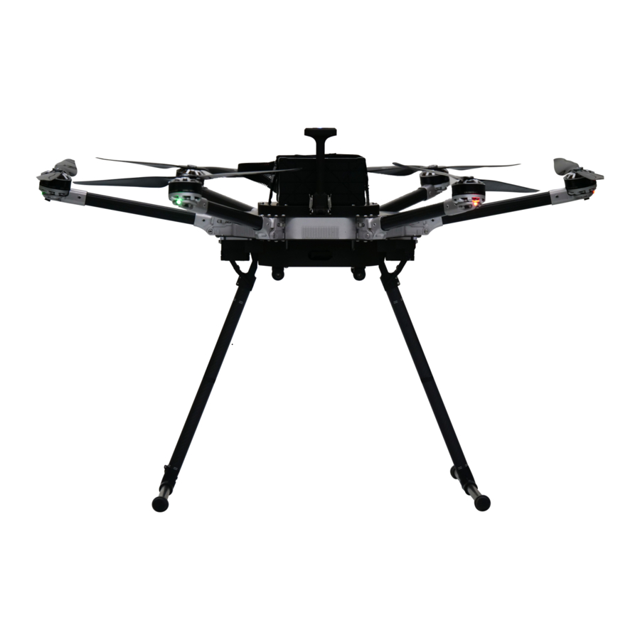
Page 4: Aircraft Overview
1. Product Profile 1.1. Aircraft Overview Each IF1200 comes bound and ready to fly. Listed below are all the various subassemblies included in the kit. -
Page 5: Controller Overview
1.2. Controller Overview Jeti DS-12 Controller (Default Switch Assignment) Note: Switches not labelled are not programmed for standard use, but can be customized to conduct any Mavlink commands. -
Page 6: Herelink Controller
Herelink Controller (Default Button Assignment) Note: Switches labeled as ‘Disabled’ are not programmed for standard use, but can be customized to conduct any Mavlink commands... -
Page 7: Tattu Ta1200 Battery Charger
2. Charging the Batteries 2.1. Tattu TA1200 Battery Charger... -
Page 8: Battery Charging Instructions
Battery Charging Instructions Plug in the charger unit using the power cable included. Make sure the charger is plugged into a 110v power source. Press the power button on the side of the battery charger to power on the unit. Fans will begin spinning, and the LCD screen on each side of the charger will illuminate. - Page 9 Adjust the charge mode dial. There are three charge mode options: Trickle, Standard, and Fast. If time is not an issue, it is recommended to charge the batteries as slowly as possible for extended battery health. Uncap the battery and plug into one side of the charger. Note: The connector design ensures a mistake can not be made with the connector orientation.
-
Page 10: Balancing Instructions
Once connected, the battery will go through a precharge countdown of 10 seconds, then will begin charging automatically. To skip the precharge countdown, hold the ‘Charge’ button for 2 seconds. Cell voltages and battery levels will be indicated on the LCD screen. Balancing Instructions When the battery is connected to the charger, individual cell voltages will be displayed on the LCD screen. -
Page 11: Set-Up Aircraft
3. Setup Instructions 3.1. Set-Up Aircraft Ensure that you have a flat, fairly clean surface to set the vehicle down on while you assemble the landing gear. If you don’t have that surface, the job is much easier with two people. - Page 12 Lift the GPS mast into place, latching the clips on both sides. Unfold the six aircraft arms into upright position. The shoulders should lock the arms securely into place.
- Page 13 Locate the assembled landing gear. Insert the landing gear legs into the corresponding sockets on the underside of the vehicle. Ensure the notch in the end of the tube is aligned with the notches inside the socket. Again, ensure the vertical tube is fully seated before tightening the ratcheting clamp. The ratcheting arm can be pulled away from the screw to move the arm to a more convenient location when tightening.
-
Page 14: Installing Batteries
3.2. Installing Batteries Ensure the velcro straps on top of the vehicle are unfastened and moved out of the way so that the battery can be placed on top of the vehicle. Lay the battery on the foam pads on the top plate of the vehicle, ensuring: The battery is oriented such that the battery’s indicator lights and cables are towards the rear of the vehicle. - Page 16 Locate the battery straps and loop the ends through themselves over the body of the battery. The plastic loop should be close to the center of the battery. Pull the straps tightly over the battery, securing the velcro strap to itself close to the body Note: of the vehicle.
- Page 17 Plug in the male battery connector on the battery into the female battery connector on the aircraft. Note: The connector design ensures a mistake can not be made with the connector orientation. WARNING: Ensure the connectors are pushed together fully. Failure to do so could lead to arcing inside the connector, damaging it.
-
Page 18: Setting Up Ground Station (Jeti Ds-12)
The following instructions are for the Jeti DS-12 / Microhard setup only. If you are using a Herelink controller, skip to the next section. Inspired Flight has tested and recommends using QGroundControl on a PC, Mac, or Android tablet ground-station. For instructions on installing QGroundControl, see Section 4 .1... - Page 19 3. Restart Windows (If VPN was disabled) 4 . Open Control Panel 5. Select ‘Network and Internet’ 6. Select ‘Network and Sharing Center’ 7. Select ‘Change adapter settings’ on the left side bar 8. Unplug and plug in the included ethernet cable (attached to the powered Microhard) into the PC.
- Page 20 9. Highlight 'Internet Protocol Version 4 (TCP/ IPv4)' and select ‘Properties’ 10. Select 'Use the following IP address:' IP address: 192.168.168.101 Subnet mask: 255.255.255.0 11. Select ‘OK’ 12. Ensure all steps from ‘Hardware Setup’ section above are complete 13. The ground station is now configured to connect to the aircraft.
- Page 21 If using an Android Tablet Ground Station: Hardware Setup: Necessary hardware (all except tablet are included): Microhard Antennas 2. Microhard 3. Android Tablet 4 . USB-Mini Cable 5. USB-A to USB-C Cable 6. USB-C Hub 7. USB-C 90 Degree Extension 8.
- Page 22 Setup Steps: Connect tablet mount (10) to Jeti DS-12 controller (11) using the included thumb screw (14). Tighten with a flat-head screwdriver. 2. Connect USB-A to USB-C cable (5) into battery pack (12).
- Page 23 3. Connect Microhard power cable (9) into battery pack (12). 4 . Place battery pack (12) onto rear of Jeti DS-12 controller (11), ensuring the connected cables are facing the top of the controller.
- Page 24 5. Connect USB-C 90 degree extension (7) into USB-C hub (6). 6. Connect USB-Mini cable (4) to the first USB port of the USB-C hub (6).
- Page 25 7. Connect ethernet cable (8) to the end of the USB-C hub (6). 8. Place the USB-C hub (6) onto the velcro pad on the base of the tablet mount (10).
- Page 26 9. Connect antennas (1) into Microhard (2). 10. Loosen the plastic nut on the rear of the tablet mount (10) and rotate the mount such that the spring-loaded half of the mount is facing up.
- Page 27 11. Fix the Android tablet (3) into the tablet mount (10) by pulling the spring loaded portion away from the controller. 12. Plug in the Microhard power cable (9) into the Microhard (2).
- Page 28 13. Plug in the ethernet cable (8) into the Microhard (2). Note: We recommend running these cables between the tablet mount and controller, as the cable management will be much cleaner.
- Page 29 14 . Place the Microhard (2) on the velcro pad at the top of the tablet mount (10). The antennas should be parallel, facing up. 15. Plug in the USB-C hub (6) and 90 degree extension (7) into the android tablet (3).
- Page 30 16. Plug in the USB-C to USB-A cable (5) into the USB-C hub (6). 17. Plug in the USB-mini cable (4) into the Jeti controller (11).
- Page 31 18. Upon plugging in the Jeti controller (11), the screen will light up and prompt ‘Start Transmitter?’ Select ‘Yes’ (the rightmost button) to power on the controller. 19. The controller will then prompt ‘Connect USB?’ Select ‘Yes’ (the rightmost button) to run all communications through the USB ground station.
- Page 32 Once complete, this screen will be displayed on the controller. 20. Connect the included neck strap (13) to the center loop of the controller (11).
- Page 33 21. Upon unlocking the tablet, the tablet will prompt you to open QGroundControl when the USB device is connected. Press ‘Always open’, then ‘OK’. The hardware for the Android tablet ground station is now fully set-up. The ground station is now fully assembled and physically ready to use.
- Page 34 Software Setup: Open settings app on the android tablet, and navigate to the wifi settings. Click on ‘More connection settings’. 2. If ethernet is already ‘Connected’, disconnect using the blue switch. 3. Click on ‘Configure ethernet device’ 4 . Click on ‘Static IP’ and enter the following credentials: IP Address: 192.168.168.101 Netmask: 255.255.255.0 DNS Address: 192.168.168.1...
- Page 35 Click ‘Save’. 5. Turn the ethernet back on to connect. 6. Ensure all steps from ‘Hardware Setup’ section above are complete 7. The ground station is now configured to connect to the aircraft. If using a Mac Ground Station: Click on the apple icon, then click on ‘System Preferences’...
- Page 36 2. Open ‘Network’ 3. In the network settings select ‘TCP/ IP’, then set ‘Configure IPv4’ to ‘Manually’. Under ‘IPv4 Address’ enter: 192.168.168.101 Under ‘Subnet Mask’ enter: 255.255.255.0...
- Page 37 4 . Accept setting changes and close ‘System Preferences’ 5. Ensure all steps from ‘Hardware Setup’ section above are complete 6. The ground station is now configured to connect to the aircraft.
-
Page 38: Set-Up Fpv Camera
3.4. Set-Up FPV Camera All aircrafts come with an FPV camera preinstalled. However, only one video stream can currently be passed through to QGC at a time, so if a Gremsy gimbal is installed on the aircraft, please follow the steps in Section 2.5 to enable a video stream from the prioritized payload camera. -
Page 39: Set-Up Payload Camera
3.5. Set-Up Payload Camera If the aircraft has been configured with a Gremsy gimbal, first follow the instructions below from Gremsy to attach the gimbal to the aircraft via the quick-disconnect. - Page 40 Next, use the following instructions from Gremsy to balance the camera on the Gremsy gimbal.
- Page 44 Lastly, use the following steps to set up video streaming from the camera mounted on the gimbal to QGroundControl. In QGC, click on the purple ‘Q’ button on the top left of the screen, then click on ‘Application Settings’ 2. At the top of the page in the ‘Video’ section, under the ‘Source’ drop-down select ‘MPEG-TS (h.264) Video Stream’.
-
Page 45: Powering On Vehicle
3.6. Powering On Vehicle To power the IF1200, press and hold the silver power button on the chassis at the rear of the vehicle. The LED indicator light will turn on when the aircraft is on, and beeping will occur during the initialization sequence. The LED on the GPS mast will begin breathing blue as it searches for a GPS signal. -
Page 46: Power On Controller
When return mode is activated, the IF1200 will automatically return to its home position and land. The home position is set by the location where the IF1200 is armed. If the drone is below an altitude of 30 meters, it will first rise to 30 meters before returning to its home position in a straight line. -
Page 47: Opening Qgroundcontrol
Caution: The IF1200 is automatically set to return to launch as a failsafe when the battery voltage gets too low to continue flight; however, keep an eye on the battery level in QGC and replace the batteries conservatively to mitigate risk. - Page 48 2. Vehicle setup ---> Configure and adjust tuning for the UAV. Adjusting these settings are not recommended without consulting Inspired Flight and may cause any warranty to be voided. All vehicles are tuned for optimal performance prior to customer delivery.
- Page 49 The main screen on QGC has 2 main pages. Switch back and forth between them by clicking on the corresponding icon in the top left corner of the screen. Plan This screen is used to plan and upload autonomous missions to the UAV. Individual waypoints can be added and configured to plan a mission.
-
Page 50: Calibrating Joysticks
3.10. Calibrating Joysticks Because the signals for video transmission, telemetry, and control are all transmitted through the Microhard via USB, it is important to set this up in QGC. Open QGC with the vehicle and ground-station fully set-up and connected. 2. - Page 51 4 . Click on the ‘Joystick’ tab. 5. Click on ‘Calibration’, then ‘Start’.
- Page 52 6. Follow the steps shown in the graphic of the two sticks. Once complete, hit ‘Next’. 7. Select the ‘Button Assignment’ tab. The goal is to set the following button channels: Position Disarm Altitude Return 8. Now map the Jeti DS-12’s switches. Flipping each switch will highlight the channel in QGC, helping to see which channels are mapped to which switch.
- Page 53 the switches shown below to the corresponding command. Note that the vehicle will not disarm unless it is on the ground. 9. Finally, go into the ‘Parameters’ tab in ‘Vehicle Setup’ and search for ‘COM_RC_IN_MODE’. This must be changed to ‘Joystick/ No RC Checks’. 10.
-
Page 54: Calibrating The Compass
3.11. Calibrating the Compass When the drone is transported between flight locations (more than 300 miles), it could be necessary to recalibrate the compass to account for changes in magnetic field strength. This process can be accomplished through the Vehicle Setup menu highlighted below. - Page 55 After hitting ‘OK’, the drone must be rotated about a vertical axis (the human body) for seven seconds in each of the orientations shown. Green boxes show complete orientations, the yellow box shows current calibrating orientation, and red boxes indicate incomplete orientations. Hold the drone steady until the orientation highlights yellow in QGC 2.
-
Page 56: Installing Propellers
Locate the correct propeller for each motor. As seen in the photo below, three of the IF1200’s motors will spin clockwise, and three will spin counterclockwise. The two motor and prop types have keyed quick-disconnects that prevent a user from mounting the wrong propeller on the wrong motor. - Page 57 Ensuring the screws line up with the corresponding screw holes on the motor, place each propeller on its motor. Make sure each propeller is fully seated, with the aluminum quick-disconnect resting on the motor itself. Tighten the propellers onto the motors, ensuring not to over-tighten. We recommend using the provided torque screwdriver to attain the proper torque specification.
- Page 58 When the propellers are mounted correctly, the propellers should be parallel to the top surface of the motor, and everything should be fully seated and firmly secured.
-
Page 59: Arming And Takeoff
If the drone begins to tip over on takeoff, immediately lower the throttle and disarm. If this occurs, it is likely that a propeller was installed on a wrong motor, or an ESC is not calibrated properly. Contact Inspired Flight for diagnostic instructions. - Page 60 place until the pilot lands the vehicle in a manner described in the previous paragraph. The vehicle will automatically disarm after landing. The propellers will stop spinning when the drone disarms. 2. Disconnect the battery. (It is best to pull from the connector and not the wires to increase the life of the battery.) 3.
-
Page 61: Planning An Autonomous Mission
3.15. Planning an Autonomous Mission Once the pilot is comfortable with flying the aircraft at a basic level, planning an autonomous mission is a very useful feature to learn. The following information and images have been gathered from QGroundControl’s site, which can be referenced for any additional information. - Page 62 Note: Max telem dist is the distance between the Planned Home and the furthest waypoint. Upload Button: When planning is complete, use this button to upload the plan to the vehicle. Plan Tools: Used to create and manage missions. Mission Command List/Overlay: Displays the current list of mission items (select items to edit).
- Page 63 The Fly View displays the actual home position set by the vehicle firmware when it arms (this where the vehicle will return in Return/ RTL mode). Plan Tools The plan tools are used for adding individual waypoints, easing mission creation for complicated geometries, uploading/ downloading/ saving/ restoring missions, and for navigating the map.
- Page 64 and rally points. Within the list you can select individual mission items to edit their values. Mission Settings The ‘Mission Start’ panel is the first item that appears in the mission command list. It may be used to specify a number default settings that may affect the start or end of the mission.
- Page 65 This is only the planned home position and you should place it where you plan to start the vehicle from. It has no actual impact on flying the mission. The actual home position of the IF1200 is set by the vehicle itself when arming.
-
Page 66: Motor Navigation Lights
If you are planning a mission while you are connected to a vehicle the firmware and vehicle type will be determined from the vehicle. This section allows you to specify the vehicle firmware/ type when not connected to the IF1200. The additional value that can be specified when planning a mission is the vehicle flight speed. -
Page 67: Installing Qgroundcontrol
Assuming all hardware and software setup steps (Section 2.2) have been followed correctly, the Inspired Flight UAV will automatically connect to QGC once the vehicle has been powered on. Instructions on setting up the vehicle will be found later on. - Page 68 Entire Loss of Vehicle: If a flyaway or battery depletion away from the home point occurs, follow the FAA guidelines on vehicle loss, and contact Inspired Flight for further instruction. Vehicle Crash: If the aircraft is flown into an obstruction or crashes for any reason, follow the procedure in the FAA guidelines, and contact Inspired Flight for further instruction.
- Page 69 4.5. Upgrading the Firmware Note: Firmware upgrades are only necessary if advised by Inspired Flight. The aircraft comes with factory firmware preinstalled. With the drone powered off, open QGC on a PC. 2. Click on the settings button, then the ‘Firmware’ tab.
- Page 71 4.6. Focusing the FPV Camera If the FPV camera ever seems blurry, the lens focus can be adjusted. The FPV camera has a twist-on/ off lens that can be adjusted with a pair of tweezers. Note the two flat spots on either side of the lens: While watching the FPV video stream, carefully use a pair of sharp tweezers to turn the lens until it is in focus.
- Page 73 Preflight Checklist ❏ All four arms are lifted and secured into place ❏ The GPS mast(s) is(are) lifted and latched on both sides ❏ The propellers are mounted in the proper locations and are secured tightly ❏ The antennas are plugged into the top of the controller (if using a Herelink controller) ❏...
Need help?
Do you have a question about the IF1200 and is the answer not in the manual?
Questions and answers