Table of Contents
Advertisement
Advertisement
Table of Contents
Troubleshooting

Related Manuals for IBM ServeRAID


Summary of Contents for IBM ServeRAID
- Page 1 IBM ServeRAID User’s Reference, Version 5.10 SC33-P263-60...
- Page 2 Appendix B, “Warranty information” on page 183 and Appendix C, “Notices” on page 195. Fifth Edition (July 2002) © Copyright International Business Machines Corporation 2002. All rights reserved. US Government Users Restricted Rights – Use, duplication or disclosure restricted by GSA ADP Schedule Contract with IBM Corp.
- Page 3 Lees voordat u dit product installeert eerst het boekje met veiligheidsvoorschriften. Les heftet om sikkerhetsinformasjon (Safety Information) før du installerer dette produktet. Antes de instalar este produto, leia o folheto Informações sobre Segurança. Перед установкой продукта прочтите брошюру по технике безопасности (Safety Information). © Copyright IBM Corp. 2002...
- Page 4 Pred inštaláciou tohto produktu si pre ítajte Informa nú brožúrku o bezpe nosti. Preden namestite ta izdelek, preberite knjižico Varnostne informacije. Antes de instalar este producto, lea la Información de Seguridad. Läs säkerhetsinformationen innan du installerar den här produkten. IBM ServeRAID: User’s Reference, Version 5.10...
- Page 5 Statement 2 CAUTION: When replacing the lithium battery, use only IBM Part Number 33F8354 or an equivalent type battery recommended by the manufacturer. If your system has a module containing a lithium battery, replace it only with the same module type made by the same manufacturer.
- Page 6 The device also might have more than one power cord. To remove all electrical current from the device, ensure that all power cords are disconnected from the power source. IBM ServeRAID: User’s Reference, Version 5.10...
-
Page 7: Table Of Contents
Notices that are used in this book ....xii IBM ServeRAID Support CD ....xiii Supported operating systems. - Page 8 Terms and definitions ..... . 107 ServeRAID considerations ....108 Chapter 13.
- Page 9 Creating diskettes on Windows ....180 Creating diskettes on IBM OS/2 ....180 Creating diskettes on Linux or UNIX .
- Page 10 IBM ServeRAID: User’s Reference, Version 5.10...
-
Page 11: Preface
ServeRAID utility programs and the IBM ServeRAID Cluster Solution. Note: The IBM ServeRAID product can be either a controller on an adapter, such as the one in this option package, or a controller on the system board of your server. -
Page 12: Notices That Are Used In This Book
Chapter 19, “Getting help and technical assistance” on page 175 provides information about accessing the IBM World Wide Web sites to obtain future code and information updates for the ServeRAID controller. Appendix A, “Creating ServeRAID diskettes” on page 179 contains instructions for creating the IBM ServeRAID Support diskettes, which contain device drivers and the IPSSEND utility program. -
Page 13: Ibm Serveraid Support Cd
If the BIOS and firmware code need updating, the wizard will give you the opportunity to do so. Device drivers The device drivers are located in the following directory on the IBM ServeRAID Support CD: e:/operatingsystem/DRIVER where e is the CD-ROM drive and operatingsystem is the specific operating system used in the ServeRAID installation. - Page 14 IBM ServeRAID Failover Support for Windows NT 4.0 and Windows 2000 diskette v IBM ServeRAID Cluster Solution for Windows NT 4.0 and Windows 2000 diskette v IBM ServeRAID Support for Windows 2000 Server diskette v IBM ServeRAID Support for Windows (Professional Editions) diskette v IBM ServeRAID Support for Windows NT 4.0 diskette...
-
Page 15: Supported Operating Systems
Linux in the /BOOKS/READERS directory. If you are installing the IBM ServeRAID Cluster Solution, you might need to refer to the IBM Shared Disk Clustering Hardware Reference. This book provides general information about planning and configuring a shared-disk cluster using IBM server products. - Page 16 IBM ServeRAID: User’s Reference, Version 5.10...
-
Page 17: Part 1. Installation And Configuration
Part 1. Installation and configuration © Copyright IBM Corp. 2002... - Page 18 IBM ServeRAID: User’s Reference, Version 5.10...
-
Page 19: Chapter 1. Product Information
(See “Controller features” for more information.) ™ You also can use the IBM ServeRAID Manager program with an IBM xSeries server that contains an integrated SCSI controller with RAID capabilities. Hereafter, these controllers are referred to as integrated RAID controllers. -
Page 20: Connector Locations
15 physical devices. Note: In the event of a power outage or failure, the battery-backup cache protects the data stored in the ServeRAID cache memory when using the write-back setting of the write-cache mode. IBM ServeRAID: User’s Reference, Version 5.10... - Page 21 Channel 2, Channel 3, and Channel 4 connectors. You cannot attach internal and external SCSI devices to the same channel. For example, you cannot attach devices to both external Channel 1 and internal Channel 1. The ServeRAID-4 controllers do not support configurations that use both the internal and external connectors on the same channel concurrently.
- Page 22 Channel 1 and Channel 2. Each of these SCSI channels supports up to 15 physical devices. Note: In the event of a power outage or failure, the battery-backup cache protects the data stored in the ServeRAID cache memory when using the write-back setting of the write-cache mode. Internal Channel 1...
- Page 23 Statement 2 CAUTION: When replacing the lithium battery, use only IBM Part Number 33F8354 or an equivalent type battery recommended by the manufacturer. If your system has a module containing a lithium battery, replace it only with the same module type made by the same manufacturer.
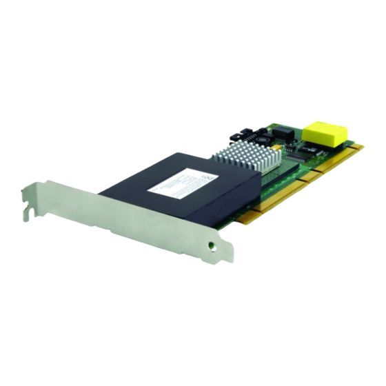
- Page 24 The ServeRAID-5i controller has no independent SCSI channel connectors. It must be used with an IBM xSeries server that contains an integrated RAID controller. It comes with both a 2-U and 3-U I/O bracket; the 3-U bracket is mounted on the controller.
- Page 25 Statement 2 CAUTION: When replacing the lithium battery, use only IBM Part Number 33F8354 or an equivalent type battery recommended by the manufacturer. If your system has a module containing a lithium battery, replace it only with the same module type made by the same manufacturer.
- Page 26 IBM ServeRAID: User’s Reference, Version 5.10...
-
Page 27: Chapter 2. Installing And Cabling A Serveraid Controller
Using Windows NT 4.0 with Active PCI features To use Active PCI with Windows NT 4.0 and a ServeRAID controller, you must install the following software components in this order: 1. DMI Service provider. A free version is included on the IBM ServeRAID Support CD in the following directory: e:\WINNT\DMISP\setup.exe... -
Page 28: Installing The Serveraid-4 Controller
2. IBM Hot Plug for Windows NT 4.0 Package, version 4.2 or later. This package is available from the IBM Support Web site. See “Downloadable files from the World Wide Web” on page 141 for additional information. Note: Be sure to read the instructions and restrictions for this software program. - Page 29 Review the documentation provided with your operating system for information concerning using these features. v See “Using a ServeRAID controller in a server with Active PCI features” on page 11. 2. If your server model does not support Active PCI, turn off the server and disconnect all power cords and cables from the server.
- Page 30 13 on page 15. Otherwise, go to step 10. 10. Connect one end of a 68-pin standard cable (separately purchased or already in your server) to the internal channel connector on the ServeRAID controller. Note: See “Connector locations” on page 4 for the channel connector locations.
- Page 31 See your server documentation if you need detailed instructions. 15. If you want to attach an external SCSI device to the ServeRAID controller, go to “Connecting external devices to a ServeRAID-4 controller”. Otherwise, go to Chapter 3, “Understanding RAID technology”...
-
Page 32: Installing The Serveraid-5I Controller
If you plan to install a ServeRAID-5i controller into a server that contains data, back up the data first. When the ServeRAID-5i controller is installed, you will lose access to any data or applications on physical drives connected to the integrated RAID controller. - Page 33 4. To remove the battery, gently press the tab up and lift the battery away from the controller. Figure 8. Removing the battery from a ServeRAID-5i controller 5. Remove the two bracket screws. Set them aside. 6. Remove the 3-U bracket.
- Page 34 3. Remove the server cover and locate the PCI expansion slot. Notes: a. The ServeRAID-5i controller must be installed in an extended PCI expansion slot. If you have not already done so, see the documentation that comes with your server to determine the correct PCI expansion slot for the ServeRAID-5i controller.
- Page 35 9. If you have physical drives to install, install them now. See your server documentation for drive installation instructions. 10. Install the server cover. 11. Reconnect the cables and cords. See your server documentation if you need detailed instructions. Chapter 2. Installing and cabling a ServeRAID controller...
- Page 36 IBM ServeRAID: User’s Reference, Version 5.10...
-
Page 37: Chapter 3. Understanding Raid Technology
This grouping technique greatly enhances logical-drive capacity and performance beyond the physical limitations of a single physical drive. When you group multiple physical drives into a logical drive, the ServeRAID controller can transfer data in parallel from the multiple drives in the array. This parallel transfer yields data-transfer rates that are many times higher than with nonarrayed drives. -
Page 38: Selecting A Raid Level And Tuning Performance
Generally, the more drives in the array, the better the performance. Supported RAID levels The ServeRAID controllers support RAID level-0, level-1, level-1E, level-5, level-5E, level-00, level-10, level-1E0, and level-50. The integrated RAID controllers support RAID level-1 only. The ServeRAID-5i controller does not support RAID level-5E. - Page 39 Understanding RAID level-0 RAID level-0 stripes the data across all the drives in the array. This offers substantial speed enhancement but provides no data redundancy. RAID level-0 provides the largest storage capacity of the RAID levels that are offered, because no room is taken for redundant data or data-parity storage.
- Page 40 When you replace a failed drive, the ServeRAID controller can rebuild all the RAID level-1, level-1E, level-5, and level-5E logical drives automatically onto the replacement physical drive. However, any data stored in a failed RAID level-0 logical drive is lost.
- Page 41 Notice that the data on the drive on the right is a copy of the data on the drive on the left. With RAID level-1, if one of the physical drives fails, the ServeRAID controller switches read and write requests to the remaining functional drive in the RAID level-1 array.
- Page 42 Also, notice that each block on the mirror stripe is shifted one drive. With RAID level-1E, if one of the physical drives fails, the ServeRAID controller switches read and write requests to the remaining functional drives in the RAID level-1E array.
- Page 43 The following illustration is an example of a RAID level-5 logical drive. Start with four physical drives. Create an array using three of the physical drives, leaving the fourth as a hot-spare drive. Then create a logical drive within that array.
- Page 44 RAID level-5E, you can have a maximum of seven logical drives on the controller. The following illustration is an example of a RAID level-5E logical drive. Start with four physical drives. Create an array using all four physical drives. IBM ServeRAID: User’s Reference, Version 5.10...
- Page 45 Higher performance than RAID level-5 v Cannot share a hot-spare drive with other arrays Note: The ServeRAID Manager program Configuration wizard does not default to RAID level-5E. If you have four physical drives, Express configuration defaults to RAID level-5 with a hot-spare drive.
- Page 46 Understanding RAID level-x0 Note: RAID level-x0 is available only on the ServeRAID-4 and ServeRAID-5i controllers. RAID level-x0 refers to RAID level-00, level-10, level-1E0, and level-50. RAID level-x0 uses an array of arrays, or a spanned array. The operating system uses the spanned array logical drive in the same way as a regular array logical drive.
- Page 47 RAID level-0 With RAID level-10, level-1E0, and level-50, if one of the physical drives fails in a sub-logical drive, the ServeRAID controller switches read and write requests to the remaining functional drives in the sub-logical drive. With RAID level-00, a physical drive failure within the sub-logical drive results in loss of data.
-
Page 48: Drive-State Descriptions
The ServeRAID controller recognizes a ready drive as being available for definition. Standby hot spare A standby hot spare is a hot-spare drive that the ServeRAID controller has spun down. If an online drive becomes defunct and no suitable hot-spare drive is available, a standby hot-spare drive of the appropriate size automatically spins up and enters the rebuild state. - Page 49 If any of these is true, see “Rebuilding a defunct drive” on page 157. Okay The logical drive is working properly. It is in a good, functional state. System The ServeRAID controller uses this reserved state during logical-drive migration. Chapter 3. Understanding RAID technology...
- Page 50 IBM ServeRAID: User’s Reference, Version 5.10...
-
Page 51: Chapter 4. Configuring Serveraid Controllers
Complete the following steps to locate files: 1. Go to http://www.ibm.com/pc/support/. 2. In the Search field at the top of the page, type ServeRAID; then, press Enter. Note: If you download ServeRAID software, you must download and install all ServeRAID software at the same time. This will ensure that all levels of the software are compatible. -
Page 52: Configuring The Serveraid Controller
For failover, go to Chapter 6, “Configuring two ServeRAID controllers in a failover environment” on page 51. v For clustering, go to Part 3, “Installing the IBM ServeRAID Cluster Solution” on page 101. Using ServeRAID Manager The ServeRAID Manager program operates in two ways:... - Page 53 Complete the following steps to use Express configuration: 1. In the ServeRAID Manager tree, click the ServeRAID controller that you want to configure. 2. Click Express configuration.
- Page 54 7. When you have completed configuring your controllers, you can change certain controller settings. See “Fine-tuning your configuration” on page 43 for more information. If you do not want to change any settings, exit from the ServeRAID Manager program, and remove the CD from the CD-ROM drive.
- Page 55 6. Repeat steps 4 and 5 for each additional array or hot-spare drive that you want to configure. 7. After you select the ready drives for your arrays and hot-spare drive, click Next. The “Create logical drives” window opens. Chapter 4. Configuring ServeRAID controllers...
- Page 56 A logical drive cannot exceed 2048 GB. d. Typically, the first logical drive defined on the first ServeRAID controller found by system BIOS during startup will be your startup (boot) drive. 11. If you have free space available and want to create additional logical drives, click Create new logical drive.
- Page 57 13. Repeat steps 8 on page 40 through 12 for each additional array you want to configure. 14. Click Next. The “Configuration summary” window opens. Figure 15. “Configuration summary” window (Custom Configuration) Chapter 4. Configuring ServeRAID controllers...
- Page 58 ServeRAID Manager program, and remove the CD from the CD-ROM drive. 19. Restart the server. 20. Continue with Chapter 5, “Installing ServeRAID device drivers” on page 49. Note: If you are configuring your startup (boot) ServeRAID controller, you must install the device driver while installing the operating system.
- Page 59 Complete the following steps to change the stripe-unit size: 1. In the ServeRAID Manager tree, click the new controller to select it. 2. Click Actions → Change stripe-unit size. Chapter 4. Configuring ServeRAID controllers...
-
Page 60: Viewing Your Configuration
1. In the ServeRAID Manager tree, click the logical drive. 2. Click Actions → Change write-cache mode to write through. Viewing your configuration You can use ServeRAID Manager to view information about RAID controllers and the RAID subsystem (such as arrays, logical drives, hot-spare drives, and physical drives). -
Page 61: Getting Assistance
Figure 17. ServeRAID Manager window To display available actions for an item, click the item in the ServeRAID Manager tree and click Actions. Getting assistance For more information about ServeRAID Manager, see the online help system. To start the help system, either click (Information about this window) on the toolbar or select an item from the Help menu. - Page 62 To learn more about the ServeRAID Manager tree objects and the actions that apply to them, select a tree object and click Actions → Hints and tips. ServeRAID Assist will start, and information about the tree object will appear in the right pane of ServeRAID Manager.
- Page 63 Figure 19. Hints and tips feature Chapter 4. Configuring ServeRAID controllers...
- Page 64 IBM ServeRAID: User’s Reference, Version 5.10...
-
Page 65: Chapter 5. Installing Serveraid Device Drivers
Caldera UnixWare 7.1.1 v Caldera Open UNIX 8.0 If you are configuring your startup (boot) ServeRAID controller, you must install the device driver while installing the operating system. If you are installing files for a RAID controller that comes as a standard feature on your IBM server system board, use the installation instructions and CDs provided with your server. - Page 66 IBM ServeRAID: User’s Reference, Version 5.10...
-
Page 67: Chapter 6. Configuring Two Serveraid Controllers In A Failover Environment
Two ServeRAID-3L v Two ServeRAID-II Note: If your system has a built-in ServeRAID controller on the system board, you cannot use the built-in controller in the failover pair. To use fault-tolerant technology with ServeRAID controllers, you must use one of... -
Page 68: Preparing The Active Controller
Step 5. Installing the appropriate device driver. Installing the active controller If you have not yet installed the ServeRAID controller that you will designate as the active controller, do so now. For instructions, see the IBM Installation Guide that came with the controller. - Page 69 This point is especially important if the Windows 2000 or Windows NT 4.0 system startup drive is attached to the IBM ServeRAID controller. If this process occurs after the startup-drive array has been created, the array information will be removed, and the system will no longer start in Windows 2000 or Windows NT 4.0.
- Page 70 ServeRAID Manager has successfully restored the configuration to the factory-default settings. 7. In the ServeRAID Manager tree, click the ServeRAID controller that you want to configure as the active controller. 8. Click (Configure for clustering) on the toolbar.
- Page 71 1 on the active controller, and the enclosure bus #2 cable is connected to Channel 1 on the passive controller 2. Restart the server with the IBM ServeRAID Support CD (or the configuration CD that came with your server) in the CD-ROM drive.
- Page 72 Notes: a. You must use all the ready drives when creating your arrays (that is, all ready drives in the ServeRAID Manager tree must be online). b. Hot-spare drives are not supported in a failover environment. The exception is the built-in hot-spare that is part of a RAID level-5E logical drive.
- Page 73 Create only one logical drive for each array. b. A logical drive cannot exceed 2048 GB. c. Typically, the first logical drive defined on the first ServeRAID controller found by system BIOS during startup will be your startup (boot) drive.
- Page 74 14. Click Apply; then, click Yes when asked if you want to apply the new configuration. The configuration is saved in the ServeRAID controller and on the physical drives. 15. Click Continue to return to ServeRAID Manager. After creating the arrays and logical drives, you must assign merge-group numbers to the shared logical drives.
- Page 75 You will need this information to recover the configuration if the ServeRAID controller fails. Note: You can save this information to a file by using the ServeRAID Manager program: a. In the ServeRAID Manager tree, click the server.
- Page 76 Installing the device driver Complete the following steps to finish the active controller installation: 1. Install the fault-tolerant device driver located on the IBM ServeRAID Failover Support for Windows NT and Windows 2000 diskette. This can be done either during or after installing Windows 2000 or Windows NT 4.0. For instructions, see the IBM ServeRAID Device Driver Installation Instructions on the IBM ServeRAID Support CD.
-
Page 77: Preparing The Passive Controller
Preparing the passive controller This section covers the following steps: Step 1. Installing the ServeRAID controller that you will designate as the passive controller. Step 2. Configuring the passive controller for failover. Step 3. Connecting the passive controller to the enclosure; then, starting the server. - Page 78 4. In the ServeRAID Manager tree, click the ServeRAID controller that you want to configure as the passive controller. 5. Click (Configure for clustering) on the toolbar. The “Configure controller 2 for clustering” window opens. Figure 29. “Configure controller 2 for clustering” window 6.
-
Page 79: Completing The Failover Environment Installation
2. Shut down the server. Completing the failover environment installation To verify that the configuration is correct, install and start the ServeRAID Manager program on the Windows 2000 or Windows NT 4.0 server. For more information, see Chapter 10, “Installing and starting the ServeRAID Manager program” on page 93. - Page 80 IBM ServeRAID: User’s Reference, Version 5.10...
-
Page 81: Part 2. Utility Programs
Part 2. Utility programs © Copyright IBM Corp. 2002... - Page 82 IBM ServeRAID: User’s Reference, Version 5.10...
-
Page 83: Chapter 7. Using The Serveraid Mini-Configuration Program
Mini-Configuration program. The ServeRAID Mini-Configuration program provides a quick way to display the current settings for a ServeRAID controller. You also can use this program to perform a limited set of the configuration functions without using the IBM ServeRAID Support CD. -
Page 84: Viewing The Configuration
Restore to Factory Default Settings restores all parameters in the configuration to the factory-default settings. When you reset the configuration, any data or programs stored on the logical drives attached to the selected ServeRAID controller will become inaccessible. IBM ServeRAID: User’s Reference, Version 5.10... - Page 85 Copy the Configuration from Drives to Controller reads the most common configuration from the drives in the server and copies it to the ServeRAID controller. v Configure BIOS Settings is used to modify the following BIOS settings for the ServeRAID controller: –...
- Page 86 IBM ServeRAID: User’s Reference, Version 5.10...
-
Page 87: Chapter 8. Installing And Using The Ipssend Command-Line Program
ServeRAID Support from DOS diskette. This diskette contains the ASPI device driver. Installing IPSSEND for Windows or OS/2 You can install this program for Windows or OS/2 using either the IBM ServeRAID Support CD or the appropriate IBM ServeRAID Support diskette. Installing IPSSEND for Windows or OS/2 from CD... - Page 88 CD-ROM drive that contains the IBM ServeRAID Support CD and c is the drive letter of the drive where the operating system is installed. 5. Remove the CD from the CD-ROM drive.
- Page 89 Enter: copy a:\cmdline\ipssend.nlm c:\nwserver where a is the drive letter of the diskette drive that contains the IBM ServeRAID Support for NetWare diskette, c is the drive letter of the drive where NetWare is installed, and nwserver is the directory where NetWare is installed.
- Page 90 Complete the following steps to install IPSSEND for OpenServer using the IBM ServeRAID Support CD: 1. Start the server. 2. After the operating system starts, insert the IBM ServeRAID Support CD into the CD-ROM drive. IBM ServeRAID: User’s Reference, Version 5.10...
- Page 91 ServeRAID Support for SCO OpenServer diskette: 1. Start the server. 2. After the operating system starts, insert the IBM ServeRAID Support for SCO OpenServer diskette into the diskette drive. 3. Mount the diskette drive. From the console, type the following and press Enter: mount -f S51K /dev/fd0 /mnt where /dev/fd0 is the specific device file for the diskette drive block device.
- Page 92 Complete the following steps to install IPSSEND for UnixWare or Open Unix using the IBM ServeRAID Support CD: 1. Start the server. 2. After the operating system starts, insert the IBM ServeRAID Support CD into the CD-ROM drive. 3. Mount the CD-ROM drive. From the console, type the following and press Enter: mount -F cdfs -r /dev/cdrom/cdromdevicefile /mnt where cdromdevicefile is the specific device file for the CD-ROM block device.
-
Page 93: Starting The Ipssend Command-Line Program
Starting IPSSEND from DOS Complete the following steps to start IPSSEND: 1. Insert the IBM ServeRAID Support for DOS diskette into the diskette drive. 2. Restart the server. 3. Type the following and press Enter: a:\ipssend where a is the diskette drive letter. - Page 94 FlashCopy function (for Windows only) Note: The ServeRAID-5i controller does not support the FlashCopy function. The FlashCopy function creates a quick backup copy of data. It sets up a link between the source and target partitions; then, it creates a snapshot-like backup of the source data on the target partition.
- Page 95 Important Before using FlashCopy, consider the following: v The source and target partitions must be on the same controller. v You can have up to four FlashCopy links active at one time. v There is no limit on source and target partition size. However, the size of the target partition must be equal to or larger than that of the source partition.
- Page 96 The link between each source v controller is the ServeRAID controller number (1–12) partition and target partition exists until all v source is the source partition number, and target is the data is copied; then, the operation is the target partition number.
- Page 97 ServeRAID controller number (1–12) configuration. v ALL specifies that all logical drives are to be imported Notes: v n is the logical drive number (1–8) for the specific 1.
- Page 98 Command flashcopy This function lists the following information IPSSEND FLASHCOPY controller MAP for each operating-system partition: where controller is the ServeRAID controller number v Partition number, letter, and size (1–12). v Logical drive number v Array letter If a partition is not available for FlashCopy, the report...
- Page 99 ServeRAID controller number (1–12) target partitions. The snapshot exists only v source is the source partition number, and target is while there is a link between the source the target partition number.
- Page 100 Because this v controller is the ServeRAID controller number (1–12) function runs in the background, you can v logicaldrive is the logical drive number (1–8) use the logical drive immediately.
- Page 101 IPSSEND SYNCH controller DRIVE/GROUP scopeid information on redundant logical drives. If where: the parity information is inconsistent, v controller is the ServeRAID controller number (1–12) IPSSEND repairs it automatically. v DRIVE is a single logical drive v GROUP is a merge group v scopeid is one of the following: –...
- Page 102 ServeRAID controller number (1–12) logs). v DEVICE is the device event log v SOFT is the ServeRAID controller soft event log v HARD is the ServeRAID controller hard event log v ALL is the ServeRAID controller device event, soft...
- Page 103 ServeRAID controller number (1–12) v DEVICE is the device event log v SOFT is the ServeRAID controller soft event log v HARD is the ServeRAID controller hard event log v ALL is the ServeRAID controller device event, soft...
- Page 104 [NOPROMPT] channel and SCSI ID of the physical where: drives. v controller is the ServeRAID controller number (1–12) Note: You cannot create RAID level-x0 v NEWARRAY indicates that you are creating a new logical drives with this function. array and logical drive After the logical drive is created, a quick v ARRAYID is the Array ID (A–H) of the existing array...
- Page 105 IPSSEND GETCONFIG controller AD/LD/PD/AL controller, logical drive, or physical drive. where: This information potentially includes (but v controller is the ServeRAID controller number (1–12) is not limited to) the following: v AD specifies the controller information. v Controller type v LD specifies the logical drive information.
- Page 106 IPSSEND UNATTENDED controller ON/OFF unattended mode. This controller setting where: determines how the BIOS handles failures v controller is the ServeRAID controller number (1–12) during system startup. v ON enables the feature v OFF disables the feature Supported operating systems: Windows, NetWare, OS/2, Linux, OpenServer, UnixWare, Open UNIX, and DOS IBM ServeRAID: User’s Reference, Version 5.10...
-
Page 107: Chapter 9. Using The Ipsmon Command-Line Program (Netware Only)
This chapter provides the information about installing, starting, and using the IPSMON command-line program. You can use the IPSMON program to monitor a ServeRAID controller for defunct drives, Predictive Failure Analysis (PFA) warnings, rebuild operations, FlashCopy operations, synchronizations, logical-drive migrations, and RAID level-5E compressions. - Page 108 <Date and Time> INF006:A1C-SID-- (migration completed) Warning Messages: <Date and Time> WRN001:A2C3SID12 (PFA error detected) Critical Messages: <Date and Time> CRT001:A3C2SID04 (dead drive detected) <Date and Time> CRT002:A1C-SID-- (controller is not responding to commands) IBM ServeRAID: User’s Reference, Version 5.10...
-
Page 109: Chapter 10. Installing And Starting The Serveraid Manager Program
Open UNIX “Installing ServeRAID Manager on UnixWare or Open UNIX” on page 97 If you are installing ServeRAID Manager on an IBM xSeries server that contains an integrated RAID controller, see the documentation provided with your server for a list of supported operating systems. - Page 110 ServeRAID controllers. 2. When installed on Windows Millennium Edition (Me), Windows 98, and Windows 95, the ServeRAID Manager program works only as a console. You can use the console to connect to remote servers that contain ServeRAID controllers. Servers installed with Windows Me, Windows 98, or Windows 95 as the operating system do not support ServeRAID controllers.
- Page 111 1. The ServeRAID Manager program comes with the IBM Java Runtime Environment (JRE). 2. If the ServeRAID Manager program has previously been installed on your server, you must remove that version before upgrading. All customization files (such as Managed system tree nodes and the Notification list) are saved and used in the upgrade.
- Page 112 2. To install or remove the ServeRAID Manager package, you must have root privileges. 3. If ServeRAID Manager is installed on your system, you must remove the old version before upgrading. All customization files (such as Managed system tree nodes and the Notification list) are saved and used in the upgrade. To remove...
-
Page 113: Starting The Serveraid Manager Program
2000, Windows NT 4.0, Windows Me, Windows 98, or Windows 95 To start the ServeRAID Manager program in Windows 2000, Windows NT, Windows Me, Windows 98, or Windows 95, click Start → Programs → ServeRAID Manager → ServeRAID Manager. The ServeRAID Manager program opens, and a window similar to the following appears. - Page 114 To start the ServeRAID Manager program in NetWare: 1. From the NetWare console, type the following and press Enter: LOAD RAIDMAN 2. The ServeRAID Manager program opens, and a window similar to that shown in Figure 31 appears. Starting the ServeRAID Manager program in OS/2 To start the ServeRAID Manager program from the OS/2 desktop, double-click the ServeRAID Manager icon.
- Page 115 2. Press Enter. 3. Type the following and press Enter: sh RaidMan.sh 4. The ServeRAID Manager program opens, and a window similar to that shown in Figure 31 appears. Note: (UnixWare and Open UNIX only) When installed on UnixWare or Open...
- Page 116 IBM ServeRAID: User’s Reference, Version 5.10...
-
Page 117: Part 3. Installing The Ibm Serveraid Cluster Solution
Part 3. Installing the IBM ServeRAID Cluster Solution © Copyright IBM Corp. 2002... - Page 118 IBM ServeRAID: User’s Reference, Version 5.10...
-
Page 119: Chapter 11. Introduction To The Ibm Serveraid Cluster Solution
The IBM ServeRAID Cluster Solution, as discussed in this book, uses one of the following controllers: v IBM ServeRAID-4H Ultra160 SCSI controller... - Page 120 Shared Channel 1 - SCSI ID 6 v Non-shared Channel 2 - SCSI ID 7 Note B: Server B v Shared Channel 1 - SCSI ID 7 v Non-shared Channel 2 - SCSI ID 7 IBM ServeRAID: User’s Reference, Version 5.10...
- Page 121 For more information about requirements and types of installations, see the IBM Shared Disk Clustering Hardware Reference. You can obtain this publication from the IBM Support Web site. See Chapter 16, “Obtaining ServeRAID updates” on page 141 for additional information.
- Page 122 IBM ServeRAID: User’s Reference, Version 5.10...
-
Page 123: Chapter 12. Preparing To Install Or Change A Cluster Solution
Note: If you are going to upgrade an existing high-availability cluster solution and are already familiar with the concepts of a cluster, go to “Updating the ServeRAID BIOS, firmware, and software code for clustering” on page 141. If you are setting up a high-availability cluster solution for the first time, continue reading this section. -
Page 124: Serveraid Considerations
Server B, to ID 7. The setup instructions describe this in more detail. v You must set the stripe-unit size of each ServeRAID controller in a pair to the same value (8 KB, 16 KB, 32 KB, or 64 KB). - Page 125 – RAID level-5 or level-5E logical drives in a critical state However, all other logical drives will failover if necessary. v The ServeRAID controller does not permit the failover of RAID level-5 or level-5E logical drives that are in a critical state. For this reason, do not use RAID level-5 or level-5E for the quorum drive.
- Page 126 IBM ServeRAID: User’s Reference, Version 5.10...
-
Page 127: Chapter 13. Configuring Serveraid Controllers For Clustering
Chapter 13. Configuring ServeRAID controllers for clustering Before configuring the ServeRAID controllers, you must first install the BIOS and firmware code. For more information, see “Updating the ServeRAID BIOS, firmware, and software code for clustering” on page 141. Configuring the controller for Microsoft Cluster Server using Windows 2000 or Windows NT 4.0... -
Page 128: Configuring A Controller For Clustering
Note: For complete information on using the ServeRAID Manager program, see the ServeRAID Manager online help. 1. Insert the IBM ServeRAID Support CD into the CD-ROM drive; then, turn on the server. The ServeRAID Manager program starts. 2. If the ServeRAID Manager program detects unconfigured ServeRAID controllers and ready drives, the program automatically starts the Configuration wizard, and a window similar to the following opens. -
Page 129: Configuring Serveraid Arrays And A Logical Drive
ServeRAID Manager has successfully restored the configuration to the factory-default settings. 6. In the ServeRAID Manager tree, click the ServeRAID controller that you are configuring. 7. Click (Configure for clustering) on the toolbar. The “Configure for clustering”... - Page 130 Complete the following steps to configure arrays and logical drives: 1. Click (Configure RAID) on the toolbar. The Configuration wizard opens. 2. In the ServeRAID Manager tree, click the ServeRAID controller that you want to configure. 3. Click Custom configuration.
- Page 131 Hot-spare drives are not shared between controllers in a cluster pairing. If you want hot-spare protection, each ServeRAID controller must have a hot-spare drive defined. c. You must connect hot-spare drives only to shared channels. Both servers must be able to access their uniquely-defined hot-spare drives in case a failover occurs after a hot-spare drive replaces a failed shared drive.
- Page 132 The configuration is saved in the ServeRAID controller and on the physical drives. 12. Click Return to the ServeRAID Manager to continue working with your ServeRAID configuration. After creating the arrays and logical drives, you must assign merge-group numbers to the shared logical drives.
- Page 133 You will need this information to recover the configuration if the ServeRAID controller fails. Note: You can save this information to a file by using the ServeRAID Manager program: a. In the ServeRAID Manager tree, click the server.
- Page 134 IBM ServeRAID: User’s Reference, Version 5.10...
-
Page 135: Chapter 14. Installing The Microsoft Cluster Server Software
Before installing MSCS, you must install the ServeRAID Manager program: 1. If the server is not running, turn on the server. 2. Insert the IBM ServeRAID Support CD into the CD-ROM drive of Server A. The ServeRAID Manager setup program starts. - Page 136 When you are finished, return to this step and continue with this procedure. 2. Use the ServeRAID Manager program to scan for new drives on both servers. Right-click on the controller, and click Scan for new or removed ready drives.
- Page 137 MSCS software. Server B will restart when the installation is completed. 10. Install the IBM ServeRAID Windows NT Cluster Solution program by doing the following: a. On Server A, run the utility SETUP.EXE program from the IBM ServeRAID...
- Page 138 Creating additional ServeRAID disk resources on a Windows NT 4.0 ServeRAID cluster You can use a ServeRAID logical disk that has not already been designated as a cluster resource, or you can create a new array and logical disk on Server A, using the ServeRAID Manager program.
- Page 139 1. On the server owning the newly created logical drive, run the Cluster Administration program and open a connection to the installed cluster. 2. To create the ServeRAID disk resource in an existing group, ensure that the cluster server that owns the shared logical drive is the owner of that group. If...
- Page 140 10. After the server has restarted, click Start → Settings → Control Panel. 11. Double-click Add/Remove Programs. 12. Select IBM ServeRAID Windows NT Cluster Solution from the list of installed components; then, click Add/Remove. 13. Repeat step 1 through step 12 for the other server in the cluster.
- Page 141 Complete the following steps to upgrade the IBM ServeRAID BIOS and firmware on a server in the cluster: 1. If you have not already done so, start the server with the IBM ServeRAID Support CD, version 4.0 or later. 2. When prompted, click Update to flash the BIOS code and download the firmware.
-
Page 142: Installing The Microsoft Cluster Server Software On Windows 2000
Windows 2000 Advanced Server Edition or Windows 2000 Datacenter Server Edition. v To create a ServeRAID cluster, you must install the Windows 2000 operating system on an NTFS partition, and any shared cluster disks must be formatted as NTFS. - Page 143 Installing the Microsoft Cluster Server To install the Microsoft Cluster Server, complete the following procedure: 1. Use the ServeRAID Manager program to scan for new drives on all ServeRAID controllers. 2. On Server A, run the utility IPSHAHTO.EXE program from the IBM ServeRAID Windows NT Cluster Solutions Diskette or the IBM ServeRAID Support CD.
- Page 144 2) Click Revert to Basic Disk. Figure 40. Changing a shared logical drive to Basic Disk 9. On Server B, use the ServeRAID Manager program to scan for new drives on all ServeRAID controllers. 10. On Server B, run the same utility, IPSHAHTO.EXE, to make all shared logical drives available for access by Server B.
- Page 145 15. Insert the IBM ServeRAID Cluster Solution for Windows NT and Windows 2000 diskette or IBM ServeRAID Support CD into the Server A diskette or CD-ROM drive. 16. Type one of the following and press Enter:...
- Page 146 Creating additional ServeRAID disk resources on a Windows 2000 ServeRAID cluster You can use a ServeRAID logical disk that has not already been designated as a cluster resource, or you can create a new array and logical disk on Server A, using the ServeRAID Manager program.
- Page 147 Note: Use the disk volume label as a guide to make sure you assign the same drive letters on Server B as you assigned on Server A. d. To create a new ServeRAID disk resource and group for each newly defined logical drive on Server B, start the MSCSCFG.EXE program by typing: %systemroot%\cluster\mscscfg.exe...
- Page 148 3. Insert the IBM ServeRAID Support CD (version 4.0 or later) into the CD-ROM drive; then, type the following command and press Enter: e:\winsrv\cluster\setup.exe where e is the CD-ROM drive. 4. When prompted A previous installation of “IBM ServeRAID NT Cluster Solution”...
- Page 149 Change/Remove. If you uninstall clustering on Windows 2000, you might not be able to access the ServeRAID logical drives shared by the two nodes of the cluster. If this occurs, do one of the following: v Delete the logical drives and restart the server.
- Page 150 IBM ServeRAID: User’s Reference, Version 5.10...
-
Page 151: Chapter 15. Monitoring And Updating An Ibm Serveraid Cluster Solution
Chapter 15. Monitoring and updating an IBM ServeRAID Cluster Solution You can use the ServeRAID Manager program to check the ownership of a physical drive on another server or to add or remove a logical drive in the cluster. The... -
Page 152: Adding Logical Drives To A Cluster
Before creating logical drives, restart both servers, or scan for new drives using the ServeRAID Manager program on both servers, to make sure the added physical drives appear as ready drives on both servers. For more information, see “ServeRAID considerations”... -
Page 153: Validating A Cluster
7. Click OK. 8. If you are using Windows NT 4.0, continue with “Creating additional ServeRAID disk resources on a Windows NT 4.0 ServeRAID cluster” on page 122. If you are using Windows 2000, continue with “Creating additional ServeRAID disk resources on a Windows 2000 ServeRAID cluster”... -
Page 154: Viewing Merge-Group Numbers And Other Cluster Information
Complete the following steps to view the merge-group numbers and other cluster information: 1. In the ServeRAID Manager tree, click the controller you are using for the cluster. 2. Click (Configure for clustering) on the toolbar. A window similar to the following opens. -
Page 155: Part 4. Maintenance And Troubleshooting
Part 4. Maintenance and troubleshooting © Copyright IBM Corp. 2002... - Page 156 IBM ServeRAID: User’s Reference, Version 5.10...
-
Page 157: Chapter 16. Obtaining Serveraid Updates
Complete the following steps to locate files: 1. Go to http://www.ibm.com/pc/support/. 2. In the Search field at the top of the page, type ServeRAID; then, press Enter. Updating the ServeRAID BIOS, firmware, and software code for clustering Use the following CD and diskettes:... - Page 158 IBM ServeRAID: User’s Reference, Version 5.10...
-
Page 159: Chapter 17. Upgrading A Serveraid Controller
Complete the following steps to upgrade the device driver, BIOS and firmware code, and utility programs: 1. Install the device driver for the new ServeRAID controller. For more information, see the IBM ServeRAID Device Driver Installation Instructions (DEVDRV51.PDF) on the IBM ServeRAID Support CD. - Page 160 6. Insert the IBM ServeRAID Support CD into the server CD-ROM drive, and turn on the server. The IBM ServeRAID ROM Update Wizard automatically starts. If the BIOS and firmware code do not require updating, the wizard automatically stops, and the ServeRAID Manager starts.
-
Page 161: Chapter 18. Solving Serveraid Problems
IBM ServeRAID Support CD warning message while starting If you start a server with the IBM ServeRAID Support CD in the CD-ROM drive, the following warning message might be displayed: You passed an undefined mode number. - Page 162 Change the configuration and set the drives to defunct. Press this key to accept the new state After pressing F2, a more detailed that the ServeRAID controller will assign to the message appears: drive. For example, the ServeRAID controller will Online Drive on Channel x SCSI assign the drive a state of defunct or empty.
- Page 163 Change the configuration and set the drive to have been rearranged. defunct. Press this key to accept the new state that the ServeRAID controller will assign to the After pressing F2, a more detailed drive. For example, the ServeRAID controller will message appears: assign the drive a state of defunct or empty.
- Page 164 Change the configuration and set the drive to defunct. Press this key to accept the new state After pressing F2, a more detailed that the ServeRAID controller will assign to the message appears: drive. For example, the ServeRAID controller will Configuration mismatch Channel assign the drive a state of defunct or empty.
- Page 165 Press this key to import the configuration information from the drive and to update the configuration information for the ServeRAID controller. This choice is useful when you replace the ServeRAID controller in an existing ServeRAID subsystem.
-
Page 166: Serveraid Startup (Post) Messages
157 for more information. ServeRAID startup (POST) messages During power-on self-test (POST), the ServeRAID controller compares the stored configuration information to the configuration that is actually present. If a discrepancy exists, one or more status messages appear after POST is completed, but before the operating system starts. - Page 167 BCS and ECS register codes Notes: 1. When the ServeRAID controller requires your input, a list of function keys will be displayed below the message. 2. Where the Action information tells you to start the IBM ServeRAID configuration program, insert the IBM ServeRAID Support CD into the CD-ROM drive; then, restart the server.
- Page 168 To exit without making changes, press F10. not responding and unidentified drives were found. No configuration was found in drives, or the online/rebuild, hot spare/standby hot-spare, and ready/standby drives are not responding and unidentified drives were found. IBM ServeRAID: User’s Reference, Version 5.10...
- Page 169 F4 to retry. The specified drives are not responding. 2. Download and install the latest version of IBM ServeRAID software. See Chapter 16, “Obtaining ServeRAID updates” on page 141 for more information.
- Page 170 Online/rebuild, ready/standby, and hot spare/standby hot-spare drives are not responding, and unidentified drives were found. No error occurred. No action is required. Press F10 to exit without making any changes. IBM ServeRAID: User’s Reference, Version 5.10...
-
Page 171: Recovering From Problems Starting The Serveraid Manager
Hot spare/standby hot-spare and defective drives; then, press F5 to accept the ready/standby drives are not responding. changes. To exit without making changes, press F10. Recovering from problems starting the ServeRAID Manager Problem Explanation Action The ServeRAID Manager program You might be using an old Upgrade the ServeRAID device driver to the hangs on the splash screen. -
Page 172: Recovering From An Incomplete Format Of A Physical Drive
Complete the following steps to enable the physical drive to communicate with the ServeRAID controller again: 1. Note the channel of the ServeRAID controller to which the physical drive is connected. 2. Note the SCSI ID of the physical drive. -
Page 173: Rebuilding A Defunct Drive
SCSI channel used for an array In each case, after the communication problem is resolved, a rebuild operation is required to reconstruct the data for the device in its disk array. The ServeRAID controllers can reconstruct RAID level-1, level-1E, level-5, level-5E, level-10, level-1E0, and level-50 logical drives. - Page 174 5. If the hot-swap rebuild fails, contact your IBM service representative. Rebuilding a hot-swap drive A hot-swap rebuild refers to a rebuild operation that is started by the ServeRAID controller when it detects that a drive that is part of an array and in the defunct state has been removed and reinserted on the SCSI cable or backplane.
-
Page 175: Recovering From Multiple Physical Drive Failures (Windows Only)
Notes: 1. If you have downloaded a newer version of the IBM ServeRAID Support CD, do not upgrade the BIOS and firmware until you have completed this procedure. 2. The following procedures rely upon logging functions introduced in version 4.0 of the IBM ServeRAID Support CD. - Page 176 4. Click OK. 5. Open the log file in a text editor. The ServeRAID defunct drive event log lists all physical drives marked defunct; the most recent failure is shown at the bottom of the list.
- Page 177 Accessing the critical logical drives Complete the following steps to attempt to access the critical logical drives: 1. If you are still in ServeRAID Manager, exit and restart the server. 2. Attempt to start the operating system. If you are prompted to perform any file-system integrity tests, skip the tests.
- Page 178 6. If a case was opened with your IBM service representative for this problem, complete steps 7 through 9; otherwise, you have completed the recovery process. 7. Using DUMPLOG, capture the ServeRAID logs after two to three days of normal activity. 8. E-mail the ServeRAID logs to your IBM service representative.
- Page 179 Examine each SCSI device and ensure that it has the proper jumper settings. v While the server is turned off, reseat the ServeRAID controller in its PCI slot and all cables and disk devices on the SCSI bus.
-
Page 180: Locating The Startup Device (Sco Openserver Only)
World Wide Web” on page 141 for additional information. Recovering from a failure in a failover environment In a failover environment, when the ServeRAID device driver is unable to send a command to the active controller and the active controller does not respond to a reset command, the device driver attempts to failover to the passive controller. - Page 181 When connecting the cables, you must connect the same channel connectors on both ServeRAID controllers to the enclosure. For example, if you connect the cable from Channel 1 on the first ServeRAID controller to the enclosure, you must connect the cable from Channel 1 on the second ServeRAID controller to the enclosure.
-
Page 182: Troubleshooting An Ibm Serveraid Cluster Solution
Troubleshooting an IBM ServeRAID Cluster Solution There is the possibility that one of the servers, one of the ServeRAID controllers, or one of the hard disk drives in a cluster might fail. This section presents procedures you can take to recover from these potential problems. If you still have problems after following these procedures, contact your IBM service representative for further information. - Page 183 5. If the ServeRAID controller in the failed server is not functional, or if you are not sure, continue with “Recovering from a failed ServeRAID controller”. Otherwise, perform the following steps with the functional ServeRAID controller: a.
- Page 184 ServeRAID controllers for clustering. If the ServeRAID controller is not functional, you will need to refer to a record of the settings that was made when the controller was previously configured. If you do not have a record of the configuration information, see “Obtaining the current...
- Page 185 Important v Do not reconnect the SCSI channel cables to the controller at this time. v You must ensure that you have the same level of ServeRAID BIOS and firmware on both controllers in the cluster. The software is available on the IBM Support Web site. See Chapter 16, “Obtaining ServeRAID updates”...
- Page 186 Note: Be sure to connect the cables to the correct SCSI channels as noted in step 2 on page 169. 17. If the ServeRAID controller being replaced is attached to the server startup disk array or other non-shared disk arrays, start the system with the IBM ServeRAID Support CD (version 4.0, or later) in the CD-ROM drive.
- Page 187 To correct this problem, you must reinstall the high-availability cluster solution using Microsoft Windows NT. 2. Ensure that shared SCSI buses on the ServeRAID controller pair are connected in the same way that corresponding SCSI channels are connected. For example, SCSI channel 1 on the...
- Page 188 Problem Action RAID level-5 logical drives cannot be Use the ServeRAID Manager program to check the state of the accessed by the operating system after a logical drive to ensure that it is not blocked. Using this program, failover. select the logical drive and look for Blocked state Yes. If the logical drive is blocked, make sure all physical drives that are part of the logical drive are in the online state.
- Page 189 ServeRAID Windows NT 3. Select HKEY_CLASSES_ROOT\CLSID and delete Cluster Solution. C3E76E53-F841-11D0-BFA1-08005AB8ED05. 4. Reinstall the ServeRAID Windows NT Cluster Solution. For instructions, see Chapter 13, “Configuring ServeRAID controllers for clustering” on page 111. Array identifiers and logical drive numbers By design, the array identifiers and logical drive numbers might might change during a failover condition.
- Page 190 IBM ServeRAID: User’s Reference, Version 5.10...
-
Page 191: Chapter 19. Getting Help And Technical Assistance
IBM to assist you. This chapter contains information about where to go for additional information about IBM and IBM products, what to do if you experience a problem ®... -
Page 192: Software Service And Support
Setting up e-mail notification of technical updates about your products Software service and support Through IBM Support Line, you can get telephone assistance, for a fee, with usage, configuration, and software problems with xSeries servers, IntelliStation workstations, and appliances. For information about which products are supported by Support Line in your country or region, go to http://www.ibm.com/services/sl/products/. -
Page 193: Part 5. Appendixes
Part 5. Appendixes © Copyright IBM Corp. 2002... - Page 194 IBM ServeRAID: User’s Reference, Version 5.10...
-
Page 195: Appendix A. Creating Serveraid Diskettes
IBM ServeRAID Support for SCO OpenServer redhat1.img IBM ServeRAID Support for Red Hat Linux (1 of 2) for Red Hat Linux, versions 6.2 and 7.0 redhat2.img IBM ServeRAID Support for Red Hat Linux (2 of 2) for Red Hat Linux, versions 7.1, 7.2, and 7.3... -
Page 196: Creating Diskettes On Windows
Creating diskettes on Windows Complete the following steps to create a diskette: 1. Insert the IBM ServeRAID Support CD into the CD-ROM drive. 2. Insert a blank diskette into the diskette drive. 3. At the DOS or command prompt, type the following and press Enter:... - Page 197 3 on page 180. 8. Remove the IBM ServeRAID Support CD from the CD-ROM drive. 9. Remove the diskette from the diskette drive and label the diskette appropriately.
- Page 198 IBM ServeRAID: User’s Reference, Version 5.10...
-
Page 199: Appendix B. Warranty Information
Prior to on-site warranty service, you are required to go through problem determination with an IBM service specialist call center technician. A warranty period of 3 years on parts and 1 year on labor means that IBM will provide warranty service without charge for: 1. - Page 200 IBM hardware repair - If the problem is determined to be caused by IBM hardware under warranty, trained service personnel are available to provide the applicable level of service, either on-site or at an IBM service center as determined by IBM.
- Page 201 If you travel with your xSeries or IntelliStation system or relocate it to a country or region where your system is sold and serviced by IBM or IBM resellers authorized to perform warranty service, International Warranty Service (IWS) is available during the warranty period.
-
Page 202: Ibm Statement Of Limited Warranty Z125-4753-06 8/2000
Country-unique Terms. The terms of Part 2 replace or modify those of Part 1. The warranties provided by IBM in this Statement of Limited Warranty apply only to Machines you purchase for your use, and not for resale, from IBM or your reseller. The term “Machine” means an IBM machine, its features, conversions, upgrades, elements, or accessories, or any combination of them. - Page 203 IBM or your reseller of changes in a Machine’s location. IBM is responsible for loss of, or damage to, your Machine while it is 1) in IBM’s possession or 2) in transit in those cases where IBM is responsible for the transportation charges.
- Page 204 “Machine” includes Machine Code and Licensed Internal Code. This limit also applies to IBM’s suppliers and your reseller. It is the maximum for which IBM, its suppliers, and your reseller are collectively responsible. UNDER NO CIRCUMSTANCES IS IBM LIABLE FOR ANY OF THE FOLLOWING: 1) THIRD-PARTY CLAIMS AGAINST YOU FOR DAMAGES (OTHER THAN THOSE UNDER THE FIRST ITEM LISTED ABOVE);...
- Page 205 Trade Practices Act 1974 or other similar legislation and are only limited to the extent permitted by the applicable legislation. Limitation of Liability: The following is added to this Section: Where IBM is in breach of a condition or warranty implied by the Trade Practices Act 1974 or other similar legislation, IBM’s liability is limited to the repair or replacement of the goods...
- Page 206 2. as to any other actual damage arising in any situation involving nonperformance by IBM pursuant to, or in any way related to the subject of this Statement of Limited Warranty, IBM’s liability will be limited to the charge paid by you for the individual Machine that is the subject of the claim.
- Page 207 Machine in any of those countries from either (1) an IBM reseller approved to perform warranty service or (2) from IBM. If you purchase an IBM Machine in a Middle Eastern or African country, you may obtain warranty service for that Machine from the IBM entity within the country of...
- Page 208 IBM with fraud or gross negligence and for express warranty. The following sentence is added to the end of item 2: IBM’s liability under this item is limited to the violation of essential contractual terms in cases of ordinary negligence.
- Page 209 Services Act 1982. Applicability of suppliers and resellers (unchanged). The following is added to the end of this Section: IBM’s entire liability and your sole remedy, whether in contract or in tort, in respect of any default shall be limited to damages.
- Page 210 IBM ServeRAID: User’s Reference, Version 5.10...
-
Page 211: Appendix C. Notices
Web sites. The materials at those Web sites are not part of the materials for this IBM product, and use of those Web sites is at your own risk. IBM may use or distribute any of the information you supply in any way it believes appropriate without incurring any obligation to you. -
Page 212: Trademarks
Lotus, Lotus Notes, SmartSuite, and Domino are trademarks of Lotus Development Corporation and/or IBM Corporation in the United States, other countries, or both. Intel, Celeron, LANDesk, MMX, NetBurst, Pentium, Pentium II Xeon, Pentium III Xeon, and Xeon are trademarks of Intel Corporation in the United States, other countries, or both. -
Page 213: Electronic Emission Notices
IBM makes no representations or warranties with respect to non-IBM products. Support (if any) for the non-IBM products is provided by the third party, not IBM. Some software may differ from its retail version (if available), and may not include user manuals or all program functionality. - Page 214 IBM cannot accept responsibility for any failure to satisfy the protection requirements resulting from a nonrecommended modification of the product, including the fitting of non-IBM option cards. This product has been tested and found to comply with the limits for Class A Information Technology Equipment according to CISPR 22/European Standard EN 55022.
-
Page 215: Glossary
A feature that provides automatic, compatibility mapping is set to Extended, the continuous synchronization during system use. This ServeRAID BIOS is aware that the operating system features works in the background, and ensures that the supports 8 GB or smaller physical drives. - Page 216 Non-shared logical drives are assigned merge-group numbers of either 206 or 207; shared logical drives need unique hot add. To add and configure a new ServeRAID merge-group numbers, so that they can be identified controller while the server is operational.
- Page 217 When the read-ahead cache RAID level-0. A RAID level that uses data striping to mode is disabled, the ServeRAID controller transfers distribute data evenly across physical drives. While it data from the logical drive to its local cache in enables full utilization of physical drive capacity and increments equal to the system I/O request size.
- Page 218 ServeRAID Mini-Configuration program. A program unattended mode—Disabled. An option of the that allows the user to display the ServeRAID controller unattended mode. When the unattended mode is settings, and to perform a limited set of configuration disabled and the BIOS detects a failure, the system functions without using the IBM ServeRAID Support CD.
- Page 219 write-cache mode—write through. A setting of the write-cache mode. When the write-cache mode is set to write through and the operating system sends data to the controller, the controller writes the data to a storage device before sending a confirmation to the operating system.
- Page 220 IBM ServeRAID: User’s Reference, Version 5.10...
-
Page 221: Index
IPSSEND, starting 77 battery-backup cache 6 ServeRAID Manager, installing 95 connecting external devices 15 ServeRAID Manager, starting 99 connector locations 6 CD, IBM ServeRAID Support xiii hot-add operation 12 certify (IPSSEND) 86 installing 12 Class A electronic emission notice 197 ServeRAID-5i... - Page 222 124 autosync 84 updating software 125 backup 84 Windows 2000 certify 86 arrays and logical drives, creating 130 copyId 84 installing 126 create 88 ServeRAID Manager, installing 126 delete 88 uninstalling 132 IBM ServeRAID: User’s Reference, Version 5.10...
- Page 223 IPSMON, starting 91 advantages and disadvantages 24 IPSSEND, installing 72 illustration 23 IPSSEND, starting 77 physical drive failure 23 ServeRAID Manager, installing 94 supported number of drives 23 ServeRAID Manager, starting 98 level-1 notes, important 196 advantages and disadvantages 25...
- Page 224 33 throughput 21 trademarks 196 Turbolinux IPSSEND, installing 73 IPSSEND, starting 77 ServeRAID Manager, installing 95 ServeRAID Manager, starting 99 unattended (IPSSEND) 90 unblock (IPSSEND) 86 United States electronic emission Class A notice 197 IBM ServeRAID: User’s Reference, Version 5.10...
- Page 226 Part Number: 33P2636 Printed in U.S.A. SC33-P263-60...
Need help?
Do you have a question about the ServeRAID and is the answer not in the manual?
Questions and answers