IBM ServeRAID M5014 User Manual

IBM ServeRAID M5014 User Manual

Sas/sata controllers
Table of Contents

Advertisement

®
USER'S
GUIDE
ServeRAID M5014/M5015
SAS/SATA Controllers
M a y 2 0 1 2

Advertisement

Table of Contents
loading

Summary of Contents for IBM ServeRAID M5014

  • Page 1 ® USER’S GUIDE ServeRAID M5014/M5015 SAS/SATA Controllers M a y 2 0 1 2...
  • Page 2 Third Edition (May 2012) © Copyright International Business Machines Corporation 2012. All rights reserved. US Government Users Restricted Rights – Use, duplication or disclosure restricted by GSA ADP Schedule Contract with IBM Corp.
  • Page 3 It contains installation instructions and specifications for the controller, and it explains how to install and use the ServeRAID M5000 Series Battery Assembly with the ServeRAID M5014 SAS/SATA controller and the ServeRAID M5015 SAS/SATA controller. In addition, it explains how to install the ServeRAID M5000 Series Advanced Feature Key on the ServeRAID M5015 SAS/SATA controller.
  • Page 4 Overview, provides a general overview of the ServeRAID M5014 and ServeRAID M5015 SAS/SATA controllers. • Chapter 2, ServeRAID Controller Hardware Installation, describes the procedures for installing the ServeRAID M5014 and ServeRAID M5015 SAS/SATA controllers. • Chapter 3, ServeRAID M5014/M5015 SAS/SATA Controller Characteristics, provides the characteristics and technical specifications for the ServeRAID M5014 and ServeRAID M5015 SAS/SATA controllers.
  • Page 5 Notices and Statements in This Document The caution and danger statements in this document are also in the multilingual IBM Systems Safety Notices document, which is on the ServeRAID-M Support CD. Each statement is followed by a reference number that you can use to locate the corresponding statement in your language in the IBM Systems Safety Notices document.
  • Page 6 To avoid possible explosion, do not burn. Keep away from children. Exchange only with the IBM-approved part. Recycle or discard the battery as instructed by local regulations. In the United States, IBM has a process for the collection of this battery. For information, call 1-800-426- 4333.
  • Page 7 Preface...
  • Page 8 Protecting against Electrostatic Discharge – Static electricity can harm delicate components inside your computer. To prevent static damage, discharge static electricity from your body before you touch any of your computer’s electronic components, such as the microprocessor. You can do so by touching an unpainted metal surface, such as the metal around the card-slot openings at the back of the computer.
  • Page 9: Table Of Contents

    Configuration Scenarios 1.4.1 Number of Physical Disks Supported Benefits of the SAS Interface 1.5.1 PCI Express Architecture 1.5.2 Operating System Support Benefits of the ServeRAID M5014 and ServeRAID M5015 Controllers 1.6.1 SAS Features 1-10 1.6.2 SAS Array Limitations 1-11 1.6.3...
  • Page 10 Detailed Installation SAS Device Cables 2.4.1 Connecting the ServeRAID M5014 or ServeRAID M5015 SAS/SATA Controller to Physical Drives After Installing the Controller 2-10 Chapter 3 ServeRAID M5014/M5015 SAS/SATA Controller Characteristics ServeRAID M5014/M5015 SAS/SATA Controller Descriptions 3-1 3.1.1 Board Layout and Connector Information...
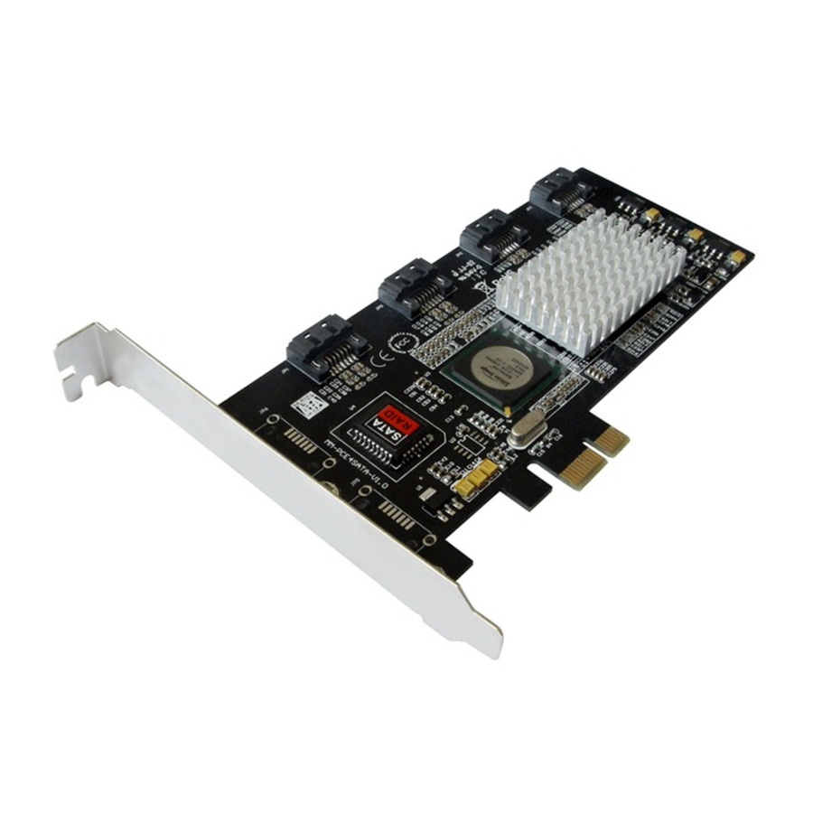
  • Page 11 Getting Help and Technical Assistance Before you call Using the documentation Getting help and information from the World Wide Web How to send Dynamic System Analysis data to IBM Creating a personalized support web page Software service and support Hardware service and support...
  • Page 12 Appendix B Notices Trademarks Important Notes Particulate contamination Documentation format Telecommunication regulatory statement Electronic emission notices Appendix C Glossary of Terms and Abbreviations Contents...
  • Page 13 SAS Plugs, SATA II Plugs, and SAS Backplane Receptacle Connector Connecting the ServeRAID M5014/M5015 Controller Internal Connectors to a Physical Drive Card Layout for the ServeRAID M5014/M5015 RAID Controllers ServeRAID M5000 Series Battery Assembly Installing the ServeRAID M5000 Series Battery Assembly on the ServeRAID M5014 Controller...
  • Page 14 Contents...
  • Page 15 Characteristics ServeRAID M5014 and ServeRAID M5015 SAS/SATA Controllers Specifications Array Performance Features Fault Tolerance Features Power Supply for the ServeRAID M5014/M5015 Controllers 3-8 Display BBU Information Display BBU Status Information Display BBU Capacity Information Display BBU Design Parameters Display Current BBU Properties...
  • Page 16 Contents...
  • Page 17: Overview

    Chapter 1 Overview This chapter provides a general overview of the ServeRAID M5014 SAS/SATA controller and the ServeRAID M5015 SAS/SATA controller, which have RAID control capabilities. It consists of the following sections: • Section 1.1, “Overview” • Section 1.2, “ServeRAID M5014/M5015 Controllers Descriptions and Limitations”...
  • Page 18 IBM offers a family of SAS controllers to address the needs for both internal solutions and external solutions. The ServeRAID M5000 Series Battery Assembly is pre-installed on the ServeRAID M5015 controller to provide battery-protected backup of cached memory.
  • Page 19: Serveraid M5014/M5015 Controllers Descriptions And Limitations

    SATA II device through an attached expander ServeRAID M5014/M5015 Controllers Descriptions and Limitations The ServeRAID M5014 and ServeRAID M5015 controllers are available with eight PHYs. The controllers have one LSISAS2108 ROC (RAID-on- chip) processor that controls eight internal SAS/SATA ports through two x4 SAS internal connectors.
  • Page 20: General Description

    General Description The ServeRAID M5014 and ServeRAID M5015 controllers bring 6.0 Gb/s Serial Attached SCSI and 3.0 Gb/s Serial ATA II performance to host adapter, workstation, and server designs. The controllers support internal storage devices, which allows you to use a system that supports enterprise-class SAS drives, and desktop-class SATA II drives.
  • Page 21: Configuration Scenarios

    failure. You can select the data backup method that best suits your needs. A hardware RAID assist exclusive-OR (XOR) engine speeds parity generation and checking and reduces system-access times. The controller supports the SAS protocol as described in the Serial Attached SCSI Standard, version 2.0.
  • Page 22: Example Of A Sas Direct-Connect Application

    Figure 1.1 shows a direct-connect configuration. The Inter-IC (I interface communicates with peripherals. The external memory bus provides a 32-bit memory bus, parity checking, and chip select signals for pipelined synchronous burst static random access memory (PSBRAM), nonvolatile static random access memory (NVSRAM), and Flash ROM.
  • Page 23: Number Of Physical Disks Supported

    Figure 1.2 Example of a ServeRAID Controller Configured with an LSISASx12 Expander PCI Express Interface Peripheral Flash ROM/ SAS RAID Controller NVSRAM/ C/UART LSISAS2108 72-bit DDR/DDR2 with ECC PCI Express to SAS ROC Interface SRAM SDRAM SRAM SRAM SAS/SATA LSISASx12 Drives LSISASx12 Expander...
  • Page 24: Benefits Of The Sas Interface

    SCSI. The ServeRAID M5014 and ServeRAID M5015 controllers leverage a common electrical and physical connection interface that is compatible with Serial ATA technology. The SAS protocols and SATA II protocols use a thin, 7-wire connector instead of the 68-wire SCSI cable or 26-wire ATA cable.
  • Page 25: Pci Express Architecture

    PCI Express is a local bus system designed to increase data transfers without slowing down the central processing unit (CPU). You can install your ServeRAID M5014 or ServeRAID M5015 PCI Express SAS/SATA controllers in PCI Express computer systems with a standard bracket type.
  • Page 26: Sas Features

    RAID system configuration information; the MegaRAID SAS firmware is stored in flash ROM for easy upgrade. 1.6.1 SAS Features The following list describes the SAS features of the ServeRAID M5014 and ServeRAID M5015 controllers: • Provides eight fully independent PHYs •...
  • Page 27: Sas Array Limitations

    Table 1.2 lists the array limitations for the ServeRAID M5014 and ServeRAID M5015 controllers. Table 1.2 ServeRAID M5014/M5015 SAS/SATA Controller Array...
  • Page 28: Sata Ii Features

    Allows multiple initiators to address a single target (in a fail-over configuration) through an expander 1.6.4 PCI Express Performance The following list describes the PCI Express performance features of the ServeRAID M5014 and ServeRAID M5015 controllers: • Provides a PCI Express interface that: – Supports a dedicated PCI Express bus –...
  • Page 29: Flexibility Features

    Supports the external SAS Sideband signal SFF-8485 (SGPIO) interface 1.6.6 Flexibility Features These features increase the flexibility of the ServeRAID M5014 and ServeRAID M5015 controllers: • Supports a Flash ROM interface, a nonvolatile static RAM (NVSRAM) interface, and a pipelined synchronous burst SRAM (PSBRAM) interface •...
  • Page 30: Drive Migration

    Note: If you move a drive that is being rebuilt, the rebuild operation will restart, not resume. Follow these steps to use drive roaming: Step 1. Turn off the power to the server and all physical disks, enclosures, and system components. Disconnect the power cords from the system.
  • Page 31 Step 9. Reconnect the power cords to the system. Step 10. Turn on the power to the system. The controller detects the RAID configuration from the configuration data on the drives. Benefits of the ServeRAID M5014 and ServeRAID M5015 Controllers 1-15...
  • Page 32: Hardware Specifications

    Hardware Specifications You can install your ServeRAID M5014 and ServeRAID M5015 controllers in a computer with a mainboard that has a PCI Express slot. Table 1.3 describes the hardware configuration features of the controllers. Table 1.3 ServeRAID M5014/M5015 SAS/SATA Controller...
  • Page 33: Technical Support

    Technical Support For information about the technical support available for this product, see Appendix A, “Getting Help and Technical Assistance”. Technical Support 1-17...
  • Page 34 1-18 Overview...
  • Page 35: Serveraid Controller Hardware Installation

    Section 2.5, “After Installing the Controller” Requirements The following items are required for installation: • A ServeRAID M5014 or ServeRAID M5015 SAS/SATA controller • A host system with an available PCI Express expansion slot • The ServeRAID-M Support CD containing the documentation •...
  • Page 36: Quick Installation

    Quick Installation The following steps are for quick installation of your controller. These steps are for experienced computer users/installers. Section 2.3, “Detailed Installation,” contains the steps for all others to follow. Step 1. Review all safety information provided with the server; then, turn off the power to the server and all of the attached devices, and unplug the server and the device power cords.
  • Page 37 Step 3. Review the Controller Connectors Refer to Chapter 3, “ServeRAID M5014/M5015 SAS/SATA Controller Characteristics” for a diagram of the ServeRAID M5014/M5015 controller with its connectors. Step 4.
  • Page 38: Serveraid M5014/M5015 Controllers Installation In A Pci Express Slot

    Refer to Section 2.4, “SAS Device Cables” for SAS cable information. Refer to Section 2.4.1, “Connecting the ServeRAID M5014 or ServeRAID M5015 SAS/SATA Controller to Physical Drives,” for details on connecting the controller to the physical disks and the expanders.
  • Page 39 The maximum cable length is six meters. You can connect one device per SAS PHY unless you use an expander. System throughput problems can occur if the SAS cables are not the correct type. To minimize the potential for problems: a.
  • Page 40: Sas Device Cables

    Device driver updates are made available periodically. To ensure that you have the current version of the driver, download the latest driver at http://www.ibm.com/support/. See the readme file that accompanies the driver for any updated information. For details on installing the driver, refer to the ServeRAID-M Device Driver Installation User’s Guide on the ServeRAID-M...
  • Page 41: Internal Sas Cable For Connection To Sas Physical Drives Or Sata Ii Physical Drives

    Figure 2.2 Internal SAS Cable for Connection to SAS Physical Drives or SATA II Physical Drives Physical Drive Connector Serial Signal Cables RAID Controller to HDD Breakout Cable 4-Lane Internal Connector SFF 8484 The following figure displays the SATA II device plug connector used to connect a controller with internal connectors to the host receptable connector on a backplane.
  • Page 42: Connecting The Serveraid M5014 Or Serveraid M5015

    SAS drives. 2.4.1 Connecting the ServeRAID M5014 or ServeRAID M5015 SAS/SATA Controller to Physical Drives This subsection provides step-by-step instructions for connecting your ServeRAID M5014 or ServeRAID M5015 controller to the SAS physical ServeRAID Controller Hardware Installation...
  • Page 43: Connecting The Serveraid M5014/M5015 Controller Internal Connectors To A Physical Drive

    If you have another physical drive, connect it to another plug on the internal cable. You can connect other devices if the cable has more connectors. Figure 2.5 Connecting the ServeRAID M5014/M5015 Controller Internal Connectors to a Physical Drive SAS Device Cables...
  • Page 44: After Installing The Controller

    After Installing the Controller After the you install the controller, you must configure it and install the operating system driver. The ServeRAID-M Software User’s Guide instructs you on the configuration options and how to set them on your controller. The ServeRAID-M Device Driver Installation User’s Guide provides detailed installation instructions for operating system drivers.
  • Page 45: Serveraid M5014/M5015 Sas/Sata Controller Characteristics

    Chapter 3 ServeRAID M5014/M5015 SAS/SATA Controller Characteristics This chapter describes the characteristics of the ServeRAID M5014 and ServeRAID M5015 SAS/SATA controllers. It consists of the following sections: • Section 3.1, “ServeRAID M5014/M5015 SAS/SATA Controller Descriptions” • Section 3.2, “Characteristics of the ServeRAID M5014/M5015 Controllers”...
  • Page 46: Board Layout And Connector Information

    The controller has eight internal SAS/SATA connectors. The following figure displays the connectors on the controller, while are described on Table 3.1. Figure 3.1 Card Layout for the ServeRAID M5014/M5015 RAID Controllers Table 3.1 ServeRAID M5014 and ServeRAID M5015 Controllers Connectors...
  • Page 47: Serveraid M5014 And Serveraid M5015 Controllers Connectors

    Table 3.1 ServeRAID M5014 and ServeRAID M5015 Controllers Connectors (Cont.) Connector Description Type Comments x4 SAS Ports 3–0 Mini SAS 4i Connects the cables from the connector controller to SAS drives or SATA II drives, or a SAS expander. x4 SAS Ports 7–4...
  • Page 48: Characteristics Of The Serveraid M5014/M5015 Controllers

    SAS domain. The controllers uses Fusion-MPT architecture, which allows for thinner drivers and better performance. Technical Specifications The design and implementation of the ServeRAID M5014 and ServeRAID M5015 SAS/SATA controllers minimize electromagnetic emissions, susceptibility to radio frequency energy, and the effects of electrostatic discharge.
  • Page 49: Controller Specifications

    In addition, the controller meets the requirements of CISPR Class B. The ServeRAID M5014 SAS/SATA controller, the ServeRAID M5015 SAS/SATA controller, and the ServeRAID M5000 Series Battery Assembly are CSA C22.2 No. 60950-1, UL 60950-1 First Edition listed Accessory, UL file number E257743.
  • Page 50: Array Performance Features

    Controllers Specifications (Cont.) Specification ServeRAID M5014/M5015 SAS/SATA Controllers Cache Configuration ServeRAID M5014 - Integrated 256 Mbyte 40-bit Double Data Rate II ECC 800 MHz SDRAM ServeRAID M5015 - Integrated 512 Mbyte 72-bit Double Data Rate II ECC 800 MHz SDRAM...
  • Page 51: Fault Tolerance

    3.3.3 Fault Tolerance Table 3.5 shows the fault tolerance features of the ServeRAID M5014 and ServeRAID M5015 SAS/SATA controllers. Table 3.5 Fault Tolerance Features Specification ServeRAID M5015 SAS/SATA Controllers Support for SMART Optional Battery Backup for ServeRAID M5000 Series Battery Assembly.
  • Page 52: Operating And Non-Operating Conditions

    3.3V ± - 9 percent (from PCI edge connector only). Table 3.6 lists the power supply for the controller for each of the three states at the different voltages. Table 3.6 Power Supply for the ServeRAID M5014/M5015 Controllers PCI Edge Connector State 1 State 2 State 3 3.3V supply...
  • Page 53: Safety Characteristics

    3.3.6 Safety Characteristics The ServeRAID M5014 and ServeRAID M5015 SAS/SATA controllers meet or exceed the requirements of UL flammability rating 94 V0. Each bare board is also marked with the supplier name or trademark, type, and UL flammability rating. The board is installed in a PCI Express bus slot, so all voltages are lower than the SELV 42.4 V limit.
  • Page 54 3-10 ServeRAID M5014/M5015 SAS/SATA Controller Characteristics...
  • Page 55: Intro To The Serveraid M5000 Series Battery Assembly

    The ServeRAID M5000 Series Battery Assembly has built-in functionality to charge the battery pack automatically and to communicate battery status information such as voltage, temperature, and current, to the host computer system. ServeRAID M5014/M5015 SAS/SATA Controller User’s Guide...
  • Page 56 The battery is a lithium ion battery. To avoid possible explosion, do not burn. Exchange only with the IBM-approved part. Recycle or discard the battery as instructed by local regulations. In the United States, IBM has a process for the collection of this battery. For information, call 1-800-426- 4333.
  • Page 57: Installing A Serveraid M5000 Series Battery Assembly

    Installing a ServeRAID M5000 Series Battery Assembly This chapter explains how to install a ServeRAID M5000 Series Battery Assembly on the ServeRAID M5014 controller. Note: The ServeRAID M5000 Series Battery Assembly is pre- installed on the ServeRAID M5015 controller. Attention: Electrostatic discharge can damage the battery assembly and the controller on which it is installed.
  • Page 58: Installing The Serverraid M5000 Series Battery Assembly On A Controller

    Installing the ServerRAID M5000 Series Battery Assembly on a Controller The ServeRAID M5000 Series Battery Assembly is compatible with systems that offer auxiliary power. Battery charging and recharging take place automatically. The battery assembly mounts directly to the controller using a small board-to-board connector (daughtercard). The following figure displays the top view and the bottom view of the card.
  • Page 59 The battery is a lithium ion battery. To avoid possible explosion, do not burn. Exchange only with the IBM-approved part. Recycle or discard the battery as instructed by local regulations. In the United States, IBM has a process for the collection of this battery. For information, call 1-800-426- 4333.
  • Page 60: Installing The Serveraid M5000 Series Battery Assembly On The Serveraid M5014 Controller

    . Figure 5.2 Installing the ServeRAID M5000 Series Battery Assembly on the ServeRAID M5014 Controller 4. Carefully press the battery assembly onto the controller, so that the two connectors are firmly joined. 5. Secure the battery assembly to the controller with the screws and the standoffs in the three screwholes.
  • Page 61: Installing The Serveraid M5014 Controller

    Figure 5.3 Installing the ServeRAID M5014 Controller 8. Attach the controller to the computer chassis with the bracket screw. 9. Attach the cables, as needed, to the connectors on the controller.
  • Page 62 Installing a ServeRAID M5000 Series Battery Assembly...
  • Page 63: Using The Serveraid M5000 Series Battery Assembly

    M5000 Series Battery Assembly This chapter explains how to monitor and maintain the ServeRAID M5000 Series Battery Assembly for your ServeRAID M5014 or ServeRAID M5015 SAS/SATA controllers. Most of the battery assembly functions, such as battery recharging, occur automatically. Click on the following links to view instructions on how to use the battery assembly: •...
  • Page 64: Monitoring The Battery Backup With The Megaraid Configuration Utilities

    Monitoring the Battery Backup with the MegaRAID Configuration Utilities This section describes the MegaRAID configuration utilities you can use to monitor the condition of the installed ServeRAID M5000 Series Battery Assembly and to change the automatic learn mode options. They include the WebBIOS Configuration Utility, MegaCLI, and MegaRAID Storage Manager.
  • Page 65: First Controller Properties Screen

    Figure 6.1 First Controller Properties Screen 4. Click Next to view the second Controller Properties screen. The second Controller Properties screen appears, as shown in the following figure. The Battery Backup field at the top left of the screen indicates whether the battery backup assembly is present. Figure 6.2 Second Controller Properties Screen Monitoring the Battery Backup with the MegaRAID Configuration Utilities...
  • Page 66: Battery Module Screen

    You can change the learn delay interval and the auto learn mode. Note: IBM recommends leaving the the learn delay interval and the auto learn mode at their default settings. Using the ServeRAID M5000 Series Battery Assembly...
  • Page 67: Setting The Learn Delay Interval

    6.1.1.1 Setting the Learn Delay Interval The learn delay interval is the length of the interval between automatic learning cycles. Perform the following steps to change the interval: 1. Open the drop-down menu in the Auto Learn Mode field. 2. Set the learn mode as Auto (the default). 3.
  • Page 68: Monitoring The Serveraid M5000 Series Battery Assembly With The Megacli Utility

    6.1.2 Monitoring the ServeRAID M5000 Series Battery Assembly with the MegaCLI Utility You can use the MegaCLI commands in this section to monitor the battery assembly and to select the settings for battery backup unit (BBU)-related options. 6.1.2.1 Display BBU Information Use the command in Table 6.1 to display complete information about the...
  • Page 69 Table 6.2 Display BBU Status Information Description Displays complete information about the BBU status, such as the temperature and voltage. The information displays in the following formats: BBU Status for Adapter: xx Battery Type: XXXXXX(string) Voltage: xx mV Current: xx mA Temperature: xx C°...
  • Page 70: Display Bbu Capacity

    6.1.2.3 Display BBU Capacity Use the command in Table 6.3 to display the BBU capacity for the selected controller(s). Table 6.3 Display BBU Capacity Information Convention MegaCli -AdpBbuCmd -GetBbuCapacityInfo –aN|-a0,1,2|-aALL Description Displays BBU capacity information. The information displays in the following format: BBU Capacity Info for Adapter: x Relative State of Charge: xx% Absolute State of Charge: xx%...
  • Page 71: Display Current Bbu Properties

    6.1.2.5 Display Current BBU Properties Use the command in Table 6.5 to display the current BBU properties for the selected controller(s). Table 6.5 Display Current BBU Properties Convention MegaCli -AdpBbuCmd -GetBbuProperties –aN|-a0,1,2|-aALL Description Displays current properties of the BBU. The information displays in the following formats: BBU Properties for Adapter: x Auto Learn Period: xxx Sec...
  • Page 72: Set Bbu Properties

    6.1.2.8 Set BBU Properties Use the command in Table 6.8 to set the BBU properties on the selected controller(s) after reading from the file. Table 6.8 Set BBU Properties Convention MegaCli -AdpBbuCmd -SetBbuProperties -f<fileName> -aN|-a0,1,2|-aALL Description Sets the BBU properties on the selected controller(s) after reading from the file. The information displays in the following formats: autoLearnPeriod = 1800Sec nextLearnTime = 12345678Sec Seconds past 1/1/2000...
  • Page 73: Battery Learn Cycle

    Figure 6.4 Battery Backup Unit Information The BBU properties include the following: • The number of times the BBU has been recharged (Cycle Count) • The full capacity of the BBU, plus the percentage of its current state of charge, and the estimated time until it will be depleted •...
  • Page 74: Setting The Learn Cycle Properties

    battery learn cycles, enable automatic learn cycles. To choose manual battery learn cycles, disable automatic learn cycles. If you enable automatic learn cyles, you can delay the start of the learn cycles for up to 168 hours (7 days). If you disable automatic learn cycles, you can start the learn cycles manually, and you can choose to receive a reminder to start a manual learn cycle.
  • Page 75: Starting A Learn Cycle Manually

    To avoid possible explosion, do not burn. Keep away from children. Exchange only with the IBM-approved part. Recycle or discard the battery as instructed by local regulations. In the United States, IBM has a process for the collection of this battery. For information, call 1-800-426- 4333.
  • Page 76: Resolving A Configuration Mismatch

    Resolving a Configuration Mismatch If the replacement controller has a previous configuration, this message displays during the power-on self-test (POST): Unresolved configuration mismatch between disk(s) and NVRAM on the adapter A configuration mismatch occurs when the configuration data in the NVRAM and the configuration data on the drives are different.
  • Page 77: Serveraid M5000 Series Battery Assembly Specifications

    Note: The ServeRAID M5000 Series Battery Assembly is not pre- installed on the ServeRAID M5014 controller but can be installed, if desired. See Section 5.1, “Installing the ServerRAID M5000 Series Battery Assembly on a Controller”...
  • Page 78: Battery Life And Data Retention Time

    30–90 days: 0–40° C > 90 days: 0–30° C Table 7.1 ServeRAID M5000 Series Battery Assembly Specifications ServeRAID M5000 Series Battery Assembly Fast Charge Rate 500 mAH Battery Pack 1 cell Mechanical 2.611” x 2.122” Battery Capacity 1350 mAH Charge Circuitry Card Memory Technology DDR2 SDRAM (1.8V) Battery Fast Charge Time...
  • Page 79: Reference Data Retention Times

    • Capacity of the battery pack and the battery load • Ambient temperature • Battery age and the number of discharge cycles • Number of DIMMs installed and the number of chips on the DIMMs • DRAM size Table 7.2 Reference Data Retention Times Data Retention Times - 48 hours for 512 Mbytes, using five 64 Mx16 parts DDR2...
  • Page 80: Serveraid M5000 Series Battery Assembly

    ServeRAID M5000 Series Battery Assembly Specifications...
  • Page 81: Installing A Serveraid M5000 Series Advanced Feature Key

    Perform the following steps to install the ServeRAID M5000 Series Advanced Feature Key directly to the ServeRAID M5015 SAS/SATA controller. 1. Turn off the computer and unplug the power cords from the rear of the power supply. ServeRAID M5014/M5015 SAS/SATA Controller User’s Guide...
  • Page 82: Installing The Serveraid M5000 Series Advanced Feature Key On The M5015 Serveraid Sas/Sata Controller

    2. Remove the cover from the computer according to the instructions in the system user’s manual so you can access the controller. Note: When handling static sensitive devices, take precautions to avoid damage from static electricity. 3. Ground yourself before you touch the controller or the Advanced Feature Key.
  • Page 83: Appendix A Getting Help And Technical Assistance

    If you need help , serv ice, or technical assistance o r just want more in formation about IBM produ cts, you will find a wide variety of sources available from IBM to assist you. Use this information to obtain ad ditional information about IBM and IBM products, determine what to do if you experience a problem with your IBM system or optional device, and determine whom to call for service, if it is necessary.
  • Page 84: Before You Call

    (unless it is cov ered by an additional maintenance contract). Your IBM service tech nician will request that yo u up grad e your software and firmware if the problem has a documented solution within a software upg rade.
  • Page 85: Using The Documentation

    A.2 Using the documentation Informatio n about your IBM s ystem and preinstalled software, if an y, or optional device is available in the documentation that comes with th e product. That documentation can includ e printed documents, on line d ocuments, readme files, and help files. See the troub leshooting information in your system documentation fo r instructions for using the diagn ostic programs.
  • Page 86: Creating A Personalized Support Web Page

    A.5 Creating a personalized support web page At http://www.ibm.com/support/mynotifications/, you can create a personalized support web p age b y identifying IBM products that are of interest to you. From this personalized page, you can subscribe to weekly email notifications about n ew technical d ocuments, search for information and downloads, and access various administrative services.
  • Page 87: Ibm Taiwan Product Service

    A.8 IBM Taiwan product service IBM Taiwan product service...
  • Page 88 Getting Help and Technical Assistance...
  • Page 89: Appendix B Notices

    Appendix B Notices ServeRAID M5014/M5015 SAS/SATA Controllers User’s Guide...
  • Page 90: Trademarks

    IBM, the IBM logo, and ibm.com are trademarks of International Business Machines Corp., registered in many jurisdictions worldwide. Other product and service names might be trademarks of IBM or other companies. A current list of IBM trademarks is available on the web at "Copyright and trademark information" at http://www.ibm.com/legal/copytrade.shtml Adobe and PostScript are either registered trademarks or trademarks of Adobe Systems Incorporated in the United States and/or other countries.
  • Page 91: Important Notes

    IBM makes n o representations or warranties with respect to non-IBM produ cts. Support (if any) for the non -IBM prod ucts is provid ed by the third party, not IBM. Some software might differ from its retail version (if av ailable) and might no t include user manuals or all program fun ctionality.
  • Page 92: Particulate Contamination

    If IBM determines that the levels of particulates or gases in your environment have caused damage to the device, IBM may condition provision of repair or replacement of devices or parts on implementation of appropriate remedial measures to mitigate such environmental contamin ation.
  • Page 93: Documentation Format

    In the request, be sure to include the pu blication part number and title. When you send information to IBM, you grant IBM a nonexclusive right to use or distribute the info rmation in any way it believes appropriate without incu rring any obligation to you.
  • Page 94 Notices...
  • Page 95 Electronic emission notices...
  • Page 96 Notices...
  • Page 97 914-499-1900 • Der verantwortliche Ansprechpartner des Herstellers in der EU ist: IBM Deutschland • Technical Regulations, Department M456 • IBM-Allee 1, 71137 Ehningen, Germany • Telephone: +49 7 032 15-2937 • Email: tjahn@de.ibm.com • Generelle Informa tionen: Das Gerät erfüllt die Schutzanforderungen nach EN 55024 und EN 5502 2 Klasse A.
  • Page 98 This is a Class A product based on the standard of the Voluntary Control Council for Interference (VCCI). If this equipment is used in a domestic environment, radio interference may occur, in which case the user may be required to take corrective actions. This is electromagnetic wave compatibility equipment for business (Type A).
  • Page 99: Appendix C Glossary Of Terms And Abbreviations

    A SAS device installed outside the computer cabinet. These devices are device connected using specific types of shielded cables. Fusion-MPT Fusion-MPT (Message Passing Technology) architecture consists of architecture several main elements: Fusion-MPT firmware, the Fibre Channel and ServeRAID M5014/M5015 SAS/SATA Controllers User’s Guide...
  • Page 100 SCSI hardware, and the operating system level drivers that support these architectures. Fusion-MPT architecture offers a single binary, operating system driver that supports both Fibre Channel and SCSI devices. host The computer system in which a storage controller is installed. It uses the storage controller to transfer information to and from devices attached to the SCSI bus.
  • Page 101 PCI Express goes beyond the PCI specification in that it is intended as a unifying I/O architecture for various systems: desktops, workstations, mobile, server, communications, and embedded devices. peripheral A piece of hardware (such as a video monitor, drive, printer, or CD-ROM) devices used with a computer and under the control of the computer.
  • Page 102 The ServeRAID M5120 SAS/SATA controller is a versatile controller that provides the backbone of both server and high-end workstation environments. Each port on the RAID controller supports SAS devices and/or SATA devices. SAS device Any device that conforms to the SAS standard and is attached to the SAS bus by a SAS cable.
  • Page 103 therefore, may have several stripes. The amount of space consumed by a stripe is the same on each disk included in the stripe. The portion of a stripe that resides on a single disk is a strip. Striping by itself does not provide data redundancy;...
  • Page 104 Glossary of Terms and Abbreviations...
  • Page 106 Part number: 81Y1027 ®...

This manual is also suitable for:

Serveraid m5015Serveraid m5014 sasServeraid m5014 sataServeraid m5015 sasServeraid m5015 sata

Table of Contents