Table of Contents
Advertisement
Quick Links
Advertisement
Table of Contents

Related Manuals for Alvarado Supervisor 4500


Summary of Contents for Alvarado Supervisor 4500
- Page 1 Supervisor 4500 (SU4500) Optical Turnstile with Bi-Directional Motorized Barriers Installation Instructions Alvarado Manufacturing Company, Inc. 12660 Colony Street, Chino, CA 91710 Phone: +1 (909) 591-8431 Fax: +1 (909) 628-1403 support@alvaradomfg.com www.alvaradomfg.com PUD4385R1-1...
-
Page 2: Table Of Contents
Supervisor 4500 Installation Instructions Contents Contents..................................2 Safety Precautions................................3 Safety Icons..................................3 Installation Tools................................4 Uncrating..................................4 Parts List..................................5 Introduction..................................7 Before You Begin................................9 Slab Requirements..............................9 Space Requirements..............................9 Electrical Requirements. -
Page 3: Safety Precautions
Supervisor 4500 Installation Instructions Safety Precautions The Supervisor 4500 may present a risk to persons and property if it is not installed and/or operated WARNING correctly. This manual must be read in its entirety and all safety and operations information must be followed. -
Page 4: Installation Tools
Supervisor 4500 Installation Instructions Installation Tools • Tape Measure • Hammer • #2 Phillips Head Screwdriver • Chalk Line • 9/16" Wrench • Precision Flat Head Screwdriver • Pencil • Torque Wrench (ft-lbs.) • Clear RTV Silicone • Hammer Drill •... -
Page 5: Parts List
This product is shipped with all installation hardware and components. If installing a single lane, refer to the Single Lane Parts List below. For additional lanes, refer to the Center Cabinet Parts List. Make sure that none of these parts are missing and/or damaged before beginning installation. If parts are missing and/or damaged, please contact Alvarado. Single Lane Parts List... - Page 6 Supervisor 4500 Installation Instructions Parts List (cont.) Center Cabinets are used to create additional lanes for multi-lane configurations. Each additional lane includes the parts below. Center Cabinet Parts List (Per Center Cabinet) Front Anchor Block (Qty 2) Center Cabinet Barriers...
-
Page 7: Introduction
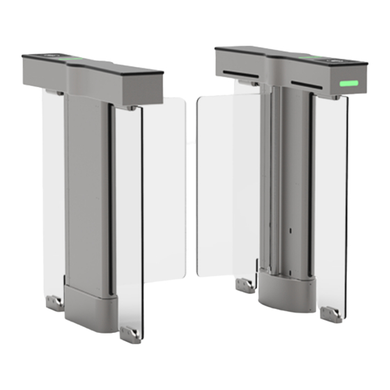
[Figure 1B]. Each cabinet has an unsecured and secured side. Alvarado follows what we call the “right-hand rule." User status lights and card readers are always installed on the right-hand side as you enter the turnstile. - Page 8 Alvarado’s TCP/IP control and monitoring software. (2) It allows easy implementation of SU4500 application software updates and enhancements. If the SU4500s are networked, updates can be installed over the network. (3) Alvarado has future plans to further develop the TCP/IP capabilities of the SU4500. The benefits of this future development can only be realized if the turnstiles are networked.
-
Page 9: Before You Begin
Supervisor 4500 Installation Instructions Before You Begin Use only skilled technicians for site preparation and installation of the turnstile using Alvarado’s instructions. Slab Requirements The following slab requirements must be taken into consideration when selecting the installation location: • A level solid concrete pad with a minimum thickness of 4" (102mm). -
Page 10: Electrical Requirements
Fuse 2.5A (slo-blo) located in the Main cabinet Drive Motor 24 VDC (brushless) Surge Protection Alvarado suggests the use of surge protection on the high-voltage power line to further protect electronics Page 10 For assistance: support@alvaradomfg.com +1 (909) 591-8431 PUD4385R1-1... -
Page 11: Conduit Requirements
Supervisor 4500 Installation Instructions Conduit Requirements NOTE Fig. 5 Fig. 5 SU4500 Conduit Lines SU4500 Conduit Lines The opening for the conduit in the center of each cabinet is 6.50” x 2.50” (165mm x 64mm). The three required conduits MUST fit in this area [Figure 5]. -
Page 12: Communication Requirements
NEVER connect signal lines containing voltage directly to the I/O control board. Network Communication A networked PC with Alvarado's TCP/IP control and monitoring software is required. Adhere to IEEE standards for network cabling requirements. Internal Card Reader Installation Requirements Card readers or other physical access devices may be installed under the top channel lid on either or both right-hand sides of the turnstile. -
Page 13: Pre-Installation Instructions
Supervisor 4500 Installation Instructions Pre-Installation Instructions NOTE It is assumed that the Pre-Installation Checklist steps are complete. Cabinet Panel Removal Fig. 6 Fig. 6 Removing Screws Removing Screws Using a Phillips screwdriver, remove the six (6) mounting screws that secure the cabinet panel to the Main cabinet [Figure 6]. -
Page 14: Installation Instructions
Supervisor 4500 Installation Instructions Installation Instructions Anchoring the Turnstile Remove the turnstile cabinets from the wooden skids. Using a Phillips screwdriver, remove the L-bracket attached to the bottom edge of the stationary panels. Discard the bracket. NOTE The Lane 1 Main cabinet is always the right-most cabinet in relation to the unsecured side. - Page 15 Supervisor 4500 Installation Instructions Anchoring the Turnstile (cont.) Fig. 8 Fig. 8 Marking Anchor Holes Marking Anchor Holes Using a pencil, mark each mounting hole location on the center black frame of the turnstile . There will be a total of three (3) mounting holes per frame.
- Page 16 Supervisor 4500 Installation Instructions Anchoring the Turnstile (cont.) Fig. 10 Fig. 10 Securing Rear Anchor Blocks 12. Place the two (2) Rear Anchor Blocks onto the floor, aligning the anchor holes. Repeat for Secondary cabinet. 13. Insert two (2) 3/8" x 2-1/2 Hex Head Cap Screws and flat washers into each of the Rear Anchor Blocks.
-
Page 17: Internal Card Reader Installation
Supervisor 4500 Installation Instructions Internal Card Reader Installation Card readers used in conjunction with the sites' access control system are not included with the SU4500. Most card readers do not require separate power inputs. In the event that your reader requires a separate power input – do not draw power from the SU4500 power supply. -
Page 18: Wiring Instructions
Supervisor 4500 Installation Instructions Wiring Instructions It is assumed the External DC Power Supply has been mounted and NOTE wired for Primary Power. Low-Voltage conduit should be run to the turnstiles according to the Conduit Requirements. Refer to Appendix A for... -
Page 19: Led Light Connection From Secondary Cabinet
Supervisor 4500 Installation Instructions LED Light Connection from Secondary Cabinet The Secondary cabinet will contain a bundle of RJ45 cable located at the bottom of the black frame of the cabinet. This cable must be pulled along with the crossover cable and connect to the Main cabinet, if a single lane; or the last Center cabinet, if a multi-lane set. -
Page 20: I/O Control Board
Supervisor 4500 Installation Instructions I/O Control Board Signal Inputs and Outputs Main Cabinet Main Cabinet To / From Access Control System Fig. 15 Fig. 15 Inputs Signal inputs from outside systems are wired into the SU4500’s I/O control board. There are two types of input signals, momentary dry contacts (MDC) and sustained dry contacts (SDC). -
Page 21: I/O Control Board Terminal Descriptions
Supervisor 4500 Installation Instructions I/O Control Board Terminal Descriptions J2 Output Contacts J1 Input Contacts Pin # Function Contact Function & Behavior Pin # Function Contact Function & Behavior Name Description Type Description Name Description Type Description GNDX Ground Common output signal Ground Common input signal ground. -
Page 22: Configuring Passage Modes
Supervisor 4500 Installation Instructions Configuring Passage Modes The SU4500 provides bi-directional access control in conjunction with a facility access control system. For bi-directional applications, the entry and exit directions can be individually configured to different passage modes to suit facility requirements. For example, a turnstile can be configured for Controlled Passage mode in the entry direction, and No Passage mode in the exit direction. - Page 23 Supervisor 4500 Installation Instructions Setting No Passage Mode (I/O Control Board) Fig. 17 Fig. 17 Entry Direction Locate the ENTCLS and GND terminals. Use a wire jumper to connect the ENTCLS and GND terminals [Figure 17]. Entry Direction Exit Direction Locate the EXTCLS and GND terminals.
-
Page 24: Ethernet Communication (Optional)
Supervisor 4500 Installation Instructions Ethernet Communication (Optional) Fig. 19 Fig. 19 Enternet Cable Location Enternet Cable Location NOTE It is assumed that Ethernet cabling has been run to the turnstile via conduit and pulled through the conduit opening in Step 17 of the Anchoring the Turnstile section. - Page 25 Supervisor 4500 Installation Instructions Barrier Installation (cont.) Fig. 21 Fig. 21 Tightening Mounting Screws Tightening Mounting Screws Position the clamp bar on the barrier. Insert and tighten the mounting screws and clamp bar to 44 in-lbs. Test to make sure the barrier does not wiggle [Figure 21].
-
Page 26: Post-Installation Functions Check
Supervisor 4500 Installation Instructions Post-Installation Functions Check Alvarado turnstiles are thoroughly inspected and tested for proper performance prior to being shipped. Perform the following function checks to verify the turnstiles have been installed properly and are fully operational. If any problems are encountered during the functions check, refer to the Troubleshooting section on pg.33. - Page 27 Supervisor 4500 Installation Instructions Testing Turnstile Functionality Perform the following turnstile functionality tests to validate basic turnstile operation. Tests are provided for Controlled Passage, No Passage, and Free Passage modes. The following is assumed (Controlled Passage mode tests only): •...
- Page 28 Supervisor 4500 Installation Instructions Testing Turnstile Functionality (cont.) NO PASSAGE MODE Enter the turnstile. • Open / Closed Status Light is red. No Passage No Passage Entry / Exit Entry / Exit • No alarms sound when standing in the turnstile.
- Page 29 Ethernet Adapter Extension Extension NOTE 192.168.0.100 is the default IP address configured by Alvarado. If the turnstile has been assigned a different network IP address, ping that IP address instead. Contact your system administrator for network information. A successful ping will result in the message shown in [Figure 25]: Fig.
-
Page 30: Finish The Installation
Supervisor 4500 Installation Instructions Finish the Installation Cabinet Lid Installation Lower the lid onto the cabinet housing [Figure 26]. WARNING Do not force the lid into place. Doing so may damage the lid. Secure lid in place using a Phillips screwdriver and eight (8) lid screws [Figure 26]. -
Page 31: Cabinet Panel Installation
Supervisor 4500 Installation Instructions Cabinet Panel Installation Fig. 27 Fig. 27 Cabinet Panel Installation Cabinet Panel Installation Orient the cabinet panel so the sensor windows are at the bottom and gently slide the cabinet panel into position. Using a Phillips screwdriver, insert and tighten the six (6) mounting screws that secure the cabinet panel to the cabinet [Figure 27]. -
Page 32: Post-Installation Checklist
Acrylic - Wipe down acrylic barriers using a soft cloth and cleaner suitable for acrylic surfaces. We recommend Brillianize and Novus #1 acrylic cleaners. Stainless Steel – Wipe down stainless steel with a damp cloth or use Alvarado's recommended commercial products (see SU4500 User Guide). -
Page 33: Troubleshooting
Locate the motor controller board fuses [Figure 30]. Using a multimeter, check the boot. board fuse is 5VDC 3A and 12VDC 2A fuses for continuity. If a fuse is blown, contact Alvarado for a blown. replacement. NOTES: If a user status display or open / closed status light is out, this may indicate the 5VDC 3A fuse is blown. -
Page 34: Appendix A - External Dc Power Supply Installation
One power supply is required per lane. Each power supply enclosure can house up to three power supplies. The power supplies are pre-installed at Alvarado prior to shipping. Make sure to locate all required components, and verify the correct number of power supplies are present prior to beginning installation. - Page 35 Supervisor 4500 Installation Instructions Connect Primary Power to Enclosure(s) Fig. A3 Fig. A3 Primary Power Terminal Block Primary Power Terminal Block NOTE Primary power wiring and connectors are not supplied by Conduit Alvarado. Hole The primary wiring lines for 110VAC and 220VAC consist of the...
- Page 36 If you do not require all twelve connectors, only use what is needed. Due to the differences of each installation scenario, 24VDC wire is not supplied by Alvarado. See the recommendations below for selecting the best wire for your installation.
- Page 37 Supervisor 4500 Installation Instructions Option: Power Buffer - Connect from Enclosure to Turnstile The Remote Power Supply option can also include a Power Buffer, which ensures the barriers open towards the exit direction upon power loss. The Power Buffer for the Remote Power Supply requires one additional connection to be made from the enclosure relay(s) to each respective turnstile I/O Board;...
- Page 38 Supervisor 4500 Installation Instructions External DC Power Supply Connection Diagram Connection Diagram Connection Diagram Fig. A6 Fig. A6 TO CIRCUIT BREAKER 110VAC / 220VAC INPUT POWER SUPPLY ENCLOSURE 24VDC OUTPUT NOTE If the power buffer option is not included, up to 3 lanes are supported per each remote enclosure.
- Page 39 Supervisor 4500 Installation Instructions Power Supply Enclosure Dimensions Fig. A7 Fig. A7 Dimensions Dimensions 15.80[401.4] 9.50[241.3] 6.23[158.1] 0.5 [12.7] 110 / 220VAC 24VDC CONDUIT HOLE CONDUIT HOLES For assistance: support@alvaradomfg.com +1 (909) 591-8431 Page 39 PUD4385R1-1...
-
Page 40: Appendix B - Setting The Home Position
Supervisor 4500 Installation Instructions Appendix B - Setting the Home Position Fig. B1 Fig. B1 Locate the motor controller board in the Main or center Main Cabinet - Motor Controller Board Main Cabinet - Motor Controller Board cabinet [Figure B1 or B2] respectively. The (D2) LED will be blinking indicating normal operation mode. -
Page 41: Appendix C - 36" Single Lane - Plan, Elevation, & Footprint Drawing
Supervisor 4500 Installation Instructions Appendix C - 36" Single Lane - Plan, Elevation, & Footprint Drawing Plan View 50.3 [1278] [431] 38 [965] 36 [914] Elevation View 41.0 [1041] 6.0 [152] Footprint For assistance: support@alvaradomfg.com +1 (909) 591-8431 Page 41... -
Page 42: Appendix D - Multi-Lane Conduit Requirements
Supervisor 4500 Installation Instructions Appendix D - Multi-Lane Conduit Requirements Two - Lane Configuration Three - Lane Configuration Symbology Description Conduit Size Low-Voltage - 1/2” 24VDC Access Control / 3/4” Ethernet Access 3/4” Control Crossover 1.5” Cable The opening for the conduit in the center of each cabinet is 6.50”... -
Page 43: Appendix E - Crossover Cable Connection Diagrams
Supervisor 4500 Installation Instructions Appendix E - Crossover Cable Connection Diagrams One-Lane Configuration Secondary Secondary Main Main Secondary Main Cabinet Cabinet Two-Lane Configuration LANE 2 LANE 1 Main Main Secondary Secondary Main Main Secondary Secondary Secondary Center Cabinet Main Cabinet... -
Page 44: Appendix F - Single Lane Platform Dimensions - 28" & 36" Passages
Supervisor 4500 Installation Instructions Appendix F - Single Lane Platform Dimensions - 28" & 36" Passages Fig. F1 Fig. F1 28" Baseplate Dimensions 28" Baseplate Dimensions 46.8 [ 1189 ] [MINIMUM REQUIRED SPACE] 42.6 [ 1087 ] [OVERALL] 48.5 [ 1231 ] Fig. -
Page 45: Revision History
Supervisor 4500 Installation Instructions Revision History Revision Date Author Description 6/7/2019 C. Maynez Initial document creation. 6/30/2020 C. Maynez Updated: Installation instructions, conduit size callout, corrected page callouts, Terminology. Added: Appendix A, & Appendix F. For assistance: support@alvaradomfg.com +1 (909) 591-8431... - Page 46 Supervisor 4500 Installation Instructions This page intentionally left blank. Page 46 Installation Instructions support@alvaradomfg.com +1 (909) 591-8431 www.alvaradomfg.com...
Need help?
Do you have a question about the Supervisor 4500 and is the answer not in the manual?
Questions and answers