Table of Contents
Advertisement
Quick Links
Advertisement
Table of Contents

Related Manuals for Alvarado SUPERVISOR 5000


Summary of Contents for Alvarado SUPERVISOR 5000
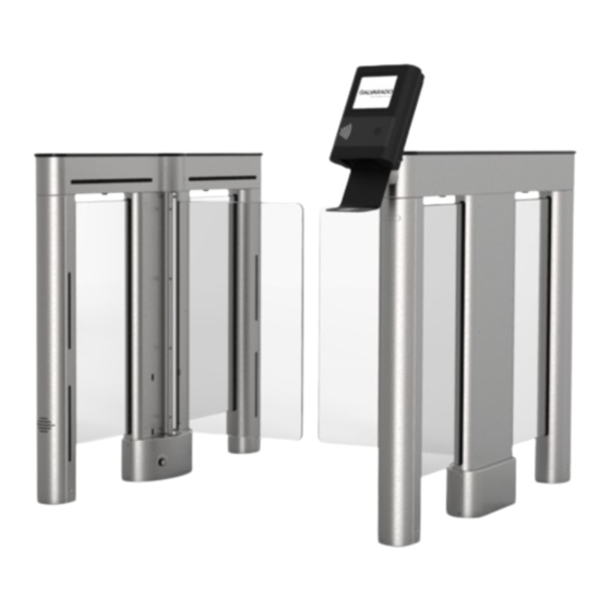
- Page 1 SUPERVISOR 5000 with Integrated IntraQ Admission Device Installation Instructions Alvarado Manufacturing Company, Inc. 12660 Colony Street, Chino, CA 91710 Phone: +1 (909) 591-8431 Fax: +1 (909) 628-1403 support@alvaradomfg.com www.alvaradomfg.com PUD4472R2-0...
-
Page 2: Table Of Contents
IntraQ-SU5000 Installation Instructions Contents Contents..................................2 ETL Certification................................2 Safety Precautions................................3 Safety Icons..................................3 Installation Tools................................4 Uncrating..................................4 Parts List..................................4 Introduction..................................6 SU5000 Cabinets..............................6 Before You Begin................................8 Slab Requirements. -
Page 3: Safety Precautions
IntraQ-SU5000 Installation Instructions Safety Precautions The Supervisor 5000 may present a risk to persons and property if it is not installed and/or operated WARNING correctly. This manual must be read in its entirety and all safety and operations information must be followed. -
Page 4: Installation Tools
This product is shipped with all installation hardware and components. If installing a two-lane set, refer to the Two-Lane Set Parts List below. For single-lane set, refer to the Single-Lane Set Parts List. Make sure that none of these parts are missing and/or damaged before beginning installation. If parts are missing and/or damaged, please contact Alvarado. Two-Lane Set Parts List... - Page 5 IntraQ-SU5000 Installation Instructions Parts List (cont.) Two-Lane Set Parts List (Cont.) Hardware: • Barrier Clamp Bars (Qty 4) • Barrier Clamp Bar Screws (Qty 16) Concrete Anchor Package: • ⅜" x 2" Concrete Anchors (Qty 21) • ⅜" x 2½" Hex Head Cap Screws (Qty 21) •...
-
Page 6: Introduction
IntraQ-SU5000 Installation Instructions Introduction This manual covers the physical installation process for IntraQ-SU5000 Optical Turnstiles. A separate IntraQ-SU5000 User Guide (PUD4454) provides operating instructions and additional information such as configuring turnstiles for bi-directional passage applications and monitoring outputs. It is highly recommended that both this manual and the IntraQ-SU5000 User Guide (PUD4454) be read in their entirety prior to beginning installation. - Page 7 IntraQ-SU5000 Installation Instructions Barrier Height 69.0 (1752) SU5000 barriers come in low (35"), mid (46") and full (69") heights [Fig. 3]. Fig. 3 Barrier Heights Barrier Heights 46.0 (1168) 35.0 (889) 6.0 (152) 6.0 (152) 6.0 (152) Low Height Mid Height Full Height Barrier Barrier...
-
Page 8: Before You Begin
IntraQ-SU5000 Installation Instructions Before You Begin Use only skilled technicians for site preparation and installation of the turnstile using Alvarado’s instructions. Slab Requirements The following slab requirements must be taken into consideration when selecting the installation location: • A level solid concrete pad with a minimum thickness of 4" (102mm). -
Page 9: Conduit Requirements
Drive Motor 24 VDC (brushless) Surge Protection Alvarado suggests the use of surge protection on the high-voltage power line to further protect electronics Environmental Requirements • DO NOT install the product outdoors. This product is intended for indoor use only. -
Page 10: Communication Requirements
Communication Requirements The device must maintain an active network connection to the validation system to properly process scanned media. A networked PC with Alvarado's GateUtility software is also recommended to allow for easy device configuration and file updates. User Training All personnel that will be involved with operating the IntraQ-SU5000 should be trained in the proper method of operation. -
Page 11: Pre-Installation Instructions
IntraQ-SU5000 Installation Instructions Pre-Installation Instructions NOTE It is assumed that the Pre-Installation Checklist steps have been completed prior to beginning the installation. Cabinet Panel Removal Using a Phillips screwdriver, remove the six (6) mounting screws that secure the cabinet panel to the main cabinet Fig. -
Page 12: Baseplate Installation (Optional)
IntraQ-SU5000 Installation Instructions Baseplate Installation (Optional) NOTE Refer to "Appendix C - 28" & 36" Baseplate Dimensions" on page 32 for baseplate dimensions. The baseplate enables installation of the SU5000 turnstile on a solid foundation without the need to drill holes into the concrete. The baseplate also provides concealed conduit channels for wiring primary power, crossover communication, and access control. -
Page 13: Pre-Installation Instructions
IntraQ-SU5000 Installation Instructions Pre-Installation Instructions Anchoring the Turnstile NOTE The lane 1 main cabinet is always the right-most cabinet when viewed from the unsecured side. Place the main cabinet and the secondary cabinet in the determined location [see "Space Requirements" on page 8]. All cabinets must be level and square to each other. - Page 14 IntraQ-SU5000 Installation Instructions Anchoring the Turnstile (cont.) Fig. 12 Removing End Legs Removing End Legs Remove cabinet end legs with a Phillips screwdriver and 3/32" hex key [Fig. 12]. LOWER END Remove the card reader mounting bracket and set aside. Use a pencil and mark each mounting hole location [Fig.
-
Page 15: Intraq Head Installation
IntraQ-SU5000 Installation Instructions IntraQ Head Installation Fig. 15 Cable Routing Cable Routing Route an Ethernet cable from the base of the cabinet to the Ethernet connector in the top channel [Fig. 15]. Ethernet Connector Access Hole Exit Hole Fig. 16 IntraQ Case Screws IntraQ Case Screws Use a Phillips-head screwdriver to remove the four screws securing... -
Page 16: Wiring Instructions
IntraQ-SU5000 Installation Instructions Wiring Instructions 110VAC NOTE FOR EXTERNAL DC POWER SUPPLY INSTALLATION Fig. 18 INSTRUCTIONS, REFER TO "Appendix D - External DC Power Supply Installation (Optional)" on page 33. Primary Power Power Terminal Block NOTE 110VAC and 220VAC primary power must be hard wired in place. -
Page 17: I/O Control Board
IntraQ-SU5000 Installation Instructions I/O Control Board Signal Inputs and Outputs To / From Access Control System The I/O board is wired at the factory prior to shipment. Fig. 21 Main Cabinet Main Cabinet When uncrated, the cables from the I/O board are routed up to the IntraQ mounting plate on master cabinets. - Page 18 IntraQ-SU5000 Installation Instructions I/O Control Board (13-0328 Rev. G) Terminal Descriptions J1 Input Contacts Pin # Function Contact Function & Behavior Name Description Type Description Ground Common input signal ground. ENTPAS Free Sets the turnstile to Free Passage Passage mode in the entry Entry direction.
-
Page 19: Configuring Free-Pass Exit
IntraQ-SU5000 Installation Instructions Configuring Free-Pass Exit The SU5000 can be configured to allow patrons to freely exit through the turnstile without having to scan a ticket or other scan media first. Follow the instructions below to configure the SU5000 to allow free-pass exits. Entry Direction Fig. -
Page 20: Ethernet Communication (Optional)
IntraQ-SU5000 Installation Instructions Ethernet Communication (Optional) Fig. 24 I/O Control Board I/O Control Board NOTE It is assumed that Ethernet cabling has been run to the turnstile via conduit and pulled through the conduit opening in Step 6 of the Anchoring the Turnstile section. Locate the Ethernet extension cable tucked in the base of the main/center cabinet [Fig. - Page 21 IntraQ-SU5000 Installation Instructions Barrier Installation (cont.) Tightening Mounting Tightening Mounting Position the clamp bar on the barrier. Insert and tighten the Fig. 26 Screws Screws mounting screws and clamp bar to 44 in-lbs. Test to make sure the barrier does not wiggle [Fig. 26]. Clamp Bar Fig.
-
Page 22: Post-Installation Functions Check
Post-Installation Functions Check Alvarado turnstiles are thoroughly inspected and tested for proper performance prior to being shipped. Perform the following function checks to verify the turnstiles have been installed properly and are fully operational. If any problems are encountered during the functions check, refer to "Troubleshooting"... - Page 23 IntraQ-SU5000 Installation Instructions Testing Turnstile Functionality Perform the following turnstile functionality tests to validate basic turnstile operation. Tests are provided for Controlled Passage, Free Passage, and No Passage modes. The following is assumed (Controlled Passage mode tests only): • The access control system is operational and all access control wiring to the turnstile is connected. •...
- Page 24 IntraQ-SU5000 Installation Instructions Testing Turnstile Functionality (cont.) TEST PROCEDURE TURNSTILE RESPONSE Unauthorized Exit Enter the turnstile without authorization. • Unauthorized Entry / Exit alarm sounds. Secured Side Secured Side • Dynamic side panels flash red. • Barriers remain closed. Unsecured Unsecured Side Side...
- Page 25 Adapter Extension Extension 192.168.0.100 is the default IP address configured by Alvarado. If the IntraQ has been assigned a different NOTE network IP address, ping that IP address instead. Contact your system administrator for network information. A successful ping will result in the message shown in [Fig. 30]: Fig.
-
Page 26: Finish The Installation
IntraQ-SU5000 Installation Instructions Finish the Installation Cabinet Lid Installation Due to limited access, use the 4mm Allen 'stubby' wrench provided. (The wrench is taped to the underside of NOTE all end cabinet lids.) Lower the lid onto the cabinet housing [Fig. 31]. WARNING Do not force the lid into place. -
Page 27: Cabinet Panel Installation
IntraQ-SU5000 Installation Instructions Cabinet Panel Installation Orient the cabinet panel so the sensor windows are Fig. 32 Cabinet Panel Installation Cabinet Panel Installation at the bottom and gently slide the cabinet panel into position. Using a Phillips screwdriver, insert and tighten the six (6) mounting screws that secure the cabinet panel to the cabinet [Fig. -
Page 28: Post-Installation Checklist
Acrylic - Wipe down acrylic barriers using a soft cloth and cleaner suitable for acrylic surfaces. We recommend Brillianize and Novus #1 acrylic cleaners. Stainless Steel – Wipe down stainless steel with a damp cloth or use Alvarado's recommended commercial products (see SU5000 User Guide - PUD3668). -
Page 29: Troubleshooting
Locate the motor controller board fuses [Fig. 35]. Using a multimeter, check the boot. board fuse is 5VDC 3A and 12VDC 2A fuses for continuity. If a fuse is blown, contact Alvarado for a blown. replacement. NOTES: If a user status display or open / closed status light is out, this may indicate the 5VDC 3A fuse is blown. -
Page 30: Appendix A - Setting The Home Position
IntraQ-SU5000 Installation Instructions Appendix A - Setting the Home Position Locate the motor controller board in the center or main cabinet Fig. 37 Main Cabinet - Motor Controller Board Main Cabinet - Motor Controller Board [Fig. 36 & Fig. 37] respectively. The (D2) LED will be blinking indicating normal operation mode. -
Page 31: Appendix B - 36" Single Lane - Plan, Elevation & Footprint Drawing
IntraQ-SU5000 Installation Instructions Appendix B - 36" Single Lane - Plan, Elevation & Footprint Drawing Plan View Elevation View 68.9 (1749) Minimum Req. Space 43.1 (1094) 47.1 (1196) 45.9 (1165) 2.0 (51) 17.0 (432) 52.4 (1330) 34.8 (884) 60.8 36.0 (914) (1544) 41.0 (1041) -
Page 32: Appendix C - 28" & 36" Baseplate Dimensions
IntraQ-SU5000 Installation Instructions Appendix C - 28" & 36" Baseplate Dimensions Fig. 39 28" Baseplate Dimensions 28" Baseplate Dimensions 52.5 (1333.5) 40.8 (1036.5) Fig. 40 36" Baseplate Dimensions 36" Baseplate Dimensions 52.5 (1333.5) 48.8 (1239.7) Page 32 support@alvaradomfg.com +1 (909) 591-8431 www.alvaradomfg.com Installation Instructions... -
Page 33: Appendix D - External Dc Power Supply Installation (Optional)
One power supply is required per lane. Each power supply enclosure can house up to three power supplies. The power supplies are pre- installed at Alvarado prior to shipping. Make sure to locate all required components, and verify the correct number of power supplies are present prior to beginning installation. - Page 34 Connect Primary Power to Enclosure(s) Fig. 43 Primary Power Terminal Block Primary Power Terminal Block Primary power wiring and connectors are not NOTE supplied by Alvarado. Conduit The primary wiring lines for 110VAC and 220VAC consist of the Hole following: Terminal...
- Page 35 IntraQ-SU5000 Installation Instructions Connect Low-Voltage 24VDC from Enclosure to Turnstile(s) Twelve (12) ring connectors are supplied by Alvarado for connecting low-voltage 24VDC power to the turnstiles. If you do not require all twelve connectors, only use what is needed. Due to the differences of each installation scenario, 24VDC wire is not supplied by Alvarado. See the recommendations below for selecting the best wire for your installation.
- Page 36 IntraQ-SU5000 Installation Instructions Option: Power Buffer - Connect from Enclosure to Turnstile The Remote Power Supply option can also include a Power Buffer, which ensures the barriers open towards the exit direction upon power loss. The Power Buffer for the Remote Power Supply requires one additional connection to be made from the enclosure relay(s) to each respective turnstile I/O Board;...
- Page 37 IntraQ-SU5000 Installation Instructions External DC Power Supply Connection Diagram Fig. 48 Connection Diagram Connection Diagram TO CIRCUIT BREAKER 110VAC / 220VAC INPUT POWER SUPPLY ENCLOSURE 24VDC OUTPUT LANE 3 LANE 2 LANE 1 When the power buffer option is not included, up to 3 lanes are supported per each remote enclosure. If power buffer NOTE option is included, only 2 lanes are supported per remote enclosure.
- Page 38 IntraQ-SU5000 Installation Instructions Power Supply Enclosure Dimensions Fig. 49 Dimensions Dimensions Front 15.80[401.4] 6.08[154.3] 0.5 [12.7] 110 / 220VAC CONDUIT HOLE 24VDC 0.15[3.8] CONDUIT HOLES 9.50[241.3] Page 38 support@alvaradomfg.com +1 (909) 591-8431 www.alvaradomfg.com Installation Instructions...
-
Page 39: Appendix E - Multi-Lane Conduit Requirements
IntraQ-SU5000 Installation Instructions Appendix E - Multi-Lane Conduit Requirements Two-Lane Configuration LANE 2 LANE 1 Secondary Cabinet Center Cabinet Main Cabinet Three-Lane Configuration LANE 3 LANE 2 LANE 1 Secondary Cabinet Center Cabinet Center Cabinet Main Cabinet Symbology Description Conduit Size Primary 3/4”... -
Page 40: Appendix F - Crossover Cable Connection Diagrams
IntraQ-SU5000 Installation Instructions Appendix F - Crossover Cable Connection Diagrams One-Lane Configuration SECONDARY SECONDARY Main Main Main Cabinet Secondary Cabinet Two-Lane Configuration LANE 2 LANE 1 SECONDARY SECONDARY MAIN MAIN SECONDARY SECONDARY MAIN MAIN Secondary Cabinet Center Cabinet Main Cabinet Three-Lane Configuration LANE 3 LANE 2... -
Page 41: Revision History
IntraQ-SU5000 Installation Instructions Revision History Revision Date Author Description 9/2/2020 D Bohannon Original document 8/4/2021 D Bohannon Updated conduit measurements. Installation Instructions support@alvaradomfg.com +1 (909) 591-8431 www.alvaradomfg.com Page 41... - Page 42 12660 Colony Street, Chino, CA 91710 Telephone: (909) 591-8431 Fax: (909) 628-1403 support@alvaradomfg.com www.alvaradomfg.com © 2016 Alvarado Manufacturing Company, Inc. This work may not be reproduced, published or redistributed, in whole or in part, without the express prior written permission of Alvarado.
Need help?
Do you have a question about the SUPERVISOR 5000 and is the answer not in the manual?
Questions and answers