
Related Manuals for Manitou TMM 20 S1-E3


Summary of Contents for Manitou TMM 20 S1-E3
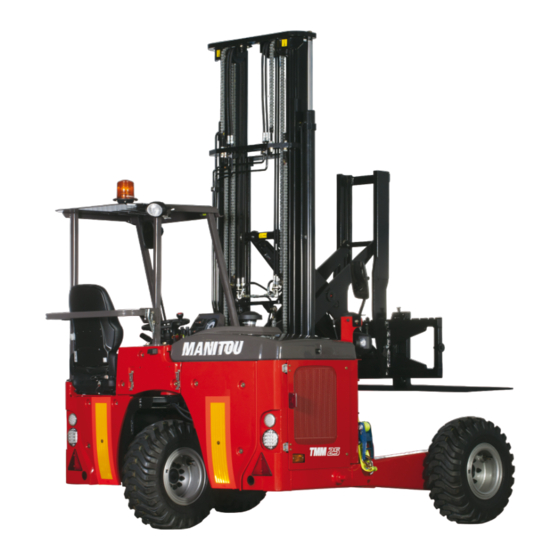
- Page 1 MANITOU BF BP 10249 44158 ANCENIS CEDEX - FRANCE TEL: + 33 (0)2 40 09 10 11 YOUR DEALER 647436 EN (03/02/2014) TMM 20 S1-E3 TMM 25 S1-E3 TMM 20 4W S1-E3 TMM 25 4W S1-E3 OPERATOR’S MANUAL (ORIGINAL INSTRUCTIONS)
- Page 3 - Descriptions and figures are non binding. - MANITOU reserves the right to change its models and their equipment without being required to update this manual. - The MANITOU network, consisting exclusively of qualified professionals, is at your disposal to answer all your questions.
- Page 4 1 - OPERATING AND SAFETY INSTRUCTIONS 2 - DESCRIPTION 3 - MAINTENANCE...
-
Page 5: Operating And Safety Instructions
1 - O P E R A T I N G A N D S A F E T Y INSTRUCTIONS... -
Page 6: Table Of Contents
TABLE OF CONTENTS 1 - OPERATING AND SAFETY INSTRUCTIONS INSTRUCTIONS TO THE COMPANY MANAGER THE SITE THE OPERATOR THE LIFT TRUCK A - THE TRUCK'S SUITABILITY FOR THE JOB ..........1-4 B - ADAPTATION OF THE LIFT TRUCK TO STANDARD ENVIRONMENTAL CONDITIONS . - Page 7 IF THE LIFT TRUCK IS NOT TO BE USED FOR A LONG TIME 1-20 INTRODUCTION 1-20 PREPARING THE LIFT TRUCK 1-20 PROTECTING THE ENGINE 1-20 PROTECTING THE LIFT TRUCK 1-20 BRINGING THE LIFT TRUCK BACK INTO SERVICE 1-21 LIFT TRUCK DISPOSAL 1-22 RECYCLING OF MATERIALS 1-22...
-
Page 8: Instructions To The Company Manager
A - THE TRUCK'S SUITABILITY FOR THE JOB - MANITOU has ensured that this lift truck is suitable for use under the standard operating conditions defined in this operator's manual, with a STATIC test coefficient OF 1.33 and a DYNAMIC test coefficient OF 1, as specified in standard EN 1726-1 for mast trucks. -
Page 9: C - Modification Of The Lift Truck
- The following are some tips for minimizing these vibration doses: • Select the most suitable lift truck and attachment for the intended use. (according to lift truck model) • Adapt the seat adjustment to the operator's weight and maintain it in good condition, as well as the cab suspension. -
Page 10: Instructions To The Operator
Failure to respect the safety and operating instructions, or instructions for repairing or servicing your lift truck, may lead to serious, even fatal accident. In order to reduce or avoid any danger with a MANITOU-approved attachment, follow the instructions of paragraph: 4 - ADAPTABLE ATTACHMENTS IN OPTION ON THE RANGE: INTRODUCTION. -
Page 11: F - Rear Of Vehicle Attachment System
The use of any lift truck attachment system at the rear of the transport vehicle other than those recommended by MANITOU must be approved by MANITOU. The use of any system for attaching the lift truck to the rear of the transport vehicle requires a special procedure. -
Page 12: Operating Instructions Unladen And Laden
OPERATING INSTRUCTIONS UNLADEN AND LADEN A - BEFORE STARTING THE LIFT TRUCK - Perform the daily service (see: 3 - MAINTENANCE: A - DAILY OR EVERY 10 HOURS SERVICE). - Make sure the lights, indicators and windscreen wipers are working properly. - Make sure the rear view mirrors are in good condition, clean and properly adjusted. -
Page 13: D - Visibility
- Never stack loads on uneven ground, they may tip over. - The load or the attachment must not be left just above a structure for long periods at a time because of the descending mast. In such a case, a constant watch must be kept and the height of the forks or the attachment readjusted if necessary. - When working near aerial lines, ensure that the safety distance is sufficient between the working area of the lift truck and the aerial line. -
Page 14: F - Driving The Lift Truck
F - DRIVING THE LIFT TRUCK SAFETY INSTRUCTIONS IMPORTANT Operators' attention is drawn to the risks involved in using the lift truck, in particular: - Risk of losing control. - Risk of losing lateral and frontal stability of the lift truck. The operator must remain in control of the lift truck. -
Page 15: G - Stopping The Lift Truck
G - STOPPING THE LIFT TRUCK SAFETY INSTRUCTIONS - Never leave the ignition key in the lift truck during the operator's absence. - When the lift truck is stationary, or if the operator has to leave his cab (even for a moment), place the forks or attachment on the ground, apply the parking brake and place the forward/reverse selector in neutral. -
Page 16: Instructions For Handling A Load
INSTRUCTIONS FOR HANDLING A LOAD A - CHOICE OF ATTACHMENTS - Only attachments approved by MANITOU can be used on its lift trucks. - Make sure the attachment is appropriate for the work to be done (see: 4 - ADAPTABLE ATTACHMENTS IN OPTION ON THE RANGE). -
Page 17: D - Picking Up A Load On The Ground
D - PICKING UP A LOAD ON THE GROUND IMPORTANT Before handling any loads, refer to the lift truck's load chart. The extender must principally be used with the stabilizers. (see: E - PRICKING UP AND SETTING DOWN A HIGH LEVEL LOAD). Never lift a load with a single fork. - Page 18 FOR A NON-PALLETIZED LOAD - Tilt the carriage (6) forwards and move the lift truck slowly forwards (7), to insert the forks under the load (block the load if necessary). - Continue to move the lift truck forwards (7) tilting the carriage backwards (8) to position the load on the forks while ensuring the load's longitudinal and lateral stability.
-
Page 19: Picking Up And Laying Down A High-Level Load
PICKING UP AND LAYING DOWN A HIGH-LEVEL LOAD IMPORTANT Before handling any loads, refer to the lift truck's load chart. You must not, under any circumstances, raise the mast if you have not checked the transverse attitude of the lift truck (see: INSTRUCTIONS FOR HANDLING A LOAD: C - TRANSVERSE ATTITUDE OF THE LIFT TRUCK). - Page 20 SETTING DOWN A HIGH-LEVEL LOAD - Bring the load up to the front of the stack in the transport position (1). - Apply the parking brake and place the forward/reverse selector in neutral. - Lower the stabilizers to the ground (2). - Carefully raise the mast (3) until the load is higher than the top of the stack.
- Page 21 1-17...
-
Page 22: Lift Truck Maintenance Instructions
LIFT TRUCK MAINTENANCE INSTRUCTIONS GENERAL INSTRUCTIONS - Ensure the area is sufficiently ventilated before starting the lift truck. - Wear clothes suitable for the maintenance of the lift truck, avoid wearing jewelery and loose clothes. Tie and protect your hair, if necessary. - Stop the engine and remove the ignition key, when an intervention is necessary. -
Page 23: Welding
WELDING - Disconnect the battery before any welding operations on the lift truck. - If the lift truck is equipped with electronic control units, disconnect them before welding, or risk causing irreparable damage to the electronic components. - When carrying out electric welding work on the lift truck, connect the negative cable from the equipment directly to the part being welded, so as to avoid an intense current passing through the alternator. - Page 24 The following recommendations are intended to prevent the lift truck from being damaged when it is withdrawn from service for an extended period. For these operations, we recommend the use of a MANITOU protective product, reference 603726. Instructions for using the product are given on the packaging.
- Page 25 BRINGING THE LIFT TRUCK BACK INTO SERVICE - Remove the waterproof adhesive tape from all the holes. - Refit the intake hose. - Refit and reconnect the battery. - Remove the protection from the cylinder rods. - Perform the daily service (see: 3 - MAINTENANCE: MAINTENANCE SCHEDULE). - Put the handbrake on and remove the axle stands.
- Page 26 - Glass items can be removed and collected for processing by glaziers. ENVIRONMENTAL PROTECTION By entrusting the maintenance of your lift truck to the MANITOU network, the risk of pollution is limited and the contribution to environmental protection contribution is made.
- Page 27 2 - DESCRIPTION...
- Page 29 TABLE OF CONTENTS 2 - DESCRIPTION « EC» DECLARATION OF CONFORMITY SAFETY PLATES AND STICKERS IDENTIFICATION OF THE LIFT TRUCK CHARACTERISTICS TMM 20 S1-E3 / TMM 25 S1-E3 2-10 MAST CHARACTERISTICS TMM 20 S1-E3 / TMM 25 S1-E3 2-12 CHARACTERISTICS...
- Page 30 430, rue de l’Aubinière - BP 10249 - 44158 - ANCENIS CEDEX - FRANCE Dossier technique, Technical file MANITOU BF - 430, rue de l’Aubinière BP 10249 - 44158 - ANCENIS CEDEX - FRANCE Constructeur de la machine décrite ci-après,...
- Page 31 bg : 1) удостоверение за « СЕ » съответствие (oригинална), 2) Фирмата, 3) Адрес, 4) Техническо досие, 5) Фабрикант на описаната по-долу машина, 6) Обявява, че тази машина, 7) Отговаря на следните директиви и на тяхното съответствие национално право, 8) За машините към допълнение IV, 9)Номер на удостоверението, 10) Наименувана фирма, 15) хармонизирани...
- Page 32 221735 - Crushing risk 24653 - Slinging point 239594 - Sound power level 104dB Consult your dealer - Manufacturer's plate 221735 MANITOU BF 44158 ANCENIS CEDEX FRANCE MODELE MODELLO SERIE SERIE MODEL MODELO SERIES SERIE MANITOU BF 44158 ANCENIS CEDEX FRANCE...
- Page 33 EXTERNAL PLATES AND STICKERS (continued) ITEM PART NUMBER DESCRIPTION 309695 - Manipulator function 264005 - Manipulator function Consult your dealer (according to model) - 2000kg load chart Consult your dealer - 2500kg load chart (according to model) 234798 - Hydraulic oil 300681 - Safety instruction 172385...
- Page 34 NOTE: For the owner's convenience, it is recommended that a note of these numbers is made in the spaces provided, at the time of the delivery of the lift truck. LIFT TRUCK MANUFACTURER’S PLATE 1 - MODEL 2 - SERIES MANITOU BF 44158 ANCENIS CEDEX FRANCE MODELE MODELLO SERIE SERIE...
- Page 35 • Type • Code • Serial No. FRAME • Lift truck serial No. MASTS WITH ROLLERS • Mast identification No. CONNECTION MANFACTURER’S PLATE • Model MANITOU BF 44158 ANCENIS CEDEX FRANCE • Serial no. MODELE • Year of manufacture N° dans la série Année fabrication Masse à vide...
- Page 36 CHARACTERISTICS TMM 20 S1-E3 / TMM 25 S1-E3 Manufacturer MANITOU MANITOU Model type TMM 20 TMM 25 Propulsion: battery, diesel, petrol, LPG, mains Diesel Type of operation: manual, pedestrian, standing, seated Seated Rated capacity/load on forks (basic capacity) Q (t)
- Page 37 Speed of travel laden km/h 5.1.1 Speed of travel unladen 11.2 11.2 km/h Rate of lift (laden) Rate of lift (unladen) 5.2.1 Speed of lowering laden Speed of lowering unladen 5.3.1 Nominal towing power laden 2200 5.5.1 Nominal towing power unladen Slope laden Slope unladen 5.7.1...
- Page 38 MAST CHARACTERISTICS TMM 20 S1-E3 / TMM 25 S1-E3 VALUES ON FORKS Lifting Height of mast Tilting mast Height at max. capacity Capacity at max. height (mm) CoG at 500 mm (KG) lowered extended 1,5 t 1,6 t 1,8 t...
- Page 39 VALUES ON FORKS Lifting Height of mast Tilting mast Capacity at max. height CoG at Height at max. capacity (mm) 500 mm (KG) lowered extended 1,5 t 1,6 t 1,8 t 2,5 t 1,5 t 1,6 t 1,8 t 2,5 t 3000 std 2392 4495...
- Page 40 CHARACTERISTICS TMM 20 4W S1-E3 / TMM 25 4W S1-E3 Manufacturer MANITOU MANITOU Model type TMM 20 4W TMM 25 4W Propulsion: battery, diesel, petrol, LPG, mains Diesel Diesel Type of operation: manual, pedestrian, standing, seated Seated Seated Rated capacity/load on forks (basic capacity)
- Page 41 Rate of lift (laden) 5.2.1 Rate of lift (unladen) Speed of lowering laden Speed of lowering unladen 5.3.1 Nominal towing power laden 5.5.1 Nominal towing power unladen Slope laden Slope unladen 5.7.1 Acceleration time laden 5.9.1 Acceleration time unladen 5.10 Service brake Low pressure hydraulic brake Engine manufacturer / Type...
- Page 42 MAST CHARACTERISTICS TMM 20 4W S1-E3 / TMM 25 4W S1-E3 VALUES ON FORKS Lifting Height of mast Tilting mast Height at max. capacity Capacity at max. height (mm) CoG at 500 mm (KG) lowered extended 1,5 t 1,6 t 1,8 t 1,5 t 1,6 t...
- Page 43 VALUES ON FORKS Lifting Height of mast Tilting mast Capacity at max. height CoG at Height at max. capacity (mm) 500 mm (KG) lowered extended 1,5 t 1,6 t 1,8 t 2,5 t 1,5 t 1,6 t 1,8 t 2,5 t 3000 std 2392 4495...
- Page 44 FRONT AND REAR TIRES PRESSURE LOAD PER TYRE (kg) TMM 20 S1-E3 FRONT UNLADEN FRONT LADEN REAR UNLADEN REAR LADEN (bar) CONTINENTAL 23x9-10 14PR IC 30 CONTINENTAL 27x10-12 14PR IC 30 1300 1250 SOLIDEAL 10-16,5 10PR SKS XTRA TUBELESS PRESSURE...
- Page 45 2-19...
- Page 46 DIMENSIONS AND LOAD CHARTS TMM 20 S1-E3 / TMM 25 S1-E3 RATED CAPACITY CAPACITE NOMINALE EQUIPEMENT CAPACITE NOMINALE EQUIPEMENT EXTENSEUR EXTENSEUR ATTACHMENT ATTACHMENT RATED CAPACITY RATED CAPACITY 2000 ZUBEHÖR ATTACHMENT 2500 ZUBEHÖR NENNKAPAZITÄT NENNKAPAZITÄT EQUIPO EQUIPO CAPACIDAD NOMINAL CAPACIDAD NOMINAL...
- Page 47 DIMENSIONS AND LOAD CHARTS TMM 20 4W S1-E3 / TMM 25 4W S1-E3 RATED CAPACITY CAPACITE NOMINALE EQUIPEMENT EXTENSEUR CAPACITE NOMINALE EQUIPEMENT EXTENSEUR ATTACHMENT ATTACHMENT RATED CAPACITY RATED CAPACITY 2000 ZUBEHÖR ATTACHMENT 2500 ZUBEHÖR NENNKAPAZITÄT NENNKAPAZITÄT EQUIPO EQUIPO CAPACIDAD NOMINAL CAPACIDAD NOMINAL ATTREZZATURA ATTREZZATURA...
- Page 48 INSTRUMENTS AND CONTROLS DESCRIPTION 1 - DRIVER’S SEAT (STANDARD) 2 - SEAT BELT 3 - IGNITION SWITCH 4 - CONTROL AND SIGNAL LIGHTS PANEL 5 - SWITCHES 6 - HORN SWITCH 7 - ACCELERATOR PEDAL 8 - SERVICE BRAKE PEDAL AND TRANSMISSION CUT-OFF 9 - LEVEL INDICATOR 10 - TRAILER SOCKETS 11 - FUSES AND RELAYS...
- Page 49 2-23...
- Page 50 1 - DRIVER’S SEAT (STANDARD) DRIVER’S SEAT (STANDARD) DESIGNED FOR MAXIMUM COMFORT, THIS SEAT CAN BE ADJUSTED AS FOLLOWS. LONGITUDINAL ADJUSTMENT - Pull the locking lever 1 upwards. - Slide the seat assembly to achieve a good driving position. - Release the lever and be sure it returns to the lock position. SEAT SUSPENSION ADJUSTMENT - Pull and lift up the locking lever 2 so as to place it into one of these five positions.
- Page 51 ANGLE ADJUSTMENT OF THE BACK-REST (FIG. D) - Support the back-rest, pull the lever and position the back-rest to find the desired position. IMPORTANT If you do not support the back-rest when making adjustments, it will swing forwards. MAINTENANCE Dirt may adversely affect the correct functioning of the seat. For this reason, make sure your seat is always clean.
- Page 52 4 - CONTROL AND SIGNAL LIGHTS PANEL SIGNAL LIGHTS When the lift truck ignition is switched on, all the red lamps and the panel's buzzer must come on to indicate that they are working correctly. If one of the red lamps or the buzzer fails to operate, carry out the necessary repairs.
- Page 53 COOLING LIQUID TEMPERATURE INDICATOR LAMP This lamp and buzzer will come on when the temperature of the engine cooling liquid is too high. Stop the lift truck and carry out the necessary repairs (see: 3 - MAINTENANCE: SERVICING SCHEDULE). ENGINE OIL PRESSURE INDICATOR LAMP If the lamp and the buzzer come on when the lift truck is in operation, immediately stop the engine and find the cause (see oil level in engine crankcase).
- Page 54 5 - SWITCHES NOTE: The location of the switches may vary depending on the options. A - PARKING BRAKE B - WARNING LIGHT OPTION This switch enables the L.H. and R.H. indicators to be switched on simultaneously, with the ignition off. The signal light indicates that the switch is being used. C - DIFFERENTIAL LOCK IMPORTANT Always drive in a straight line when the differential lock is engaged.
- Page 55 6 - HORN SWITCH Pressing switch 1 will sound the horn. 7 - ACCELERATOR PEDAL 8 - SERVICE BRAKE PEDAL AND TRANSMISSION CUT-OFF The pedal acts on the front and rear wheels by means of a hydraulic brake system that slows down the lift truck and brings it to a halt.
- Page 56 11 - FUSES AND RELAYS - Open the engine cover to access the fuses and relays. NOTE: Replace a used fuse with a new fuse of the same quality and capacity. Never reuse a repaired fuse. FUSES • F1 - OPTION Rear working lights (7,5A). • F2 - Travel (15A).
- Page 57 12 - FORWARD/NEUTRAL/REVERSE GEAR SELECTION When operating this control, the lift truck should be traveling at slow speed and not accelerating. • FORWARD: Push the knob forward (position A). • REVERSE: Pull the knob backwards (position B). • NEUTRAL: The switch must be in the neutral position to start the lift truck (position C).
- Page 58 14 - REAR LIGHTS Works only in the rear of lorry or trailer transport position. A - Rear left-hand indicator light. B - Rear left-hand stop light. C - Rear left hand headlight. D - Rear fog light. E - Rear right-hand indicator light. F - Rear right hand headlight.
- Page 59 2-33...
- Page 60 DESCRIPTION AND USE OF THE OPTIONS 1 - FRONT HEADLIGHTS (ROAD LIGHT OPTION) A - Front left-hand indicator light. B - Front left-hand dipped headlight. C - Front left-hand headlight. D - Front left-hand sidelight. E - Front right-hand indicator light. F - Front right-hand dipped headlight.
- Page 61 2-35...
- Page 62 PROCEDURE FOR ATTACHING THE LIFT TRUCK TO THE REAR OF A LORRY OR TRAILER 1 - INSTALLING THE LIFT TRUCK ONTO THE BACK OF THE LORRY OR TRAILER 2 - 37 2 - LOWERING THE LIFT TRUCK FROM THE BACK OF THE LORRY OR TRAILER 2 - 39 IDENTIFICATION OF DISTRIBUTOR LEVERS - Lever A - Lifting of the load.
- Page 63 1 - INSTALLING THE LIFT TRUCK ONTO THE BACK OF THE LORRY OR TRAILER PREPARING THE TRAILER: - Apply the lorry parking brake. - Move the trailer lights (fig. 1A and 1B). - Retract the underrun guards (fig. 1C). (Trailer light protection) INSTALLING THE LIFT TRUCK ON THE TRAILER: - Adjust the spacing and center the forks on the lift truck carriage (identical spacing to that of the lorry sockets).
- Page 64 • FOR A CHAIN-BASED ATTACHMENT SYSTEM - Tilt the lift truck forward by pulling back on distributor lever C. - Attach the two chains (7) (fig. 1G) and (8) (fig. 1H) to the lorry’s clevis fittings (9). Block the clevis pins (10) (fig. 1G and fig. 1H) with the locking pins. - Pull back distributor lever A to tension the chains.
- Page 65 2 - LOWERING THE LIFT TRUCK FROM THE BACK OF THE LORRY OR TRAILER - Apply the lorry parking brake. - Unhook the strap (fig. 2A) (only applies to the telescopic support attachment system). - Disconnect the lorry light supply plugs 11 and 12 and place them on their support on the lift truck (fig.
- Page 66 - Lower the lift truck by pulling back on distributor lever A. - Set the rear wheel down on the ground by pushing distributor lever C forward. - Reverse the lift truck to extract the forks from the lorry sockets. - Refit the trailer lights (fig.
- Page 67 3 - MAINTENANCE...
- Page 69 TABLE OF CONTENTS 3 - MAINTENANCE ORIGINAL MANITOU SPARE PARTS AND EQUIPMENT FILTERS CARTRIDGES AND BELTS LUBRICANTS AND FUEL SERVICING SCHEDULE A - DAILY OR EVERY 10 HOURS SERVICE 3-10 B - EVERY 50 HOURS SERVICE 3-12 C - EVERY 250 HOURS OF SERVICE...
-
Page 70: Original Manitou Spare Parts And Equipment
• Efficient help with diagnosis. • Improvements due to experience feedback. • Operator training. • Only the MANITOU network has detailed knowledge of the design of the lift truck and therefore the best technical ability to provide maintenance. IMPORTANT ORIGINAL REPLACEMENT PARTS ARE DISTRIBUTED EXCLUSIVELY BY MANITOU AND ITS DEALER NETWORK. -
Page 71: Filters Cartridges And Belts
FILTERS CARTRIDGES AND BELTS ENGINE ENGINE OIL FILTER FUEL FILTER CARTRIDGE • Part number: 894 022 • Part number: 272 193 • Change: 500 H • Change: 500 H DRY AIR FILTER CARTRIDGE ALTERNATOR BELT • Part number: 227 959 • Part number: 565 257 • Clean: 50 H • Change: 500 H • Change: 500 H SAFETY DRY AIR FILTER CARTRIDGE... -
Page 72: Lubricants And Fuel
USE THE RECOMMENDED LUBRICANTS AND FUEL: - For topping up, oils may not be miscible. - For oil changes, MANITOU oils are perfectly appropriate. DIAGNOSTIC ANALYSIS OF OILS If a service or maintenance contract has been organized with the dealer, a diagnostic analysis of engine, transmission and axle oils may be requested depending on the rate of use. -
Page 74: Servicing Schedule
SERVICING SCHEDULE IMPORTANT (1): COMPULSORY 500 HOURS OR 6 MONTH SERVICE. This service must be carried out after approximately the first 500 hours of operation or within the 6 months following the start-up of the machine (whichever occurs first). (2): Consult your dealer. A = ADJUST, C = CHECK, G = GREASE, N = CLEAN, P = BLEED, PAGE R = REPLACE, V = DRAIN... - Page 75 A = ADJUST, C = CHECK, G = GREASE, N = CLEAN, P = BLEED, PAGE R = REPLACE, V = DRAIN - Seat belt 3-25 - Condition of the rear view mirrors C (2) ELECTRICITY C (2) - Condition of wiring harness and cables C (2) - Lights and signals - Warning indicators...
-
Page 76: A - Daily Or Every 10 Hours Service
A - DAILY OR EVERY 10 HOURS SERVICE A1 – ENGINE OIL LEVEL CHECK Place the lift truck on level ground with the engine stopped, and let the oil drain into the sump. - Open the engine bonnet. - Pull out dipstick 1. - Clean the dipstick and check the correct level between the two notches. - Page 77 A4 – CYCLONIC PRE-FILTER (OPTION) CLEAN The cleaning interval is given as a guide, however the prefilter must be emptied and cleaned as soon as impurities reach the MAX level on the tank. IMPORTANT When cleaning, take care not to let impurities into the dry air filter. - Loosen nut 1 remove cover 2 and empty the tank.
-
Page 78: B - Every 50 Hours Service
Never clean the cartridge by tapping it against a hard surface. Your eyes must be protected during this operation. - Clean the cartridge seal surfaces with a damp, clean lint-free cloth and grease with a silicone lubricant (MANITOU reference: 479292). - Page 79 B3 – TIRE PRESSURE AND WHEEL NUT TORQUES CHECK IMPORTANT Check that the air hose is correctly connected to the tire valve before inflating and keep all persons at a distance during inflation. Respect the recommended tire pressures given. - Check the condition of the tires, to detect cuts, protuberances, wear, etc. - Check the torque load of the wheel nuts.
- Page 80 B5 – MAST GREASE To be carried out weekly, if the lift truck has been operated for less than 50 hours during the week. IMPORTANT In the event of prolonged use in an extremely dusty or oxidizing atmosphere, reduce this interval to 10 hours of service or every day. In case of technical faults, consult your dealer.
- Page 81 B6 – HYDRAULIC OIL LEVEL CHECK Place the lift truck on level ground with the engine stopped and mast tilted backward and lowered as far as possible, the extender retracted and the mast shifted to the right. IMPORTANT Use a very clean funnel and clean the underside of the oil drum before filling. - Refer to the dipstick 1.
- Page 82 B8 – REAR WHEEL STEERING CYLINDER GREASE Clean, then lubricate the following points with grease (see: 3 - MAINTENANCE: LUBRICANTS AND FUEL) and remove the surplus of grease. Open the engine bonnet: 1 - Steering cylinder head axle lubricator (1 lubricator). 2 - Steering cylinder foot axle lubricator (1 lubricator).
- Page 83 3-17...
-
Page 84: C - Every 250 Hours Of Service
C - EVERY 250 HOURS OF SERVICE Carry out the operations described previously as well as the following operations: C1 – FUEL FILTER CLEAN IMPORTANT Dust and impurities in the fuel will cause the injection pump and injectors to wear more quickly. To avoid this, regularly clean the fuel filter housing. - Page 85 3-19...
-
Page 86: D - Every 500 Hours Of Service Or Every Year
Place the lift truck on level ground, let the engine run at idle for a few minutes, then stop the engine. IMPORTANT USE THE RECOMMENDED LUBRICANTS: MANITOU GOLD oil "API CI-4; ACEA E9" Dispose of used oil in an ecological manner. DRAINING THE OIL - Open the engine bonnet. - Page 87 REPLACEMENT OF THE FILTER - Open the panel. - Remove engine oil filter 3 discard the filter and the filter seal. - Clean the filter bracket with a clean, lint-free cloth. - Lightly grease the oil filter seal and fit the new oil filter (see: 3 - MAINTENANCE: FILTERS CARTRIDGES AND BELTS) on the filter bracket.
- Page 88 D5 – MAST LIFTING CHAINS CLEAN - CHECK - GREASE IMPORTANT In case of technical faults, consult your dealer. - Wipe the mast lifting chains 1 with a clean, lint-free cloth, then examine them closely so as to detect any signs of wear. - Vigorously brush the chains to get rid of any foreign matter, with a hard nylon brush and clean diesel fuel.
- Page 89 3-23...
-
Page 90: E - Every 1000 Hours Of Service Or Two Years
E - EVERY 1000 HOURS OF SERVICE OR TWO YEARS Carry out the operations described previously as well as the following operations. E1 – FUEL TANK CLEAN Place the lift truck on level ground with the engine stopped. IMPORTANT Do not smoke or approach with a flame during this operation. Never attempt to carry out welding or any other operation by yourself, as this could cause an explosion or a fire. - Page 91 DRAINING THE OIL - Place a container under drain plug 1 and unscrew the plug. - Remove level and filling plug 2 to ensure that the oil is drained properly and discard. CLEANING THE STRAINER - Disconnect clogging indicator 3. - Disconnect the hoses at the filter.
-
Page 92: F - Every 2000 Hours Of Service Or Every Two Years
F - EVERY 2000 HOURS OF SERVICE OR EVERY TWO YEARS Carry out the operations described previously as well as the following operations. F1 – COOLING LIQUID DRAIN These operations are to be carried out as required or every two years at the beginning of winter. - Page 93 3-27...
-
Page 94: G - Occasional Maintenance
G – OCCASIONAL MAINTENANCE G1 – FUEL SYSTEM BLEED These operations are to be carried out only in the following cases: • A component of the fuel system replaced or drained. • A drained tank. • Running out of fuel. IMPORTANT Fuel under high pressure that comes into contact with the skin can penetrate the skin and cause burns. Spraying fuel under high pressure can cause a fire. - Page 95 - Switch on the hazard warning lights (Option). FRONT WHEEL For this operation, we advise you to use the hydraulic jack MANITOU Reference 505507. - Immobilize the lift truck in both directions by blocking the wheel opposite the wheel to be changed.
- Page 96 G3 – FRONT HEADLIGHTS (OPTION) ADJUST h2 = h1 - (l x 2 / 100) RECOMMENDED SETTING (as per standard ECE-76/756 76/761 ECE20) Set dipped beam to -2 % relative to the headlight's horizontal axis. ADJUSTING PROCEDURE - Place the unladen lift truck in the transport position and perpendicular to a white wall on flat, level ground.
- Page 97 G5 – LIFT TRUCK TOWING IMPORTANT The lift truck must be towed very slowly (less than 5 km/h) and for as short a distance as possible (less than 100 m). - Set the gear reverser switch to neutral and immobilize the truck. Hydrostatic disengagement (at the pump): - Open the engine bonnet.
- Page 98 G6 – LIFT TRUCK SLINGING - Place the hooks in the fastening points 1 provided. G7 – LIFT TRUCK ON A PLATFORM TRANSPORTING IMPORTANT Ensure that the platform safety instructions are correctly applied before the loading of the lift truck and that the driver of the means of transport is informed about the dimensions and the weight of the lift truck (see: 2 - DESCRIPTION: CHARACTERISTICS).
Need help?
Do you have a question about the TMM 20 S1-E3 and is the answer not in the manual?
Questions and answers