Advertisement
COSTRUZIONI INDUSTRIALI
Via Cristoforo Colombo, 2
Loc. CAVAZZONA
41013 Castelfranco Emilia (MO)
( Tel.059/959811 - Fax 059/959850)
YOUR DEALER
648645 EN (01/01/2012)
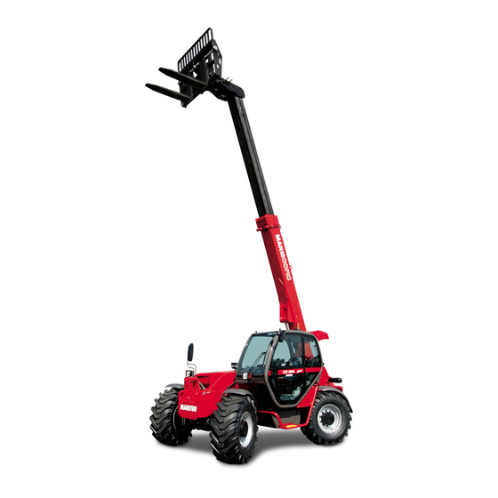
MHT-X 780 T-E3
MHT-X 860 LT-E3
MHT-X 950 LT-E3
OPERATOR'S MANUAL
THIS OPERATOR'S MANUAL MUST BE KEPT IN THE LIFT TRUCK AND MUST BE READ AND UNDERSTOOD BY OPERATORS.
PDF created with pdfFactory Pro trial version
www.pdffactory.com
Advertisement
Table of Contents

Related Manuals for Manitou MHT-X 780 T-E3


Summary of Contents for Manitou MHT-X 780 T-E3
- Page 1 41013 Castelfranco Emilia (MO) ( Tel.059/959811 - Fax 059/959850) YOUR DEALER 648645 EN (01/01/2012) MHT-X 780 T-E3 MHT-X 860 LT-E3 MHT-X 950 LT-E3 OPERATOR’S MANUAL THIS OPERATOR’S MANUAL MUST BE KEPT IN THE LIFT TRUCK AND MUST BE READ AND UNDERSTOOD BY OPERATORS.
- Page 2 MHT-X 780 T-E3 PDF created with pdfFactory Pro trial version www.pdffactory.com...
- Page 3 2 - DESCRIPTION PDF created with pdfFactory Pro trial version www.pdffactory.com...
-
Page 4: Electric Circuit
CHARACTERISTICS MHT-X 780 T-E3 I.C. ENGINE TRANSMISSION ELECTRIC CIRCUIT BRAKE CIRCUIT PDF created with pdfFactory Pro trial version www.pdffactory.com... -
Page 5: Sound And Vibration
SOUND AND VIBRATION (according to standard NF EN 12053) (according to directive 2000/14/EC modified by directive 2005/88/EC) (according to standard NF EN 13059) (according to standard ISO 5349-2) HYDRAULIC CIRCUIT HYDRAULIC MOVEMENTS SPECIFICATIONS AND WEIGHTS (according to standard ISO 8313) PDF created with pdfFactory Pro trial version www.pdffactory.com... -
Page 6: Dimensions And Load Chart
DIMENSIONS AND LOAD CHART MHT-X 780 T-E3 2-14 PDF created with pdfFactory Pro trial version www.pdffactory.com... -
Page 7: Instruments And Controls
INSTRUMENTS AND CONTROLS 2-20 PDF created with pdfFactory Pro trial version www.pdffactory.com... - Page 8 DESCRIPTION 1 - DRIVER’S SEAT 2 - SAFETY BELT 3 - CONTROL AND SIGNAL LIGHTS PANEL 4 - LONGITUDINAL STABILITY LIMITER AND WARNING DEVICE 5 - EMERGENCY STOP BUTTON 6 - EMERGENCY EXIT 7 - SWITCHES 8 - LIGHT SWITCH, HORN AND INDICATOR SWITCH 9 - FRONT AND REAR WINDSCREEN WIPER SWITCH 10 - IGNITION SWITCH 11 - FUSES AND RELAYS IN THE CAB...
- Page 9 1 - DRIVER’S SEAT WEIGHT ADJUSTMENT (FIG. A) SEAT HEIGHT ADJUSTMENT (FIG. B) SEAT BACK-REST ANGLE ADJUSTMENT (FIG. C) SEAT DEPTH ADJUSTMENT (FIG. D) EXTENDING THE HEAD-REST (FIG. E) 2-22 PDF created with pdfFactory Pro trial version www.pdffactory.com...
- Page 10 LUMBAR ADJUSTMENT (FIG. F) ADJUSTMENT OF THE ANGLE OF THE BACK-REST (FIG. G) If you do not support the back-rest when making adjustments, it swings completely forwards. LONGITUDINAL ADJUSTMENT (FIG. H) MAINTENANCE (FIG. I) A rocking head-rest increases the risk of an accident ! 2-23 PDF created with pdfFactory Pro trial version www.pdffactory.com...
- Page 11 1 - BASIC PNEUMATIC DRIVER’S SEAT (OPTION) WEIGHT ADJUSTMENT (FIG. A) SEAT HEIGHT ADJUSTMENT (FIG. B) To avoid causing any damage, do not activate the compressor for over 1 minute. SEAT BACK-REST ANGLE ADJUSTMENT (FIG. C) SEAT DEPTH ADJUSTMENT (FIG. D) EXTENDING THE HEAD-REST (FIG.
- Page 12 LUMBAR ADJUSTMENT (FIG. F) ADJUSTMENT OF THE ANGLE OF THE BACK-REST (FIG. G) If you do not support the back-rest when making adjustments, it swings completely forwards. HORIZONTAL SHOCK ABSORBER (FIG. H) LONGITUDINAL ADJUSTMENT (FIG. I) SERVICING (FIG. J) A rocking head-rest increases the risk of an accident ! 2 - SAFETY BELT In no event should the lift truck be used if the seat belt is defective (fixing, locking, cuts, tears, etc.).
- Page 13 3 - CONTROL AND SIGNAL LIGHTS PANEL CONTROL INSTRUMENTS A - I.C. ENGINE WATER TEMPERATURE B - HOUR METER AND REV COUNTER C - FUEL LEVEL D - CLOCK SIGNAL LIGHTS A permanently lit or flashing warning lamp, with the engine running, is the sign of an operating fault. The lighting of some lamps may be accompanied by an audible signal.
- Page 14 AVAILABLE INDICATOR LIGHT AVAILABLE INDICATOR LIGHT RED BRAKING OIL LEVEL WARNING INDICATOR LIGHT RED PARKING BRAKE LAMP BATTERY CHARGE WARNING INDICATOR LIGHT RED I.C. ENGINE OIL PRESSURE WARNING INDICATOR LIGHT RED I.C. ENGINE WATER TEMPERATURE WARNING INDICATOR LIGHT RED AIR FILTER OR HYDRAULIC RETURN FILTER CLOGGED INDICATOR LIGHT GREEN DIRECTION INDICATOR LAMP GREEN SIDELIGHTS LAMP GREEN LOW BEAM LAMP...
- Page 15 4 - LONGITUDINAL STABILITY LIMITER AND WARNING DEVICE The operator must respect the lift truck’s load chart, and the operating mode according to the attachment. “HANDLING” MODE “BUCKET” MODE “SUSPENDED LOAD” MODE A - “HANDLING” MODE B - “BUCKET” MODE All hydraulic movements remain available, ONLY PERFORM DE-AGGRAVATING HYDRAULIC MOVEMENTS IN THE FOLLOWING ORDER: RETRACT AND RAISE THE JIB.
- Page 16 C - “SUSPENDED LOAD” MODE D - KEY SELECTOR FOR DISCONNECTING THE LONGITUDINAL STABILITY LIMITER AND WARNING DEVICE Remain very vigilant during this operation. The only information available to the operator is the lift truck’s dynamic stability. The safety system can be deactivated manually only in case of emergency and for reasons of safety With the safety system deactivated, the operator and the truck are exposed to risks and there is nothing to prevent overloading and/or tipping over of the vehicle.
- Page 17 E - TESTING OF THE LONGITUDINAL STABILITY LIMITER AND WARNING DEVICE F - FAULT INDICATOR LAMP G - STRAIN GAUGE Disassembly or calibration of the strain gauge is prohibited, this must only be done by specially trained personnel, consult your dealer. 2-30 PDF created with pdfFactory Pro trial version www.pdffactory.com...
-
Page 18: Emergency Stop Button
5 - EMERGENCY STOP BUTTON Be ready for hydraulic movements suddenly stopping when you press this button. 6 - EMERGENCY EXIT 7 - SWITCHES A - PARKING BRAKE SWITCH B - FRONT WHEELS ALIGNMENT GREEN INDICATOR LIGHT C - REAR WHEELS ALIGNMENT YELLOW INDICATOR LIGHT D - REAR FOG LIGHT SWITCH F - TRANSMISSION RESET PUSHBUTTON LIGHT ON X - OPTION... - Page 19 F - DIRECTION SELECTION SWITCH Before selecting one of the three possible steering positions, bring all 4 wheels into alignment with regards to the lift truck axle. Never change the steering mode whilst driving. Before driving on roads, it is necessary to check the alignment of the rear wheels and to drive in front wheel steer.
-
Page 20: Legend Of Functions
20 - AIR CONDITIONING CONTROLS (OPTION AIR CONDITIONING) The air conditioning only comes on when the forklift truck has been started up. When using your air conditioning, you must work with the doors and windows closed. In winter: So as to ensure correct operation and complete efficiency of the air conditioning unit, start up the compressor once a week, if only for a short spell, so as to lubricate the internal seals. -
Page 21: Rear Lights
41 - FRONT HEADLIGHTS 42 - REAR LIGHTS 43 - REVOLVING LIGHT STANDARD OPTIONAL AIR CONDITIONING 2-45 PDF created with pdfFactory Pro trial version www.pdffactory.com...
Need help?
Do you have a question about the MHT-X 780 T-E3 and is the answer not in the manual?
Questions and answers