
Related Manuals for Manitou MHT 790 104JD H ST4 S1


Summary of Contents for Manitou MHT 790 104JD H ST4 S1
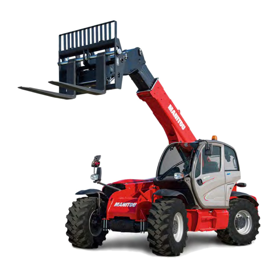
- Page 1 649010 EN/US/AU (16/07/2018) MHT 790 104JD H ST4 S1 OPERATOR'S MANUAL (ORIGINAL INSTRUCTIONS)
- Page 2 - Descriptions and figures are non binding. - MANITOU reserves the right to change its models and their equipment without being required to update this manual. - The MANITOU network, consisting exclusively of qualified professionals, is at your disposal to answer all your questions.
- Page 3 MANITOU BF. Any violation of the aforementioned may lead to civil and criminal prosecution. The logos as well as the visual identity of the company are the property of MANITOU BF and may not be...
- Page 4 1 - OPERATING AND SAFETY INSTRUCTIONS 1 - OPERATING AND SAFETY INSTRUCTIONS 2 - DESCRIPTION 2 - DESCRIPTION 3 - MAINTENANCE 3 - MAINTENANCE 4 - OPTIONAL ATTACHMENTS FOR USE WITH THE RANGE 4 - ADAPTABLE ATTACHMENTS IN OPTION ON THE RANGE 5 - LOAD CHARTS FOR INTERCHANGEABLE EQUIPMENT...
- Page 6 LEGEND OF SIGNS AND SYMBOLS OVERVIEW: Warning ! be careful ! your safety or the safety of the lift truck is at risk. See image 2-48 For more details: see paragraph “Switches” ATTACHMENT LOAD TABLE Reference Indication (example) Example load table machine type Forks Positioner...
- Page 7 ATTACHMENT PICK AND CARRY TABLE Reference Indication (example) Example load chart Pick and Carry type of attachment Forks Positioner load center L.C.600mm/24in (Optional) Pos. AK alphanumeric code which identifies the type of attachment in use machine model MHT 790 working conditions load table code 53008789 capacity table according to standards in force in the destination country...
- Page 9 1 - OPERATING AND SAFETY INSTRUCTIONS 1 - 1...
- Page 10 TABLE DES MATIÈRES 1 - OPERATING AND SAFETY INSTRUCTIONS INSTRUCTIONS TO THE COMPANY MANAGER THE SITE THE OPERATOR THE LIFT TRUCK A - THE TRUCK'S SUITABILITY FOR THE JOB ..........4 B - ADAPTATION OF THE LIFT TRUCK TO STANDARD ENVIRONMENTAL CONDITIONS .
- Page 11 LIFT TRUCK MAINTENANCE INSTRUCTIONS GENERAL INSTRUCTIONS PLACING THE JIB SAFETY WEDGE FITTING THE WEDGE............25 REMOVING THE WEDGE .
- Page 12 A - THE TRUCK'S SUITABILITY FOR THE JOB - MANITOU has ensured that this lift truck is suitable for use under the standard operating conditions defined in this operator's manual, with a STATIC test coefficient OF 1,33 and a DYNAMIC test coefficient OF 1, as specified in harmonised standard EN 1459 for variable range trucks.
- Page 13 C - MODIFICATION OF THE LIFT TRUCK - For your safety and that of others, you must not change the structure and settings of the various components used in your lift truck (hydraulic pressure, calibrating limiters, engine speed, addition of extra equipment, addition of counterweight, unapproved attachments, alarm systems, etc.) yourself.
- Page 14 - At any time, as an operator, you must envisage, within reason, the possible risk to yourself, to others or to the lift truck itself when you use it. In order to reduce or avoid any danger with a MANITOU-approved attachment, follow the instructions of paragraph: 4 - ADAPTABLE ATTACHMENTS IN OPTION ON THE RANGE: INTRODUCTION.
- Page 15 • With a PLATFORM-fitted lift truck, people can only be lifted using platforms designed by MANITOU for the purpose. - MANITOU sells equipment specifically designed for lifting people (OPTION PLATFORM lift truck, contact your dealer). OPERATING INSTRUCTIONS UNLADEN AND LADEN A - BEFORE STARTING THE LIFT TRUCK - Perform the daily service (see: 3 - MAINTENANCE: A - DAILY OR EVERY 10 HOURS SERVICE).
- Page 16 - Travelling on a longitudinal slope: • Drive and brake gently. • Moving without load: Forks or attachment facing downhill. • Moving with load: Forks or attachment facing uphill. - Take into account the lift truck’s dimensions and its load before trying to negotiate a narrow or low passageway. - Never move onto a loading platform without having first checked: •...
- Page 17 E - STARTING THE LIFT TRUCK SAFETY INSTRUCTIONS The lift truck must only be started up or manoeuvred when the operator is sitting in the driver’s cab, with his seat belt adjusted and fastened. - Never try to start the lift truck by pushing or towing it. Such operation may cause severe damage to the transmission.
- Page 18 - In all circumstances make sure you are in control of your speed. - On damp, slippery or uneven terrain, drive slowly. - Brake gently, never abruptly. - Only use the lift truck’s forward/reverse selector from a stationary position and never do so abruptly. - Do not drive with your foot on the brake pedal.
- Page 19 H - DRIVING THE LIFT TRUCK ON THE PUBLIC HIGHWAY (or see current legislation in other countries) FRENCH ROAD TRAFFIC RULES - The driving of non EC type-approved tractors on the public highway is subject to the provisions of the highway code relating to special machines, defined in article R311-1 of the highway code, in category B of the Equipment Order of 20 November 1969 that determines the procedures applicable to special machines.
- Page 20 INSTRUCTIONS FOR HANDLING A LOAD A CHOICE OF ATTACHMENTS - Only attachments approved by MANITOU can be used on its telehandlers. - Make sure the attachment is appropriate for the work to be done (see: 4 - ADAPTABLE ATTACHMENTS IN OPTION ON THE RANGE).
- Page 21 D - TRANSVERSE ATTITUDE OF THE LIFT TRUCK Depending on the model of lift truck The transverse attitude is the transverse slope of the chassis with respect to the horizontal. Raising the jib reduces the lift truck's lateral stability. The transverse attitude must be set with the jib in down position as follows: 1 - LIFT TRUCK WITHOUT ROLL CORRECTOR USED ON TYRES - Position the lift truck so that the bubble in the level is between the two lines (see: 2 - DESCRIPTION: INSTRUMENTS AND CONTROLS).
- Page 22 F - TAKING UP AND LAYING A HIGH LOAD ON TYRES You must not raise the jib if you have not checked the transverse attitude of the lift truck (see: INSTRUCTIONS FOR HANDLING A LOAD: D - TRANSVERSE ATTITUDE OF THE LIFT TRUCK). REMINDER: Make sure that the following operations can be performed with good visibility (see: OPERATIONS INSTRUCTIONS UNLADEN AND LADEN: D - VISIBILITY).
- Page 23 LAYING A HIGH LOAD ON TYRES - Approach the load in the transport position in front of the stack (fig. F6). - Apply the parking brake and place the forward/reverse selector in neutral. - Raise and extend the jib (1) (2) until the load is above the stack, while monitoring the longitudinal stability limiter and warning device (see: INSTRUCTIONS FOR HANDLING A LOAD: C - LONGITUDINAL STABILITY LIMITER AND WARNING DEVICE).
- Page 24 G - TAKING UP AND LAYING A HIGH LOAD ON STABILIZERS Depending on the model of lift truck You must not raise the jib if you have not checked the transverse attitude of the lift truck (see: INSTRUCTIONS FOR HANDLING A LOAD: D - TRANSVERSE ATTITUDE OF THE LIFT TRUCK).
- Page 25 TAKING UP A HIGH LOAD ON STABILISERS - Ensure that the forks will easily pass under the load. - Check the position of the lift truck with respect to the load and make a test run, if necessary, without taking the load. - Raise and extend the jib (1) (2) until the forks are at the level of the load (fig.
- Page 26 H - TAKING UP AND LAYING DOWN A SUSPENDED LOAD F a i l u r e t o f o l l o w t h e a b o v e i n s t r u c t i o n s m a y l e a d t h e l i f t t r u c k t o l o o s e s t a b i l i t y a n d o v e r t u r n . MUST be used with a lift truck equipped with an operational hydraulic movement cut-out device.
- Page 27 B - LIFT TRUCK SUITABILITY FOR USE - MANITOU has ensured that this platform is suitable for use under the normal operating conditions defined in this operator's manual, with a STATIC test coefficient OF 1,25 and a DYNAMIC test coefficient OF 1,1, as specified in harmonised standard EN 280 for "mobile elevating work platforms".
- Page 28 It is strictly forbidden to use the platform when the wind speed exceeds 45 km/h. - To visually recognise this wind speed, refer to the empirical wind evaluation scale below: BEAUFORT scale (wind speed at a height of 10 m on a flat site) Speed Speed Speed...
- Page 29 INSTRUCTIONS FOR USING THE RADIO-CONTROL For lift trucks with RC radio control Conformity Each Dynamic series radio remote control is in conformity with the (R&TTE) Directive 1999/5/EC and its essential requirements. Each radio remote control is also in conformity with the harmonised standards given in the EC Declaration of Conformity Radio link The two units constantly communicate with one another through a radio link.
- Page 30 WARNINGS In addition to all instructions provided by the machine manufacturer, by the installer of the radio remote control and by the person responsible for the safety of the work area, users shall always respect the following warnings. Before starting to work. - The transmitting unit shall be used in a simple and comfortable way, avoiding accidental falls.
- Page 31 - follow the instructions to detect possible malfunctions and their origins. Any fault should be repaired by authorised personnel only, contact the support service of MANITOU. - The following radio remote control data must be reported in order to make interventions faster and more reliable:...
- Page 32 When operating and moving the machine, remember that the radio remote control does not intervene autonomously when potential hazardous situations are displayed and signalled. Operation with display. If the transmitting unit has a display, it is possible to visualize signal icons, measurements collected from the machine and their description (See chapter: 2-DESCRIPTION).
- Page 33 LIFT TRUCK MAINTENANCE INSTRUCTIONS GENERAL INSTRUCTIONS - Ensure the area is sufficiently ventilated before starting the lift truck. - Wear clothes suitable for the maintenance of the lift truck, avoid wearing jewellery and loose clothes. Tie and protect your hair, if necessary. - Stop the engine and remove the ignition key, when an intervention is necessary.
- Page 34 LUBRICANT AND FUEL LEVELS - Use the recommended lubricants (never use contaminated lubricants). - Do not fill the fuel tank when the engine is running. - Only fill up the fuel tank in areas specified for this purpose. - Do not fill the fuel tank to the maximum level. - Do not smoke or approach the lift truck with a flame, when the fuel tank is open or is being filled.
- Page 35 The following recommendations are intended to prevent the lift truck from being damaged when it is withdrawn from service for an extended period. For these operations, we recommend the use of a MANITOU protective product, reference 603726. Instructions for using the product are given on the packaging.
- Page 36 BRINGING THE LIFT TRUCK BACK INTO SERVICE - Remove the waterproof adhesive tape from all the holes. - Refit the intake hose. - Refit and reconnect the battery. - Remove the protection from the cylinder rods. - Perform the daily service (see: 3 - MAINTENANCE: A - DAILY OR EVERY 10 HOURS SERVICE). - Put the handbrake on and remove the axle stands.
- Page 37 • Glass items can be removed and collected for processing by glaziers. ENVIRONMENTAL PROTECTION By entrusting the maintenance of your lift truck to the MANITOU network, the risk of pollution is limited and the contribution to environmental protection contribution is made.
- Page 39 2 - USE...
- Page 41 SAFETY PLATES AND STICKERS IMPORTANT Clean all of the stickers and safety plates to make them legible. It is essential to replace stickers and safety plates which are illegible or damaged. Check the presence of stickers and safety plates after replacing any spare parts. EXTERNAL PLATES AND STICKERS POINT REFERENCE...
- Page 42 STICKERS AND PLATES UNDER THE ENGINE HOOD POINT REFERENCE DESCRIPTION 716905 Danger hot surface 716919 Attention to the air inlet 293887 Engine coolant 716926 Risk of leakage of the coolant 716906 Shear hands 296741 Walking surface 716907 Flammable liquid hazard 909050 Risk of electric shock 53026391...
- Page 43 STICKERS AND PLATES IN THE CAB POINT REFERENCE DESCRIPTION 268491 - Instructions oil brake 239595 - Sound power 105dB 302780 - Instructions driver presence / start 297735 - Instructions operation mode 290183 - Dump set on telescope 184276 - Control direction selector 193032 - Conformity cab 223324...
- Page 45 « EC» DECLARATION OF CONFORMITY CE DECLARATION OF CONFORMITY DECLARATION "CE" DE CONFORMITE (originale) " " "...
- Page 46 bg : 1) удостоверение за « СЕ » съответствие (oригинална), 2) Фирмата, 3) Адрес, 4) Техническо досие, 5) Фабрикант на описаната по-долу машина, 6) Обявява, че тази машина, 7) Отговаря на следните директиви и на тяхното съответствие национално право, 8) За машините към допълнение IV, 9)Номер на удостоверението, 10) Наименувана...
- Page 47 For any further technical information regarding your lift truck refer to chapter: 2 - DE- SCRIPTION: CHARACTERISTICS. I.C. ENGINE • Model • Serial No. GEAR BOX • Type • MANITOU reference • Serial No. FRONT AXLE • Type • Serial No. • MANITOU reference...
- Page 48 REAR AXLE • Type • Serial No. • MANITOU reference • Type • Serial No. BOOM • MANITOU reference • Date of manufacture CHASSIS • Lift truck serial no. CONNECTION MANFACTURER’S PLATE Model Serial Nr. Year manufacture Unladenweight Centre of gravity...
- Page 49 CHARACTERISTICS ENGINE Engine JOHN DEERE St.4 (Tier IV) Type 4045PWL-104 kW Fuel Diesel No. of cylinders 4 vertical in line Injection system Direct Firing order 1 3 4 2 Displacement L - cm 4.5 - 4500 Bore mm - in 106 - 4.17 Stroke mm - in...
- Page 50 Standard Front & Rear tyres Type Aeolus Dimensions 445/65R22.5 TL AGP23 Pressure bar - psi 9.9 -143.58 Optional Front & Rear tyres Type Michelin Dimensions 18R22.5 175A8/182A2 TL XF Pressure bar - psi 7.5 - 108.77 ELECTRICAL CIRCUIT Electrical circuit Ground Negative Battery standard...
- Page 51 HYDRAULIC MOTIONS SPEEDS Unladen lifting Laden lifting 10.2 Unladen lowering Laden lowering Unladen extending Laden extending Unladen retracting Laden retracting Reverse tilt time unladen Forward tilt time unladen SPECIFICATIONS AND WEIGHT Speed of movement for telehandler in standard configuration on flat ground (except special conditions) Driving Speed 30 - 18.64 Maximum speed...
- Page 52 2-14...
- Page 53 DIMENSIONS 1200 47,24 2870 112,99 1128 44,41 39,25 5273 207,60 5142 202,44 4739 186,57 6473 254,84 2020 79,53 2473 97,36 15,04 16,10 17,13 1275 50,20 34,80 1750 68,90 2,36 1839 72,40 38° 26° 4801 189,02 8647 340,43 3481 137,05 2478 97,56 2657 104,61...
- Page 54 LOAD CHARTS MACHINE ON WHEELS 2-16 2-16...
- Page 55 2-17 2-17...
- Page 56 2-18 2-18...
- Page 57 This page intentionally left blank – – – LOA D CHART ARE AVAILABLE UPON REQUEST 2-19 2-19...
- Page 58 CONTROLS AND DISPLAYS (Depending on the model of machine) (Depending the equipment) 2 - 1 2-20...
- Page 59 CONTROLS AND DISPLAYS OVERVIEW ( 2 - 1): 1. AIR DIFFUSERS FOR HEATING 2. AIR DIFFUSERS FOR DEMISTING 3. HEATER CONTROL AIR 4. CONDITIONING CONTROLS 5. CONTROL PANEL AND LOAD LIMITER 6. START-UP SWITCH 7. PROPORTIONAL ELECTRO-HYDRAULIC JOYSTICK 8. SWITCHES 9.
- Page 60 1 - DRIVER’S SEAT There are three types of driver’s seat: A - Driver’s seat (standard) ( 2 - 2) B - Low frequency driver’s pneumatic seat (optional) ( 2 - 3) C - Driver’s pneumatic seat (optional) ( 2 - 4) DRIVER’S SEAT (STANDARD) Designed for maximum comfort, this seat can be adjusted as follows.
- Page 61 LOW FREQUENCY DRIVER’S PNEUMATIC SEAT (OPTIONAL) Designed for maximum comfort, this seat can be adjusted as follows. SEAT HEIGHT ADJUSTMENT Sit down correctly in the seat. Switch on lift truck ignition. Pull or push the lever (1, 2 - 3) according to the desired height, ensuring that ...
- Page 62 EXTENDING THE HEAD-REST The height of the head-rest (5, 2 - 4) can be adjusted by pulling it upwards (the notches will click) up to the stop. The head-rest can be removed by applying sufficient pressure to pull it off the stop.
- Page 63 5 - CONTROL PANEL AND LOAD LIMITER The manitou safety system performs the functions of the telehandler control and load movement limiter for the frontal telehandler. SAFETY SYSTEM LAYOUT • MC2M control board (1, 2 - 7) • TERA7 instrument control panel + Slave IO-CORE control board (2, 2 - 7) ...
- Page 64 INSTRUMENT CONTROL PANEL The control panel TERA7 (1, 2 - 8) with colour screen display shows and informs the operator of all telehandler's working phases. Five pages are saved in the panel memory (1, 2 - 8) and these can be ...
- Page 65 DRIVING PAGE (F1) engine coolant temperature gauge indicator (1, 2 - 10) warning light for potential engine coolant overheating (2, 2 - 10) fuel level indicator (3, 2 - 10) the indicator lamp light is on (4, 2 - 10) when the fuel level in the tank is lower than 10% of its capacity (about 50 litres) ...
- Page 66 alternator excitation I.C. engine oil pressure brake fluid engine intake air filter transmission oil filter parking brake telehandler door hydraulic oil filter steering emergency trailer brake anomaly (optional) DPF: quantity of soot is high DPF: active regeneration DPF: regeneration disabled Diesel exhaust fluid (DEF) level indicator ( next paragraph: SCR SYSTEM DERATES)
- Page 67 DEF & SCR SYSTEM DERATES (Emissions control system of the exhaust gas) The DEF and SCR systems on Final Tier 4 engines are required to reduce NOx DTC* LIST emissions generated by the engine. Faults When certain components of these systems malfunction, the NOx emissions in- DEF Tank Fluid Level Signal Out of Range High crease and the engine is out of emissions compliance.
- Page 68 Diesel Exhaust Fluid Level (DEF) If the diesel exhaust fluid level is less than 10%, a warning is issued and the torque is reduced by 25%. If there is no diesel exhaust fluid, the power is halved and the engine speed will drop by 100 rpm every minute until it reaches min rpm.
- Page 69 WORKING PAGE (F2) Load conditions 1b 1c The coloured bar indicates the percentage of the load lifted in reference to the machine's operating condition: • Green reference (1a, 2 - 11): safety area. • Yellow reference (1b, 2 - 11): alarm area, load lifted 90% more than permitted load (external warning sound active).
- Page 70 SETTING PAGE (F4) Menu screen (1, 2 - 12): • Configurations (1a, 2 - 12) • Transducers (1b, 2 - 12) • Weight (1c, 2 - 12) (Only with password) • Service (1d, 2 - 12) (Only with password) 1c 1b ...
- Page 71 - Transducers (1d, 2 - 12) - (These settings can be used for the diagnostic machine) - Push the "Scroll" keys (1, 2 - 13) to select "TRANSDUCERS" (1a, 2 - 13) and to access the functions: ...
- Page 72 ALARM PAGE (F5) The indicators with the red light on the central unit or the component indicate an error or an anomaly. Warning list 2 - 17) Example: 123 [code warning] LMI_TXTAL1 [description warning] Alarm list 2 - 17) ...
- Page 73 6- SELECTOR TO DISABLE THE LOAD LIMITER The load limiter can only be deactivated manually in exceptional cases and for reasons of safety. When the load limiter is deactivated, the operator and the telehandler are exposed to risks and there is nothing to prevent overload and/or the telehandler overturning.
- Page 74 7 - KEYPAD The keypad ( 2 - 19) is located in the cab on the armrest (10, 2 - 19). KEYS FUNCTION Parking brake key (1, 2 - 19) Hydraulic movements stop key (2, 2 - 19) ...
- Page 75 - OPTIONAL OUTPUT 2 AND 3 SELECTOR (OPTIONAL) The selector ( 4, 2 - 19) is used for switching the hydraulic control, which carries out two or three hydraulic movements using the accessory. Depending on the machine setup, select the 2 and 3 optional output by ...
- Page 76 Movements permitted depending the working modes Telehandler controlled from cab (operating modes: on stabilizer and on wheels) “HANDLING” MODE - Working condition: Movement Status Lifting telescopic boom Lowering telescopic boom Extending telescopic boom Retracting telescopic boom ...
- Page 77 Retracting telescopic boom Backward tilting accessory Forward tilting accessory Optional 1 Optional 2 : permitted : not permitted - The actuation of the anti-overturning system bypass key allows to rearm of movements for 10 seconds - The open door does not stop the movements - Every movement is allowed with the telescopic boom retracted and the overturning system bypassed...
- Page 78 8 - SWITCHES The location of the switches may vary depending on the options (1, 2 - 21). 2 - 21 HAZARD WARNING LIGHTS BUTTON This button ( 2 - 22) enables the L.H. and R.H. indicators to be switched on simultaneously, with the ignition off.
- Page 79 WINDOW LIFT (POWER-OPERATED) SWITCH This switch (1, 2 - 26) activates the control that raises or lowers the cab door window, using a powered mechanism. - Opening the window. • Press the switch forward (1a, 2 - 26) and hold it until the window has moved to the desired position.
- Page 80 OPTIONAL FUNCTIONS SWITCHES RADIO REMOTE CONTROL SWITCH This switch (2, 2 - 28) activates the radio remote control. On the switch (2, 2 - 28) the LED switches on (1, 2 - 28) to indicate that the function is active.
- Page 81 EASY HYDRAULIC ATTACHMENT CONNECTION SWITCH For easily connecting and disconnecting the attachment. The switch (2, 2 - 31) has two positions. On the switch (2, 2 - 31), the LED switches on (1, 2 - 31) to indicate that the function is active.
- Page 82 HYDRAULIC ACCESSORY BLOCK SWITCH Precautions to be taken if the machine is provided with the “hydraulic accessory block” device. This hydraulic device with electric control makes it possible for the operator to block/release an accessory from the driving seat. The device activates two pins (X, Y, 2 - 34) which move horizontally on the quick-release coupling, outwards (blocking the accessory) and inwards...
- Page 83 CAB FRONT AND REAR WORK LIGHTS SWITCH This switch (1, 2 - 36) controls the operation of the front and rear work lights. The switch (1, 2 - 36) has three positions: • front work lights (1a, 2 - 36);...
- Page 84 TRUCK/PLATFORM SELECTOR SWITCH KEY (only with platform) • Handling or platform operation from driver’s cab controls (1, 2 - 41). • Platform operation from control console (2, 2 - 41). (For more details: Baskets user manual) 2 - 41 BUTTON FOR RESTORING ELECTRIC POWER SUPPLY (only with platform) If the “emergency stop”...
- Page 85 10 - WARNING AND INDICATOR LAMPS INDICATOR LAMPS POSITION LIGHTS (For more details: paragraph “Lighting, horn and indicator lights lever”) position lights are off position lights active green indicator light LOW BEAMS (For more details: paragraph “Lighting, horn and indicator lights lever”) low beams are off low beams active green indicator light HIGH BEAMS...
- Page 86 STEERING WHEEL TYPES (For more details: paragraph “Keypad”) front wheel steering active green indicator light concentric wheel steering active green indicator light crab steering active green indicator light FAST GEAR (For more details: paragraph “Keypad”) gear engaged active green indicator light SLOW GEAR (For more details: paragraph “Keypad”)
- Page 87 SERVICE (For more details: see next paragraph “Warning lamps in alarm page: Service”) Service orange indicator light HYDRAULIC CONTROL ATTACHMENT DISCONNECTED (For more details: paragraph “Keypad”) black indicator light indicates that the optional hydraulic movement is excluded OPTIONAL WORKING (OPTIONAL) (For more details: paragraph “Keypad”) optional working orange indicator active...
- Page 88 DIESEL PARTICULATE FILTER (DPF) INDICATOR LAMPS DPF: HIGH QUANTITY OF SOOT (For more details: paragraph “Switches”) high quantity of soot active orange indicator light This indicator provides a general indication of the amount of soot. When the quantity of soot is normal, the indicator switches off. DPF: ACTIVE REGENERATION active regeneration active orange indicator light This indicator lights up during active regeneration.
- Page 89 WARNING LAMPS I.C. ENGINE SEVERE FAULT If the indicator lights up or flashes when the telescopic lift is in operation, there is a severe fault. Switch off the I.C. engine immediately and contact your dealer. normal functioning of the I.C. engine I.C.
- Page 90 TRANSMISSION FILTER BLOCKING normal functioning of the transmission oil filter blocked transmission oil filter active red warning light This light indicates the status of the filter cartridge: if the cartridge is encrusted or damaged, the warning lights up (for replacing the cartridge, refer to the “Lubricants”...
- Page 91 “EMERGENCY STOP” (For more details: paragraph “Emergency stop” button) “emergency stop” red button not pressed “emergency stop” red button pressed red warning light LOAD LIMITER DISABLED (For more details: paragraph “Selector to disable the load limiter”) normal functioning of the load limiter DANGER! Load limiter disabling red warning light ALARM AND WARNING MACHINE...
- Page 92 BASKET CONTROL UNIT (OPTIONAL) (Second equipment) operating normally red warning light on indicates an error or an anomaly ACKNOWLEDGEMENT OF ATTACHMENT (OPTIONAL) operating normally red warning light on indicates an error or an anomaly JOYSTICK operating normally red warning light on indicates an error or an anomaly RADIO REMOTE CONTROLS (OPTIONAL) (Second equipment) operating normally...
- Page 93 11 - START-UP SWITCH The switch (1, 2 - 44) has five positions, and its functions are: • 0 : I.C. engine STOP; • I : Main electric contact “+” (also activates the preheat device, if installed) • II : not used •...
- Page 94 12 - ACCELERATOR PEDAL Electronic pedal (1, 2 - 45), used for changing the telehandler speed by operating on the rpm of the I.C. engine. Press on the accelerator pedal (1, 2 - 45) to move the telehandler forward. 13 - SERVICE BRAKE PEDAL ...
- Page 95 14 - LIGHTING, HORN AND INDICATOR LIGHTS LEVER The lever (1, 2 - 46) controls: • All lights are off, the direction indicator lights are not flashing (A, 2 - 46). • The right hand direction indicator lights flash (B, 2 - 46).
- Page 96 16 - FORWARD/NEUTRAL/REVERSE GEAR SELECTOR This gear switch (1, 2 - 48) is on the joystick in the cabin. FORWARD GEAR: push the switch forward (F, 2 - 48), the gear set is displayed on the control panel ( Control panel and load limiter, 2-25).
- Page 97 17 - TRAVELLING MODE BUTTONS These buttons (+, -, 2 - 49) select the two operating modes: - slow mode by pressing the button (-, 2 - 49) - fast mode by pressing the button (+, 2 - 49). When the telehandler starts, the default mode is set to fast.
- Page 98 18 - PROPORTIONAL ELECTRO-HYDRAULIC JOYSTICK (According to the telehandler model) The joystick (1, 2 - 50) is located in the cab on the armrest (2, 2 - 50). The hydraulic control use authorisation is given by the validation of the driver’s ...
- Page 99 19 - HEATER CONTROL FAN CONTROL 2 - 52 This 3-speed control allows the air to be ventilated through the air vents. TEMPERATURE CONTROL 2 - 52 Allows the temperature inside the cab to be adjusted. The fan pumps in the air at an ambient temperature 2 - 51 ...
- Page 100 21 - AIR DIFFUSERS FOR DEMISTING Windscreen (1, 2 - 53). For optimum performance, close the heating diffusers (2, 2 - 53). 22 - AIR DIFFUSERS OF HEATING The heating diffusers (2, 2 - 53) make it possible to distribute the ventilated air inside the cab and on the side windows.
- Page 101 Emergency exit Use the rear window as an emergency exit (3, 2 - 56), if it is impossible to leave the cab through the door. 2 - 56 28 - CEILING LIGHT 2 - 57) 2 - 57 29 - ARMREST AND STORAGE ...
- Page 102 32 - CAB FILTER VENTILATORS (Standard) Cab internal ventilation filter. Remove the door (1, 2 - 60) that provides access to the filter ventilators 2 - 60). 2 - 60 33 - CAB FILTER VENTILATORS (Option air conditioning) Cab external ventilation filter.
- Page 103 37 - 37- FRONT HEADLIGHTS • Left front indicator (A, 2 - 63). • Left front dipped headlight (B, 2 - 63). • Left front main beam (C, 2 - 63). • Left front sidelight (D, 2 - 63).
- Page 104 39 - ROTATING BEACON LIGHT Standard The rotating beacon light (A, 2 - 65) pivots to save space on the telehandler and can be detached to prevent theft. - Loosen nut (1, 2 - 65) and remove the revolving light. ...
- Page 105 44 - BATTERY CUT-OFF For quickly disconnecting the battery (1, 2 - 69) when working on the electric circuit or when soldering, for example. Operate the battery cut-off no less than 30 seconds after having switched off the ignition with the ignition key. 2 - 69 45 - BOOM SAFETY WEDGE ...
- Page 106 46 - PORTABLE POWDER FIRE EXTINGUISHER Thee portable powder fire extinguisher (1, 2 - 71) is positioned behind the driver seat (2, 2 - 71). The portable powder fire extinguisher (1, 2 - 71) is suitable for use on live electric appliances.
- Page 107 47 - FUSES AND RELAYS FUSE BOX AND RELAYS (CAB) - Remove the cover (1, 2 - 81) giving access to the fuses and relays 2 - 81). Always replace a faulty fuse with an equivalent one. Never use a repaired fuse.
- Page 108 FUSE BOX AND RELAYS OUT OF FUSE BOX - Remove the cover (1, 2 - 82) giving access to the fuses and relays 2 - 82). Always replace a faulty fuse with an equivalent one. Never use a repaired fuse.
- Page 109 These plates must not be: - removed from their position (removal immediately waives the warranty) - altered or ruined (contact MANITOU for replacement). Plates of the transmitting unit Three plates are located in the transmitting unit.
- Page 110 General description of the system The radiocontrol system includes: TRANSMITTING UNIT (PUSHBUTTON PANEL) (1, 2 - 85) RECEIVING UNIT (2, 2 - 85) ANTENNA (3, 2 - 85) BATTERY CHARGER (4, 2 - 85) Input ..........80-250V 7W Output .
- Page 111 TRANSMITTING UNIT CONTROL FUNCTIONS (RADIO CONTROL) ( 2 - 87) Machine function and load status display (1,1.1, 2 - 87) Joystick, selector switches, machine function buttons (2, 2 - 87) Emergency stop button (3, 2 - 87) ...
- Page 112 READING MAIN OPERATING DATA ( 2 - 88) - Height off the ground (H)*, (reading in “Meters ”, with a decimal position) - Boom angle (A), (reading in “Degrees”, with a decimal position) - Boom length (L)*, (reading in “Meters”, with a decimal position) - Operating radius (R)*, Measurement of the distance from the fifth wheel centre to the projection of the point of application of the load (reading in “Meters”, with a decimal position).
- Page 113 1.8 - Red warning light(1.8, 2 - 88) When on, this light indicates: - Stabilizers are not properly positioned (Depending on the machine model). - The basket access door was not properly closed. - The gear of the truck is engaged. Note: only for the ORH COUVREUR BASKET: the functions of the red light ...
- Page 114 4 - Radiocontrol power on S-KEY ( 2 - 90) Turn the key to turn on the radiocontrol (4 , 2 - 90). When the radiocontrol is not used, pull out the S-KEY for safety 2 - 90) 5 - Engine start-up authorisation and horn (5, ...
- Page 115 ATTACHMENT AUTOMATIC IDENTIFICATION (OPTIONAL) The machine is equipped with an electronic system for the recognition at the time of the hook attachment that identifies the type of attachment installed. - This system facilitates and fast the attachments change. The system is characterized by two devices fixed one on the machine boom ...
- Page 116 TOWING PIN AND HOOK Located at the rear of the lift truck, this device is used to attach a trailer. Its capa- city is limited for each lift truck by the Authorized Gross Vehicle Weight, tractive force and maximum vertical force on the coupling point. - To use a trailer, see current regulations in your country (maximum running spe- ed, braking, maximum weight of trailer, etc.).
- Page 117 3 - MAINTENANCE...
- Page 118 3 - 2...
- Page 119 TABLE OF CONTENTS 3 - MAINTENANCE ORIGINAL MANITOU SPARE PARTS AND EQUIPMENT FILTERS CARTRIDGES AND BELTS LUBRICANTS AND FUEL SERVICING SCHEDULE A - DAILY OR EVERY 10 HOURS SERVICE B - EVERY 50 HOURS SERVICE C - EVERY 250 HOURS OF SERVICE...
- Page 120 • Improvements due to experience feedback. • Operator training. • Only the MANITOU network has detailed knowledge of the design of the lift truck and therefore the best technical ability to provide maintenance. ORIGINAL REPLACEMENT PARTS ARE DISTRIBUTED EXCLUSIVELY BY MANITOU AND ITS DEALER NETWORK.
- Page 121 FILTERS CARTRIDGES AND BELTS I.C. ENGINE I.C. ENGINE OIL FILTER DRY AIR FILTER CARTRIDGE Part number: 796241 Part number: 299936 Change: 500 H Change: 1000 H FUEL FILTER SAFETY DRY AIR FILTER CARTRIDGE Part number: 52523728 Part number: 299937 Change: 500 H Change: 3000 H FUEL PRE-FILTER DIESEL EXHAUST FLUID SUPPLY PUMP FILTER...
- Page 122 USE THE RECOMMENDED LUBRICANTS AND FUEL: - For topping up, oils may not be miscible. - For oil changes, MANITOU oils are perfectly appropriate. DIAGNOSTIC ANALYSIS OF OILS If a service or maintenance contract has been organized with the dealer, a diagnostic analysis of engine, transmission and axle oils may be requested depending on the rate of use.
- Page 123 209 L 0.26 U.S. gal 0.52 U.S. gal 1.32 U.S. gal 5.28 U.S. gal 14.52 U.S. gal 55.21 U.S. gal - MANITOU OIL EVOLOGY 10W40 API CJ4 895837 895838 895839 895840 - MANITOU OIL HYDRAULIC ISO VG 46 545500 582297...
- Page 124 SERVICING SCHEDULE (1): MANDATORY 500 HOUR OR 6 MONTH SERVICE. This service must be carried out after approximately the first 500 hours of operation or within the 6 months following the start-up of the machine (whichever occurs first). (2): Every 10 hours during the first 50 hours then a final time at 250 hours. (3): Contact your dealer.
- Page 125 A = ADJUST, C = CHECK, G = GREASE, N = CLEAN, PAGE P = BLEED, R = REPLACE, V = DRAIN BRAKE - Brake oil level 3-18 - Brake oil V (3) P (3) - Brake system C (3) - Brake system pressure A (3) - Brake...
- Page 126 A - DAILY OR EVERY 10 HOURS SERVICE A1 – ENGINE OIL LEVEL CHECK Place the lift truck on level ground with the I.C. engine stopped, and let the oil drain into the sump. - Open the engine bonnet. - Pull out dipstick 1. - Clean the dipstick and check the correct level between the two notches.
- Page 127 To be carried out every 10 hours during the first 50 hours service, then once at 250 hours. If the lift truck is used in an abrasive environment (dust, sand, and coal.), use lubricating varnish (MANITOU reference: 483536). In this respect, consult your dealer.
- Page 128 B - EVERY 50 HOURS SERVICE Carry out the operations described previously as well as the following operations. B1 – RADIATOR CORE CHECK - CLEAN In a polluting atmosphere, clean the radiator core every day. Do not use a water jet or high-pressure steam as this could damage the radiator fins. - Open the engine bonnet.
- Page 129 B3 – GENERAL GREASING GREASE To be carried out weekly, if the lift truck has been operated for less than 50 hours during the week. In the event of prolonged use in an extremely dusty or oxidising atmosphere, reduce this interval to 10 working hours or every day. Clean and lubricate the following points with grease (see: 3 - MAINTENANCE: LUBRICANTS AND FUEL) and remove the surplus of grease.
- Page 130 B4 – HYDRAULIC OIL LEVEL CHECK Place the lift truck on level ground with the I.C. engine stopped, and the jib retracted and lowered as far as possible. Use a clean funnel and clean the underside of the oil drum before filling. - Check the level on the low level gauge 1.
- Page 131 B7 – CAB VENTILATION FILTERS CLEAN EXTERNAL CAB VENTILATION FILTER - Lift out cab ventilation filter 1. - Clean the filter with a compressed air jet. - Check its condition and change if necessary (see: 3 - MAINTENANCE: FILTERS CARTRIDGES AND BELTS).
- Page 132 C - EVERY 250 HOURS OF SERVICE Carry out the operations described previously as well as the following operations. C1 – CAB VENTILATION FILTERS CHANGE EXTERNAL CAB VENTILATION FILTER - Remove protective casing 1 using the ignition key. - Lift out cab ventilation filter 2 and replace it with a new one (see: 3 - MAINTENANCE: FILTERS, CARTRIDGES AND BELTS).
- Page 133 This page is intentionally blank 3 - 17...
- Page 134 Contrôler sur chaque partie tous les cordons de soudure et les points de fixation. En cas de détection de pièce ou composants détériorés, contacter le concessionnaire. Manitou suggère d’inspecter les parties de la machine indiquées ci-dessus si la machine a été impliquée dans un accident et/ou toutes les 500 heures de travail.
- Page 135 I.C. engine. USE THE RECOMMENDED LUBRICANTS: Oil MANITOU GOLD "API CJ-4 ; ACEA E9" => CHANGE EVERY 250 HOURS Oil JD Plus-50 II Premium => CHANGE EVERY 500 HOURS Dispose of the drain oil in an ecological manner.
- Page 136 D4 – FUEL PRE-FILTER CHANGE Carefully clean the outside of the pre-filter and its holder, to prevent dust from getting into the system. Make sure the electrical contact on the lift truck is cut, otherwise fuel will be released if the lift pump is on. - Open the engine bonnet.
- Page 137 D6 – AUTOMATIC ALTERNATOR BELT TENSIONER CHECK - Open engine bonnet and the lower cover 1. - Remove the protective casing 2. ALTERNATOR BELT TENSION - The belt tensioner is designed to work within the travel limits of the arm between the two fixed end-stops 3.
- Page 138 D7 – FRONT AND REAR AXLE DIFFERENTIAL OIL DRAIN Place the lift truck on level ground with the I.C. engine stopped and the differential oil still warm. Dispose of the drain oil in an ecological manner. - Place a container under the drain plugs 1 and unscrew them. - Remove level plug 2 and filling plug 3 to ensure that the oil is drained properly.
- Page 139 This page is intentionally blank 3 - 23...
- Page 140 E - EVERY 1000 HOURS OF SERVICE Carry out the operations described previously as well as the following operations. E1 – FUEL TANK CLEAN Place the lift truck on level ground with the I.C. engine stopped. While carrying out these operations, do not smoke or work near a flame. Never try to carry out welding or any other operation by yourself, as this could cause an explosion or a fire.
- Page 141 E3 – ENGINE CRANKCASE VENTILATION FILTER CHANGE - Open the engine bonnet. - Carefully clean the outside of the filter and its holder, to prevent dust from getting into the system. - Loosen filter 1 and discard it as well as its seal. - Lightly lubricate the new seals with clean engine oil and refit the assembly with a new filter (see: 3 - MAINTENANCE: FILTERS AND BELTS).
- Page 142 E4 – HYDRAULIC OIL DRAIN E5 – HYDRAULIC RETURN OIL FILTER CARTRIDGE CHANGE E6 – BREATHER FOR THE HYDRAULIC OIL TANK CHANGE E7 – SUCTION STRAINER FOR HYDRAULIC OIL TANK CLEAN Place the lift truck on level ground with the I.C. engine stopped and telescope jib retracted and lowered as far as possible.
- Page 143 FILLING UP THE OIL - Refit and tighten the drain plug 2 (tightening torque 29 to 39 N.m). - Fill up with oil (see: 3 - MAINTENANCE: LUBRICANTS AND FUEL) through filler port 10. - Observe the oil level on dipstick 11; the oil level should be at the level of the black point. - Check for any possible leaks at the drain plug.
- Page 144 F - EVERY 2000 HOURS OF SERVICE Carry out the operations described previously as well as the following operations. F1 – COOLING LIQUID DRAIN These operations are to be carried out if necessary or every two years at the beginning of winter.
- Page 145 F2 – WHEEL NUTS TIGHTENING TORQUE CHECK - Check the condition of the tyres, to detect cuts, protuberances, wear, etc. - Check the tightening torque of the wheel nuts with a torque wrench. • Front wheels: 630 N.m ± 15% •...
- Page 146 G - EVERY 3000 HOURS OF SERVICE Carry out the operations described previously as well as the following operations. G1 – SAFETY DRY AIR FILTER CARTRIDGE CHANGE - For the disassembly and reassembly of the dry air filter cartridge, see: 3 - MAINTENANCE: D3 - AIR FILTER CARTRIDGE.
- Page 147 This page is intentionally blank 3 - 31...
- Page 148 H - EVERY 4000 HOURS OF SERVICE Carry out the operations described previously as well as the following operations. H1 – DIESEL EXHAUST FLUID SUPPLY PUMP FILTER REPLACE Place the lift truck on level ground with the engine stopped. Diesel exhaust fluid is corrosive, protect the bodywork and wear personal protective equipment (gloves and goggles).
- Page 149 This page is intentionally blank 3 - 33...
- Page 150 I - OCCASIONAL MAINTENANCE I1 – ALTERNATOR BELT CHANGE - Open engine bonnet and the lower cover 1. - Remove the protective casing 2. - Place a 1/2 in. socket wrench in the square of the automatic tensioner 3 to slacken the belt and remove it.
- Page 151 I2 – REGENERATE THE EXHAUST PARTICULATE FILTER REGENERATION Manual regeneration is started by pressing the regeneration switch. Forced regeneration can be carried out only after the soot load has reached such a point as to cause the DPF indicator to light up Forced regeneration is necessary only if automatic regeneration has not been completed.
- Page 152 H3 – WHEEL CHANGE For this operation, we advise you to use the hydraulic jack MANITOU reference 505507 and the safety support MANITOU reference 554772. In the event of a wheel being changed on the public highway, secure the lift truck vicinity: - Stop the lift truck, if possible on firm, level ground.
- Page 153 H4 – FRONT HEADLIGHTS ADJUSTING RECOMMENDED SETTING (as per standard ECE-76/756 76/761 ECE20) Set to -2 % of the dipped beam in relation to the horizontal axis of the headlamp. ADJUSTING PROCEDURE - Place the unladen lift truck in the transport position and h2 = h1 - (l x 2 / 100) perpendicular to a white wall on flat, level ground.
- Page 154 H6 – LIFT TRUCK TOWING Towing must be done at very low speeds for short distances. - Set the reverse gear lever in neutral. - Disengage the parking brake. - Switch on the emergency lights. - Position the gear in neutral manually: a) disconnect and plug the hydraulic hoses “1”...
- Page 155 H8 – LIFT TRUCK ON A PLATFORM TRANSPORTING Ensure that the safety instructions connected to the platform are respected before the loading of the lift truck and that the driver of the means of transport is informed about the dimensions and the weight of the lift truck (see: 2 - DESCRIPTION: CHARACTERISTICS).
- Page 156 - make sure that the receiving unit panel symbols can be easily recognised and replace the panel if necessary - check that the plates on the receiving unit are readable and intact. Special maintenance Any fault should be repaired by authorised personnel only (Contact the support service MANITOU). Troubleshooting When the radio remote control does not work: - bring the transmitting unit close to the receiving unit to avoid radio interference and disturbances - establish whether the problem lies with the radio remote control or with the machine.
- Page 157 Malfunction signalled by the transmitting unit (Pushbutton) Identify the radio remote control malfunction according to the light signals on the units. If the problem persists after the suggested solution has been carried out, contact the support service of MANITOU. Signals...
- Page 158 3 - 42...
- Page 159 4 - O P T I O N A L ATTACHMENTS FOR USE WITH THE RANGE...
- Page 160 4 - 2...
- Page 161 TABLE OF CONTENTS 4 - OPTIONAL ATTACHMENTS FOR USE WITH THE RANGE INTRODUCTION PICKING UP THE ATTACHMENTS TECHNICAL SPECIFICATIONS OF ATTACHMENTS ATTACHMENT SHIELDS 4 - 3...
- Page 162 4 - 4...
- Page 163 - A wide range of attachments, specially designed and perfectly suitable for your lift truck is available and guaranteed by MANITOU. Only attachments approved by MANITOU are to be used on our lift trucks The manufacturer’s liability will be denied in case of modification or of attachment adaptation carried out without his knowing it.
- Page 164 PICKING UP THE ATTACHMENTS 1 - ATTACHMENT WITHOUT HYDRAULICS AND HAND LOCKING DEVICE TAKING UP AN ATTACHMENT - Ensure that the attachment is in a position facilitating the locking to the carriage. If it is not correctly oriented, take the necessary precautions in order to move it safely. - Check that the locking pin and the clip are in position in the bracket (fig.
- Page 165 2 - HYDRAULIC ATTACHMENT AND MANUAL LOCKING DEVICE TAKING UP AN ATTACHMENT - Ensure that the attachment is in a position facilitating the locking to the carriage. If it is not correctly oriented, take the necessary precautions in order to move it safely. - Check that the locking pin and the clip are in position in the bracket (fig.
- Page 166 TECHNICAL SPECIFICATIONS OF ATTACHMENTS Consult your agent or dealer. ATTACHMENT SHIELDS Consult your agent or dealer. 4 - 8...
- Page 167 5 - LOAD CHARTS FOR INTERCHANGEABLE EQUIPMENT...
- Page 168 LOAD CHARTS LOAD CHART ARE AVAILABLE UPON REQUEST. Consult your agent or dealer. 4 - 2...
- Page 169 MHT 790 104JD H ST4 S1...
- Page 170 MHT 790 104JD H ST4 S1 4 - 4...
- Page 171 MHT 790 104JD H ST4 S1 4 - 5...
- Page 172 MHT 790 104JD H ST4 S1 4 - 6...
- Page 173 MHT 790 104JD H ST4 S1 4 - 7...
- Page 174 MHT 790 104JD H ST4 S1 4 - 8...
Need help?
Do you have a question about the MHT 790 104JD H ST4 S1 and is the answer not in the manual?
Questions and answers