
Related Manuals for Grundfos MULTILIFT M


Summary of Contents for Grundfos MULTILIFT M
- Page 1 GRUNDFOS INSTRUCTIONS MULTILIFT M, MD, MLD, MOG, MDG Installation and operating instructions...
- Page 3 MULTILIFT English (GB) Installation and operating instructions ........5 Български...
- Page 4 Português (PT) Instruções de instalação e funcionamento ......622 Română (RO) Instrucţiuni de instalare şi utilizare ........659 Srpski (RS) Uputstvo za instalaciju i rad .
-
Page 5: Table Of Contents
11.5 MULTILIFT M ....37 Identification....13 11.6... -
Page 6: Notes
1.2 Notes 2. Product introduction The symbols and notes below may appear in 2.1 Product description Grundfos installation and operating instructions, safety instructions and service instructions. Observe these instructions for explosion- proof products. A blue or grey circle with a white graphical symbol indicates that an action must be taken. - Page 7 Single-phase motors are protected by a thermal sensor transforms the changing pressure into an switch in the windings. MULTILIFT M, MD and MLD analog signal. The control box uses the analog signal run via a capacitor inside the controller cabinet.
- Page 8 2.1.3 Level controller http://net.grundfos.com/qr/i/99480978 The level controller supplied with the lifting stations is Related information either LC 231 or LC 241. 6. Starting up the product See the documentation for the level controller for 7.1 Further settings further details. 10.1 Warning and alarm codes on the display of the...
- Page 9 The motor cable is fitted to the motor via a cable entry. The enclosure class is IP68. MULTILIFT MLD MULTILIFT M, MD, MLD: The length of the cable is The collecting tank offers one vertical inlet (DN 50) at either 4 or 10 m.
- Page 10 2.1.6 Shaft seal 2.1.8 Non-return valve, MULTILIFT M, MD, MLD The DN 80 non-return valve includes a drain screw to 2.1.6.1 Shaft seal, MULTILIFT M, MD, MLD lift up the internal valve flap in order to drain the outlet The pump has three shaft seals. The oil chambers in pipe in case of maintenance or service.
-
Page 11: Construction
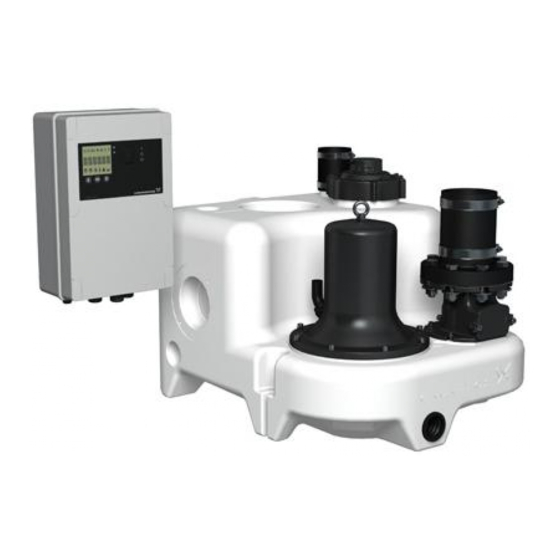
2.2 Construction The following gives a description of the components: MULTILIFT M, front and rear view MULTILIFT MD, front and rear view MULTILIFT MLD, front and rear view MULTILIFT MOG, front and rear view... - Page 12 Non-return valve with inspection cover and drain screw to lift up the valve flap. See fig. Non- return valve. MULTILIFT M, MD, MLD: Outlet adapter flange, DN 80, to pipe ∅110 with flexible connecting piece and two clamps. MULTILIFT MOG, MDG: Oval flange for outlet Collecting tank with carrying handle moulded into tank body Port, 1 1/2", for manually operated diaphragm pump...
-
Page 13: Intended Use
Code Designation Explanation 2.4 Pumped liquids MULTILIFT lifting The Grundfos MULTILIFT M, MD, MLD, MOG and Type range station MDG lifting stations are designed for the collection and pumping of the following liquids: Standard tank Tank size •... - Page 14 2.5.2 Nameplate, lifting station 2.5.3 Nameplate, motor, MULTILIFT M, MD, MLD The nameplate is located on the tank. Pos. Description Product number, Model Pos. Description Production code (year and week) Type designation Frequency Model, product number, production site, production code, year and week, counter...
- Page 15 2.5.4 Nameplate, motor, MULTILIFT MOG, MDG Pos. Description Starting capacitor Operating capacitor Insulation class Production country Pos. Description Type designation Product number Production code (year and week) Max. head Number of phases Rated input power Rated speed Rated voltage, Δ Rated voltage, Y Frequency Weight without cable...
-
Page 16: Receiving The Product
3. Receiving the product 3.3 Scope of delivery 3.3.1 MULTILIFT M, MD 3.1 Transportation Grundfos MULTILIFT M (one pump) and MD (two pumps) lifting stations are supplied complete with collecting tank, non-return valves, a sensor unit with Do not stack the product. -
Page 17: Mechanical Installation
4. Mechanical installation 3.3.3 MULTILIFT MOG, MDG Grundfos MULTILIFT MOG (one pump) and WARNING MULTILIFT MDG (two pumps) lifting stations are Explosive environment supplied complete with collecting tank, a sensor unit Death or serious personal injury with cable and one or two pumps with cable, ‐... -
Page 18: Installation Requirements
4.1 Installation requirements Related information 4.2 Installation sketches The guidelines for correct mechanical installation of lifting stations are according to EN 12056-4. • Install the lifting station in a properly lit and vented room with 60 cm free space around all parts to be serviced and operated. -
Page 19: Installation Sketches
4.2 Installation sketches Installation sketch, MULTILIFT M and MD Installation sketch, MULTILIFT MLD... - Page 20 Installation sketch, MULTILIFT MOG and MDG Pos. Accessories Product number Socket seal, DN 100 97726942 Socket seal, DN 50 98079669 Diaphragm pump, 1 1/2" 96003721 PVC isolating valve, DN 100 96615831 Cast-iron isolating valve, DN 80 M, MD, MLD: 96002011 MOG: 98085356 1 1/2"...
- Page 21 Detailed outlet pipework description for MULTILIFT MOG and MDG: Figure Description 1 1/2" complete pre-assembled outlet pipework for MULTILIFT MOG: • 1 × flexible connecting piece with 2 clamps DN 40 • 1 × hose nozzle Rp 1 1/2 / DN 40 •...
-
Page 22: Connecting The Inlet Pipe, Multilift M, Md, Mog, Mdg
4.3 Connecting the inlet pipe, MULTILIFT M, is not to be used it can easily be plugged using a standard DN 100 pipe plug fastened with three MD, MOG, MDG screws and washers. See the figure below. 1. Prepare the adjustable inlet on the back of the collecting tank. -
Page 23: Connecting The Inlet Pipe, Multilift Mld
We recommend an easy-to-handle PVC isolating valve. Minimum inlet level for MULTILIFT MLD 4.5 Installing the outlet pipe, MULTILIFT M, 4.4 Connecting the inlet pipe, MULTILIFT MD, MLD • Install an isolating valve between the non-return 1. -
Page 24: Installing The Outlet Pipe Connections, Multilift Mog, Mdg
4.6 Installing the outlet pipe connections, MULTILIFT MOG, MDG • Install a flexible connection between the pre- assembled outlet pipework and the outlet pipe. A flexible connection can be ensured if a distance of approximately 1 cm is left between the pipe ends of the connecting piece and the outlet pipe. -
Page 25: Electrical Connection
5. Electrical connection 5.1 Connecting a level sensor You can either connect an analog level sensor, such WARNING as a pressure sensor, or digital level sensors, such as Electric shock float switches. Death or serious personal injury 1. Loosen the screws and remove the front cover. ‐... - Page 26 4. Depending on the type and function of the sensor, connect the wires to the following terminals. When using an analog sensor, level switches can be used to add redundance or security by adding an extra dry-running sensor or high-level sensor or both.
-
Page 27: Wiring Connections
5.2 Wiring connections 5.2.3 Three-phase motor, LC 231 and LC 241 5.2.1 Single-phase motor, LC 231 T2 T3 T2 T3 L2 L3 EARTH PTC1 PTC2 L2 L3 L2 L3 PE PE PTC1 Three-phase connection for one pump. Single-phase connection for LC 231 5.2.2 Single-phase motor, LC 241 T2 T3 T2 T3... -
Page 28: Starting Up The Product
If the factory setting for the start level fits with the inlet level, continue with the next step. If the start level needs to be different, change it using Grundfos GO Remote. 3. Open the isolating valves in the inlet and outlet pipes. -
Page 29: Setting The Product
It is important to adjust the start level of the level 7.1 Further settings controller according to the inlet pipe. If you wish to change some settings, see the Start level for MULTILIFT M, MD, MOG, MDG: installation and operating instructions for the level between 0.17 and 0.30 m. controller. -
Page 30: Servicing The Product
Minor or moderate personal injury 5. Make a test run with clean water. ‐ Wear protective gloves. 6. In case of noise, vibration or abnormal running, contact Grundfos. CAUTION • Ball bearings Back injury Minor or moderate personal injury 1. -
Page 31: Mechanical Maintenance
2. Clean, if necessary. 8.3.2 Cleaning the non-return valve Proceed as follows 8.3 Mechanical maintenance 1. Close the isolating valves in the outlet pipe and in the inlet pipe (if fitted) or drain the outlet pipe by 8.3.1 Performing mechanical maintenance tightening the drain screw on the side of the non- return valve. - Page 32 8.3.3 Motor, MULTILIFT M, MD, MLD Check free rotation of the pump in the following way: 1. Turn off the power. 2. Unscrew the lifting eye on top of the motor. Vent holes in the pump housing and collecting tank Lifting eye 3.
-
Page 33: Performingelectrical Maintenance
If you request Grundfos to service the product, maintenance. contact Grundfos with details about the pumped liquid before returning the product for service. -
Page 34: Fault Finding
Death or serious personal injury level controller, see the installation and operating ‐ Switch off the power supply before you instructions for the level controller and Grundfos GO start any work on the product. Make Remote. sure that the power supply cannot be Related information switched on accidentally. -
Page 35: The Pump(S) Does/Do Not Run
• Recalculate the inflow parameters and compare the result with the tank volume and pump performance. • If you need a new product, contact Grundfos. 10.4 The pump(s) is/are starting/stopping too frequently even if there is no inflow Cause Remedy The level sensor fails. -
Page 36: Technical Data
For short periods up to 60 Temperature range °C (max. 5 minutes per hour) Flood conditions Max. 2 m for 7 days MULTILIFT M, MD, MLD: < 70 dB(A) according to EN 12050-1 and the Machinery Directive Sound pressure level MULTILIFT MOG, MDG: <... -
Page 37: Multilift M
11.5 MULTILIFT M Voltage Power P1/P2 Number start MULTILIFT M Duty Plug type of poles [kW] [min E/F, I M.12.1.4 1 × 230 V 1.9 / 1.4 9 / 39 1430 M.12.3.4 3 × 400 V 1.8 / 1.5 3.7 / 19... -
Page 38: Multilift Md, Mld
11.6 MULTILIFT MD, MLD Power Voltage MULTILIFT MD Number start P1/P2 Duty Plug type MULTILIFT MLD of poles [min [kW] E/F, I MD/MLD.12.1.4 1 × 230 V 1.9 / 1.4 9 / 39 1430 MD/MLD.12.3.4 3 × 400 V 1.8 / 1.5 3.7 / 19 CEE 3P+N+E, 16 A S3 -50 %,... -
Page 39: Multilift Mog, Mdg
11.7 MULTILIFT MOG, MDG Voltage Power P1/P2 Number start MULTILIFT Duty Plug type of poles [kW] [min MULTILIFT MOG (one pump) E/F, I MOG.09.1.2 1 × 230 V 6.3 / 38 2890 1.4 / 0.9 MOG.09.3.2 3 × 400 V 2.6 / 21 2860 CEE 3P+N+E, 16 A... -
Page 40: Disposing Of The Product
1. Use the public or private waste collection service. 2. If this is not possible, contact the nearest Grundfos company or service workshop. The crossed-out wheelie bin symbol on a product means that it must be disposed of separately from household waste. - Page 41 Appendix A A.1. Appendix Fig. A - Dimensional sketches - MULTILIFT M...
- Page 42 A.2. Appendix Fig. A - Dimensional sketches - MULTILIFT MD DN100 / ø110 DN100 / ø110 DN50 / ø50 DN100 / ø110 DN50 / ø50 DN50 / ø50 DN50 / ø50 DN150 / ø160 DN150 / ø160 DN70 / ø75 DN80...
- Page 43 Fig. B - Dimensional sketches - MULTILIFT MLD...
- Page 44 A.3. Appendix Fig. A - Dimensional sketch - MULTILIFT MOG DN100 / ø110 DN100 / ø110 DN50 / ø50 DN100 / ø110 DN32 DN50 / ø50 DN50 / ø50 DN150 / ø160 DN70 / ø75 DN50 / ø50...
- Page 45 Fig. B - Dimensional sketch - MULTILIFT MDG DN100 / ø110 DN50 / ø50 DN100 / ø110 DN32 DN50 / ø50 DN50 / ø50 DN150 / ø160 DN70 / ø75 DN50 / ø50...
- Page 46 Argentina China Greece Bombas GRUNDFOS de Argentina S.A. GRUNDFOS Pumps (Shanghai) Co. Ltd. GRUNDFOS Hellas A.E.B.E. Ruta Panamericana km. 37.500industin 10F The Hub, No. 33 Suhong Road 20th km. Athinon-Markopoulou Av. 1619 - Garín Pcia. de B.A. Minhang District P.O. Box 71 Tel.: +54-3327 414 444...
- Page 47 Fax: +66-2-725 8998 Fax: + 370 52 395 431 Москва, RU-109544, Russia Turkey Тел. (+7) 495 564-88-00 (495) 737-30-00 Malaysia GRUNDFOS POMPA San. ve Tic. Ltd. Факс (+7) 495 564 8811 GRUNDFOS Pumps Sdn. Bhd. Sti. E-mail grundfos.moscow@grundfos.com 7 Jalan Peguam U1/25 Gebze Organize Sanayi Bölgesi...
- Page 48 92802584 10.2022 ECM: 1343947 www.grundfos.com...
Need help?
Do you have a question about the MULTILIFT M and is the answer not in the manual?
Questions and answers