Table of Contents
Advertisement
Quick Links
Grundfos MixiMizer
Installation & Operating Instructions
Pumps Incorporating the
(MR) Mixing Reset Control
6 .
1.
Shipment
Inspection
Page 3
2.
7.
General
Page 3
3 .
8 .
Operational
Limits
Page 4
9 .
4.
Pump
Installation
Page 6
5 .
1 0 .
Installation
Requirements
Page 7
™
Mounting
Control System
Page 7
Rough-in
Wiring
Page 10
Settings
Page 13
Error Messages
& Control Response
Page 18
Quick
Reference
Page 19
Advertisement
Table of Contents

Related Manuals for Grundfos MixiMizer UP15-42


Summary of Contents for Grundfos MixiMizer UP15-42
- Page 1 Grundfos MixiMizer ™ Installation & Operating Instructions Pumps Incorporating the (MR) Mixing Reset Control Shipment Mounting Inspection Control System Page 3 Page 7 General Rough-in Wiring Page 10 Page 3 Settings Operational Limits Page 4 Page 13 Pump Error Messages &...
- Page 2 There must be at least 6 pipe diameters of straight pipe on either side of the tees in order to prevent momentum of water in the boiler and system loops from pushing flow through the injection loop. Grundfos Note 2 Note 2 Grundfos...
- Page 3 When installing and using this electrical equipment, basic safety precautions should always be followed, including the following: The installer must ensure that this control and its wiring are isolated and/or shielded from strong sources of electromagnetic noise. Conversely, this Class B digital apparatus complies with Part 15 of the FCC Rules and meets all requirements of the Canadian Interference- Causing Equipment Regulations.
-
Page 4: Shipment Inspection
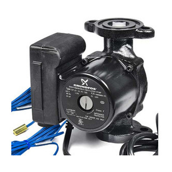
Check the contents of this package. Care should be taken to ensure the pump is NOT dropped or mis- handled; dropping will damage the pump. Grundfos MixiMizer Injection Pump Package Includes: • One Grundfos UP15-42 MixiMizer pump with integral control or one Grundfos UP43-64 MixiMizer pump with integral control. -
Page 5: Operational Limits
Grundfos MixiMizer pumps with "FC" designation are designed to pump liquids compatible with their cast iron pump housing construction. They are recom- mended for use in closed hydronic systems. Grundfos MixiMizer pumps with "BUC" and "BF" designations are designed to pump liquids compatible with their bronze pump housing construction and can be used in both open and closed systems. - Page 6 UP15-42FC/MR 115V 60 Hz MixiMizer Pump UP15-42BUC5/MR 115V 60 Hz MixiMizer Pump UP15-42BUC7/MR 115V 60 Hz MixiMizer Pump Maximum fluid temperature: 200°F (95°C) Maximum ambient: • 115°F (46°C) with control module vertical (Fig. 4a). • 115°F (46°C) with control module under pump and horizontal (Fig.
-
Page 7: Pump Installation
Pump Mounting: For Indoor Use Only Arrows on the side or bottom of the pump chamber indicate direction of flow through the pump. Grundfos Miximizer pumps can be installed in both vertical and horizontal lines. Flow direction should be from the boiler/supply loop into the system loop. -
Page 8: Installation Requirements
The pump must be installed with the motor shaft positioned horizontally. Under no circumstances should the pump be installed with the shaft vertical or where the shaft falls below the horizontal plane (Fig.4C). Recommended DO NOT Mount Motor Shaft Optional in Vertical Position Installation Requirements •... - Page 9 edition of the National Electrical Code, local codes and regulations. Install a 2” x 4” duplex electrical box to house low voltage wiring for connection to the control. Outdoor Air Temperature Sensor 070 The Outdoor Air Temperature Sensor 070 includes a 10 kW thermistor which provides an accurate measure- ment of the outdoor temperature.
- Page 10 • In order to prevent heat transmitted through the wall from affecting the sensor reading, it may be necessary to install an insulating barrier behind the enclosure. • The 070 should be mounted on a wall which best represents the heat load on the building (a northern wall for most buildings or a southern facing wall for buildings with large south facing glass areas).
-
Page 11: Rough-In Wiring
(Fig 6F & 6G) Mount the return sensor to the return piping of the boiler loop. Mount the supply sensor to supply piping of the system loop. GRUNDFOS ® LR 58223 071 Sensor... - Page 12 Com (–) terminal on the control and not to earth ground. • Run wires from the 24-30 V (ac) power source or heat demand to the electrical box for the wiring. Use a clean power source to ensure proper operation. Wiring and Testing the Outdoor Air Temperature Sensor 070 CAUTION: No wires should be connected to the...
- Page 13 wiring may be shorted, there may be moisture in the 070 or the 070 may be defective. To test for a defective 070 sensor, measure the resistance directly at the 070 sensor location. Replace the front cover of the 070 sensor enclosure. Temperature/Resistance Chart Temperature Resistance Temperature Resistance Ω...
- Page 14 Electrical Connections To The Control CAUTION: The installer should confirm that no voltage is present at any of Demand the wires. Dem / I Pull wires through the wiring Com (-) cover and install the wiring cover over the wiring Out / V chamber.
- Page 15 Dip switch settings POSITION SWITCH DEFAULT Permanent External ON position Demand Demand Permanent Demand Max system Max system ON position supply set supply feature supply set at at 140 is off Boiler return Boiler return ON position minimum set minimum feature minimum set at at 135 is off...
-
Page 16: Heating Curve
Heating Curve 3.6 3.0 WWSD Page 15... - Page 17 Page 16...
- Page 18 If the design supply water temperature is unknown, the Heating Curve dial can be set to a trial value using the typical design supply temperatures given below. Typical design supply temperatures: • Hydronic radiant floors: 100 to 130°F (38 to 54°C) •...
- Page 19 Error Messages and Control Response Whenever a fault is detected in any of the sensors, the control LEDs will flash in a specific way, to indicate the location of the problem, and the control will assume a specific operating condition. •...
-
Page 20: Quick Reference
10. Quick Reference Dip Switch Settings POSITION SWITCH DEFAULT Permanent External ON position Demand Demand Permanent Demand Max system Max system ON position supply set supply feature Permanent Demand at 140 is off Boiler return Boiler return ON position minimum set minimum feature Permanent Demand at 135... - Page 21 Made in Canada 100µ A B C D 0.35 or 0.5 VA 10µF 0.1µF 0.1µF ® 106-0 106-1 crystal Use copper wire Demand: 20 - 30 V (ac) clamp conductors only 0.1 VA Class II only Figure 10A - Control Layout Page 20...
-
Page 22: Limited Warranty
Limited Warranty Products manufactured by GRUNDFOS PUMPS CORPOR- ATION (GRUNDFOS) are warranted to the original user only to be free of defects in material and workmanship for a period of 18 months from date of installation, but not more than 24 months from date of manufacture.
Need help?
Do you have a question about the MixiMizer UP15-42 and is the answer not in the manual?
Questions and answers