Grundfos MULTILIFT MD1 Installation And Operating Instructions Manual
Hide thumbs
Also See for MULTILIFT MD1:
- Installation and operating instructions manual (48 pages) ,
- Instructions manual (29 pages)
Table of Contents
Advertisement
Quick Links
Advertisement
Table of Contents

Related Manuals for Grundfos MULTILIFT MD1


Summary of Contents for Grundfos MULTILIFT MD1
- Page 1 GRUNDFOS INSTRUCTIONS MULTILIFT MD1, MDV Installation and operating instructions...
- Page 3 MULTILIFT MD1, MDV English (GB) Installation and operating instructions ........5 Български...
- Page 4 安装和使用说明书 ..........472 MULTILIFT MD1, MDV...
-
Page 5: Table Of Contents
Applications ....9 appear in Grundfos installation and operating Pumped liquids ....9 instructions, safety instructions and service instructions. -
Page 6: Notes
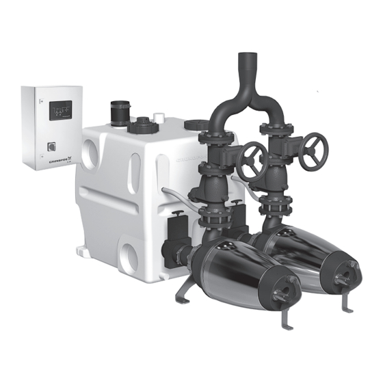
1.2 Notes 2. Product introduction The symbols and notes below may appear in 2.1 Product description Grundfos installation and operating instructions, safety instructions and service instructions. 2.1.1 Tank The gas-, odour- and pressure-tight tank is made of Observe these instructions for explosion- resistant polyethylene. - Page 7 2.1.3 Operating modes SE pumps • Continuous operation: The pump runs continuously. • Intermittent operation: Within a duty cycle of 1 minute, the pump must be stopped for 30 seconds to cool down. SL pumps • Intermittent operation: Within a duty cycle of 1 minute, the pump must be stopped for 30 seconds to cool down.
- Page 8 The inspection cover enables inspection of the tank either LC 231 or LC 241. during operation. See the documentation for the level controller for further details. Data booklet: http://net.grundfos.com/qr/i/98288126 LC 231 installation and operating instructions Dual pump unit: Pos. Description http://net.grundfos.com/qr/i/99480674...
-
Page 9: Applications
2.2 Applications 2.4 Identification The product is designed for the collection and 2.4.1 Nameplate, lifting station pumping of wastewater with no free flow to sewer The nameplate is located on the tank. level. Typically the product is installed below sewer level in cellars or basements in buildings such as: •... -
Page 10: Receiving The Product
3. Receiving the product 2.4.2 Type key Example: MD1.80.100.15.4.50D/450-2 SE 3.1 Transportation Code Designation Explanation Do not stack the product. MULTILIFT lifting Type range station Number of pumps Two pumps WARNING Falling objects Single-channel Death or serious personal injury impeller Impeller type ‐... -
Page 11: Scope Of Delivery
3.2 Scope of delivery This list applies to a standard lifting station with one tank. Additional components are included if you have ordered an additional tank. Pos. Quantity Description Specification Pressure tube With 10 m hose Flexible hose with two clamps for the DN 70 vent pipe Inlet seal... -
Page 12: Installing The Lifting Station
4. Installing the lifting station CAUTION Crushing of feet 4.1 Location Minor or moderate personal injury ‐ Wear safety shoes when moving the Install the product in a location that meets the product. following requirements: • Make sure that the location is properly lit. Ensure that weight from the inlet, outlet •... - Page 13 Example: 4.2.2 Connecting the inlet pipe • All pipe connections must be flexible to reduce resonance. • Install an isolating valve in the inlet pipe. Many installations require an inlet below the standard inlet 700 mm above the floor. You can fit a lip seal on site.
- Page 14 4.2.3 Connecting the outlet pipe 4.2.4 Connecting the vent pipe Observe the following when connecting the outlet All pipe connections must be flexible to reduce pipe: resonance. • All pipe connections must be flexible to reduce Lifting stations for black wastewater must be vented resonance.
-
Page 15: Electrical Connection
4.3 Electrical connection 4.2.5 Installing a diaphragm pump WARNING Make sure that the weight from the inlet, Electric shock outlet and vent pipes does not rest on the Death or serious personal injury tank. Long pipe sections and valves must ‐... -
Page 16: Starting Up The Product
If the factory setting for the start level fits with the inlet level, continue with the next step. If the start level needs to be different, change it using Grundfos GO Remote. 3. Open the isolating valves in the inlet and outlet pipes. -
Page 17: Setting The Product
6. Setting the product 7. Servicing the product WARNING 6.1 Further settings Electric shock If you wish to change some settings, see the Death or serious personal injury installation and operating instructions for the level ‐ Switch off the power supply before you controller. -
Page 18: Maintenance Schedule
7.1 Maintenance schedule 7.2.2 Cleaning the pressure tube and hose 1. Set the selector switches to OFF. 7.1.1 Maintenance intervals 2. Close all inlet valves. According to EN 12056-4, the lifting station must be checked at the following intervals to ensure safe and 3. -
Page 19: Performingelectrical Maintenance
Replace the 9 V battery, if fitted, in connection been used for a liquid which is injurious to health or with the annual service. toxic. If you request Grundfos to service the product, contact Grundfos with details about the pumped liquid The above list is not complete. The before returning the product for service. -
Page 20: Returning The Product For Service
10.1 Warning and alarm codes on the display of the level controller For information about causes and remedies for warning and alarm codes shown on the display on the level controller, see the installation and operating instructions for the level controller and Grundfos GO Remote. -
Page 21: The Pump(S) Does/Do Not Run
• Recalculate the inflow parameters and compare the result with the tank volume and pump performance. • If you need a new product, contact Grundfos. 10.4 The pump(s) is/are starting/stopping too frequently even if there is no inflow Cause Remedy The level sensor fails. -
Page 22: Technical Data
1. Use the public or private waste collection service. Controller 2. If this is not possible, contact the nearest Ambient temperature 0-40 Grundfos company or service workshop. during operation [°C] The crossed-out wheelie bin Pump symbol on a product means... - Page 23 Argentina China Greece Bombas GRUNDFOS de Argentina S.A. GRUNDFOS Pumps (Shanghai) Co. Ltd. GRUNDFOS Hellas A.E.B.E. Ruta Panamericana km. 37.500industin 10F The Hub, No. 33 Suhong Road 20th km. Athinon-Markopoulou Av. 1619 - Garín Pcia. de B.A. Minhang District P.O. Box 71 Tel.: +54-3327 414 444...
- Page 24 Fax: +66-2-725 8998 Fax: + 370 52 395 431 Москва, RU-109544, Russia Turkey Тел. (+7) 495 564-88-00 (495) 737-30-00 Malaysia GRUNDFOS POMPA San. ve Tic. Ltd. Факс (+7) 495 564 8811 GRUNDFOS Pumps Sdn. Bhd. Sti. E-mail grundfos.moscow@grundfos.com 7 Jalan Peguam U1/25 Gebze Organize Sanayi Bölgesi...
- Page 25 92862079 10.2022 ECM: 1343947 www.grundfos.com...
Need help?
Do you have a question about the MULTILIFT MD1 and is the answer not in the manual?
Questions and answers