
Subscribe to Our Youtube Channel
Related Manuals for Johnson Controls York YD


Summary of Contents for Johnson Controls York YD
- Page 1 Model YD Mod D with OptiView Control Center Centrifugal Liquid Chillers Operations Manual Form Number: 160.79-O3 (921) Issue Date: 2021-09-16 Supersedes: 160.79-O3 (1020)
- Page 2 Model YD Mod D with OptiView Control Center...
-
Page 3: Table Of Contents
Contents General safety guidelines..........................5 C o n t e n t s Safety symbols............................5 Changeability of this document......................6 Associated literature..........................6 Conditioned based maintenance......................7 Nomenclature............................8 Description of system and fundamentals of operation................9 System operation description......................9 Compressor starting........................... 10 Compressor shutdown........................14 OptiView Control Center..........................23 OptiView control center in detail....................... - Page 4 Model YD Mod D with OptiView Control Center...
-
Page 5: General Safety Guidelines
General safety guidelines Important: Read before proceeding. This equipment is a relatively complicated apparatus. During rigging, installation, operation, maintenance, or service, individuals may be exposed to certain components or conditions including, but not limited to: heavy objects, refrigerants, materials under pressure, rotating components, and both high and low voltage. -
Page 6: Changeability Of This Document
All wiring must be in accordance with Johnson Controls’ published specifications and must be performed only by a qualified electrician. Johnson Controls will NOT be responsible for damage/problems resulting from improper connections to the controls or application of improper control signals. -
Page 7: Conditioned Based Maintenance
Traditional chiller maintenance is based upon assumed and generalized conditions. In lieu of the traditional maintenance program, a Johnson Controls YORK Conditioned Based Maintenance (CBM) program can be substituted. This CBM service plan is built around the specific needs for the chiller, operating conditions, and annualized impact realized by the chiller. -
Page 8: Nomenclature
Nomenclature Model YD Mod D with OptiView Control Center... -
Page 9: Description Of System And Fundamentals Of Operation
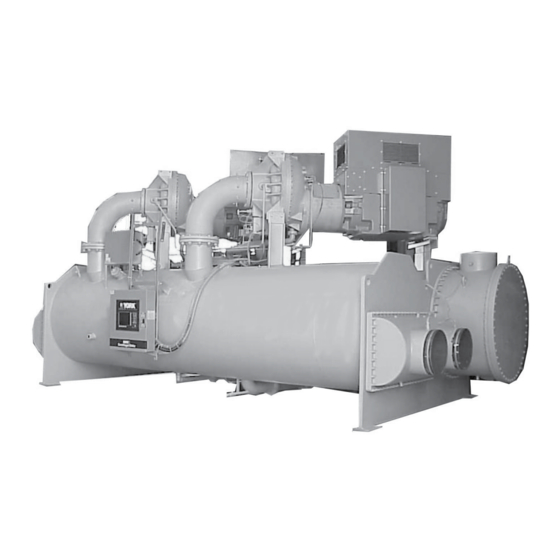
Description of system and fundamentals of operation System operation description The following is a high-level description of the chiller control. It describes the overall operation. Control Center components, chiller components and programmable setpoints are referenced. See Figure 2 to view the chiller operation flowchart. The YD dual compressor chiller consists of one evaporator, one condenser, two oil pumps and two compressors. -
Page 10: Compressor Starting
You can performs a lockout on a compressor to prevent it from running. Only one compressor at a time can be locked out. Two CM-2 current boards, one for each compressor motor, provides motor Overload and Power Fault protection for units with E-M starters. Units with SSS or VSDs have motor Overload and Power Fault protection built in to the starter. - Page 11 Discharge #X – Valve Not Opened appears. Upon entering prelube, the refrigerant level control raise (close) output to the variable orifice is energized for the duration of the Valve Preset Time setpoint (0 to 100 seconds). After this pre-positioning, the valve is held in this position for the first 3 minutes of compressor operation.
- Page 12 has opened, the Condenser Refrigerant Control ramp-up period begins as described in Condenser refrigerant level control – lag start. While both compressors are running, the variable geometry diffusers are modulated according to the stall activity and pre-rotation vanes position. There is no VGD response to surge activity.
- Page 13 while starting the Lag compressor. The Override Time Remaining displays the time remaining in the Valve Preset mode or the time remaining in the Lag Start mode. In the first case, it is the time remaining in the Valve Preset Timer plus the time remaining of the first 3 minutes of lead compressor run time.
-
Page 14: Compressor Shutdown
• Proximity Probe – Low Supply Voltage • Discharge [#1/#2] – Low Temperature • Discharge [#1/#2] – High Temperature • Oil Pump [#1/#2] - Differential Pressure Calibration • Oil Pump [#1/#2] – Pressure Transducer Out of Range • Thrust Bearing [#1/#2] – Proximity Probe Clearance •... - Page 15 • “Control panel – Schedule” If any faults other than those listed above occur during a soft shutdown, the soft shutdown is aborted, the run signal to the compressor motor starter is de-energized and the compressor or compressors immediately enter Coastdown. If an operator initiates a Local Stop with the Keypad Rocker Switch or any fault occurs other than those listed immediately above, a Fault Shutdown is performed on all running compressors.
- Page 16 Chiller operation flow chart Figure 2: Chiller operation flow chart Model YD Mod D with OptiView Control Center...
- Page 17 Figure 2: Chiller operation flow chart Model YD Mod D with OptiView Control Center...
- Page 18 Figure 2: Chiller operation flow chart Model YD Mod D with OptiView Control Center...
- Page 19 Figure 2: Chiller operation flow chart Model YD Mod D with OptiView Control Center...
- Page 20 Figure 2: Chiller operation flow chart Model YD Mod D with OptiView Control Center...
- Page 21 Figure 2: Chiller operation flow chart Model YD Mod D with OptiView Control Center...
- Page 22 Figure 2: Chiller operation flow chart Model YD Mod D with OptiView Control Center...
-
Page 23: Optiview Control Center
OptiView Control Center The YORK OptiView™ Control Center is a microprocessor based control system for R-134a centrifugal chillers. It controls the leaving chilled liquid temperature through pre-rotation vane controls and can limit motor current through control of the pre-rotation vanes. The panel comes configured with a full screen LCD Graphic Display mounted in the middle of a keypad interface. -
Page 24: Optiview Control Center In Detail
Y.OPT.11.xx.yzz: • Y – Commercial chiller • OPT - Used on Microboard 031-03630-007 • 11 – YD chiller • xx - controls revision level (00, 01, etc.) • y – language package (0=English only, 1=NEMA, 2=CE, 3=NEMA/CE ) • zz – language package revision level (00, 01, etc.) OptiView control center in detail The OptiView™... -
Page 25: Overview Of Interface
The Start/Stop control is operated using a three-position rocker switch. When toggled all the way to the right, it is in the STOP/RESET position. When in the middle position, this is the RUN state. When toggled to the left-most position, it is in the START state. Each state is described in detail as follows: STOP / RESET When in this position, the chiller does not run under any condition. - Page 26 LOGIN button or utilize the CHANGE SETPOINTS key described below. At this point, the user will be prompted to enter a User ID and the corresponding Password. By default, the User ID is zero (0). In order to gain standard OPERATOR level access, the Password would be entered as 9 6 7 5, using the numeric keypad.
- Page 27 Navigation In order to maximize the amount of values that the panel can display to the user, and in order to place those values in context, multiple screens have been designed to describe the chiller operation. In order to move from one screen to the next, navigation keys have been defined. These keys allow the user to either move “forward”...
-
Page 28: Analog Input Ranges
the default language. If a language other than English is being displayed, an English-only speaking person should navigate to the USER Screen using the preceding Navigation chart and select English per the USER Screen instructions in this book. Analog input ranges The following table indicates the valid display range for each of the analog input values. -
Page 29: Slot Numbers
Slot numbers Table 2: Slot numbers Slot number Description Evaporator 1792 Leaving Chilled Liquid Temperature 1793 Temperature Differential 1794 Chilled Liquid Flow Switch 1795 Chilled Liquid Pump 1807 Return Chilled Liquid Temperature 1808 Evaporator Pressure 1809 Evaporator Saturation Temperature 1810 Small Temperature Difference 1812 Evaporator Refrigerant Temperature... - Page 30 Table 2: Slot numbers Slot number Description Surge - single compressor 8236 Surge Detected 8238 Total Surge Count Surge - dual compressor 18958 Surge Detected 18960 Total Surge Count Hot gas 8231 Valve Position Oil sump 1537 Oil Sump Temperature 1542 Oil Heater 18497...
- Page 31 Table 2: Slot numbers Slot number Description 184562826 VSD 1 Phase C Output Current (RMS) 2982 VSD 1 DC Bus Voltage AU 2983 VSD 1 DC Bus Voltage AL 2984 VSD 1 DC Bus Voltage BU 2985 VSD 1 DC Bus Voltage BL 2986 VSD 1 DC Bus Voltage CU 2987...
- Page 32 Table 2: Slot numbers Slot number Description 17680 Biased Anti-Surge Minimum Frequency 18240 Lead Surge Frequency 18241 Lag Surge Frequency 17681 Active Anti-Surge Minimum Frequency 17682 Lead Active Minimum PRV Position 17777 Evaporator Pressure Override Threshold 17776 Condenser Pressure Override Threshold 18251 Lead Motor Current Override Threshold Model YD Mod D with OptiView Control Center...
-
Page 33: Display Messages
Display messages The status bar of the display contains a status line and, beneath it a details line. The status line contains a message describing the operating state of the chiller; whether it is stopped, running, starting or shutting down. The details line displays Warning, Cycling, Safety, Start Inhibit and other messages that provide further details of the status bar messages. -
Page 34: Run Messages
Table 3: Status messages Message Description System Run The chiller is running under the condition described in the Details Line of the Status Bar. The chiller has shut down and the Post-run lubrication is being performed. System Coastdown The chiller is prevented from being started due to the reason displayed on the Details Line of System Start Inhibit the Status bar. -
Page 35: Start Inhibit Messages
Start inhibit messages Table 5: Start inhibit messages Message Description Discharge Valve #1 - The chiller (both compressors) is inhibited from starting because compressor #1 discharge valve is not closed. This start inhibit is released when the valve has fully closed. Open The chiller (both compressors) is inhibited from starting because compressor #2 discharge Discharge Valve #2 -... -
Page 36: Warning Messages
Warning messages Table 6: Warning messages Message Description Warning – Condenser Or The evaporator pressure transducer is indicating a higher pressure than the condenser pressure transducer after the chiller has been running for 10 minutes. This is indicative Evaporator XDCR Error of a condenser or evaporator transducer failure. - Page 37 Table 6: Warning messages Message Description Warning – Head Pressure Displayed when starting the lag compressor while a high head condition exists. A high head condition exists when the actual Delta P/P is greater than the High Head DP/P Limit –...
- Page 38 Table 6: Warning messages Message Description Warning – Surge This warning applies to single compressor operation only and only if the Surge Protection Extended Run setpoint is enabled. The chiller is operating in a Surge Protection – Excess Surge Limit Protection Extended Run period because the Surge Window Count has exceeded the Count Limit setpoint during single compressor operation.
-
Page 39: Routine Shutdown Messages
Table 6: Warning messages Message Description Warning – Motor Bearing The Operating Hours Since Last Motor Lubrication has exceeded 1200 hours (the greater of either Motor #1 Operating Hours or Motor #2 Operating Hours is used Lube Required for this calculation). This warning replaces Warning – Motor Bearing Lube Suggested above. -
Page 40: Cycling Shutdown Messages
Cycling shutdown messages Table 8: Cycling shutdown messages Message Description Multiunit Cycling – The multiunit cycling contacts connected to I/O Board TB4-9, have opened to initiate a cycling shutdown on the chiller (both compressors). If the chiller is running when this occurs, Contacts Open the pre-rotation vanes on the running compressors are driven fully closed prior to shutting down the chiller. - Page 41 Table 8: Cycling shutdown messages Message Description Motor Controller #2 – The chiller (both compressors 0 shutdown because compressor #2 motor current has decreased to < 10% FLA for 25 continuous seconds while it was running. This could be caused Loss Of Current by the starter de-energizing or a defect in the motor current detection circuitry to the control center.
- Page 42 Table 8: Cycling shutdown messages Message Description Oil Pump #2 – Drive The oil pump variable speed drive for compressor 2 has shutdown the chiller (both compressors). It initiates this shutdown by opening its status contacts connected to the I/ Contacts Open O Board TB3-71.
- Page 43 Table 8: Cycling shutdown messages Message Description Control Panel – Power A control power failure has occurred. If the power failure occurred while the chiller was running, it will automatically restart when power is restored. However, if the power failure Failure duration was <...
-
Page 44: Safety Shutdown Messages
Safety shutdown messages Table 9: Safety shutdown messages Message Description Evaporator – Low The evaporator pressure, as sensed by the evaporator transducer, has decreased to the safety shutdown threshold. For water cooling applications, the safety shutdown threshold Pressure is a fixed value for the respective refrigerant. For brine cooling applications, the safety shutdown threshold varies according to the concentration of the brine solution. - Page 45 Table 9: Safety shutdown messages Message Description DISCHARGE #1 – HIGH The contacts of the electro-mechanical high pressure switch (HP1, located in the discharge line of compressor #1) have opened because it detected a pressure >180.0 psig. The contacts PRESSURE CONTACTS OPEN will automatically close when the discharge pressure decreases to <...
- Page 46 Table 9: Safety shutdown messages Message Description DISCHARGE #1 – VALVE The chiller (both compressors) has shutdown because compressor #1 Discharge Valve did not fully open (as indicated by the closure of the valve opened end switch) within 40 seconds NOT OPENED of receiving the open command.
- Page 47 Table 9: Safety shutdown messages Message Description OIL PUMP #1 – LOW The chiller (both compressors) has been shutdown because the differential oil pressure, as sensed by compressor #1 Pump transducer and the Sump transducer, decreased to DIFFERENTIAL PRESSURE <15.0 PSID while compressor #1 was running or went below 25.0 PSID during the last 5 seconds of compressor #1 Prelube.
- Page 48 Table 9: Safety shutdown messages Message Description OIL PUMP #2 – SETPOINT The chiller (both compressors) has shutdown because compressor #2 differential oil pressure, as sensed by compressor #2 Pump transducer and the Sump transducer, failed to NOT ACHIEVED meet the following requirements: •...
- Page 49 Table 9: Safety shutdown messages Message Description THRUST BEARING #2 The chiller (both compressors) has shutdown because the clearance between Compressor #2 high speed thrust collar and the tip of the proximity Probe has increased > +10 mils – PROXIMITY PROBE CLEARANCE (instantaneous) or decreased >...
- Page 50 Table 9: Safety shutdown messages Message Description THRUST BEARING #2 – The chiller (both compressors) has shutdown because the clearance between compressor #2 high speed thrust collar and the tip of the proximity Probe has decreased to <17 mils. The PROXIMITY PROBE OUT OF RANGE chiller cannot be started until the special reset procedure is performed as referenced in the...
-
Page 51: Printers
Printers Printing overview A laptop computer can be connected to the Control Center’s Microboard to capture the following reports. The screen from which each report can be generated is listed in parenthesis. • Status - Present system parameters (Printer, Home). •... -
Page 52: Downloading System Prints To A Laptop
Downloading system prints to a laptop About this task: Downloading system histories to a file is another useful method to capture system operating conditions. The following instructions are used to establish communication between the OptiView Control Panel and a laptop computer running any Terminal Emulation program such as HyperTerminal, TeraTerm, or PuTTy. - Page 53 The connector on the PC has Male pins, therefore the mating cable needs to terminate in a DB25/F (Female pin) connector. Table 13: RS-232 pin assignments - DB9 PC signal set (most laptops) Description Description Received line Signal Detector (Data Carrier Pin 2 Received Data Pin 1...
- Page 54 Figure 7: Sample printout (status) Model YD Mod D with OptiView Control Center...
- Page 55 Figure 7: Sample printout (status) Model YD Mod D with OptiView Control Center...
- Page 56 Figure 8: Sample printout (setpoints) Model YD Mod D with OptiView Control Center...
- Page 57 Figure 8: Sample printout (setpoints) Model YD Mod D with OptiView Control Center...
- Page 58 Figure 9: Sample printout (schedule) Model YD Mod D with OptiView Control Center...
- Page 59 Figure 10: Sample printout (sales order) Model YD Mod D with OptiView Control Center...
- Page 60 Figure 11: Sample printout (history) Model YD Mod D with OptiView Control Center...
- Page 61 Figure 11: Sample printout (history) Model YD Mod D with OptiView Control Center...
- Page 62 Figure 12: Sample printout (security log report) Figure 13: Sample printout (trend data new or existing points) Model YD Mod D with OptiView Control Center...
- Page 63 Figure 14: Sample printout (custom screen report) Model YD Mod D with OptiView Control Center...
-
Page 64: Unit Conversion
To convert a temperature range (i.e., a range of 10°F) from Fahrenheit to Celsius, multiply by 5/9 or 0.5556. Example: 10.0°F range x 0.5556 = 5.6°C range. © 2021 Johnson Controls. 5000 Renaissance Drive, New Freedom, York, PA 17349, USA. Subject to change without notice. All rights reserved.
Need help?
Do you have a question about the York YD and is the answer not in the manual?
Questions and answers