Table of Contents
Advertisement
Quick Links
Advertisement
Table of Contents

Related Manuals for Johnson Controls York YD


Summary of Contents for Johnson Controls York YD
- Page 1 CENTRIFUGAL LIQUID CHILLERS INSTALLATION INSTRUCTION Supersedes: 160.69-N2 (912) Form 160.69-N2 (715) MODEL YD (STYLE B) R-134A (COOLING ONLY) WITH OPTIVIEW™ CONTROL CENTER AND ELECTRO-MECHANICAL STARTER LD08634 R-134A Issue Date: July 31, 2015...
- Page 2 All wiring must be in accor- dance with Johnson Controls’ published specifications and must be performed only by a qualified electrician. Johnson Controls will NOT be responsible for damage/problems resulting from improper connections to the controls or application of improper control signals.
- Page 3 FORM 160.69-N2 ISSUE DATE: 7/31/2015 CHANGEABILITY OF THIS DOCUMENT In complying with Johnson Controls’ policy for con- regarding the applicability of these documents, rig- tinuous product improvement, the information con- ging, lifting, and operating/service personnel should tained in this document is subject to change without verify whether the equipment has been modified and notice.
- Page 4 HB, HC, HD, H2, H3, H4 GB, GC, GD, G2, G3, G4 FB, FC, FD, F2, F3, F4 EB, EC, ED, E2, E3, E4 DB, DC, DD, D2, D3, D4 CB, CC, CD, C2, C3, C4 BB, BC, BD, B2, B3, B4 MODEL JOHNSON CONTROLS...
-
Page 5: Table Of Contents
Control Wiring ..............................23 Power Wiring ..............................23 Oil Pump – 3 Phase Starter ........................23 YD Motors (Electro-Mechanical Starter) ....................23 Insulation ................................ 23 Installation Check – Request For Start-Up Service ..................24 Compressor Motor Field Connection Diagram ....................24 JOHNSON CONTROLS... - Page 6 TABLE 1 - Evaporator – Condenser Shell Codes ....................16 TABLE 2 - Approximate Unit Weight Including Motor and Compact Water Boxes ..........17 TABLE 3 - Marine Waterbox Weight ........................17 TABLE 4 - Approximate Unit Motor Weights ......................18 TABLE 5 - Motor Connections ..........................24 JOHNSON CONTROLS...
-
Page 7: Section 1 - Introduction
Form 2 – Factory Assembled Unit, complete with with all units that are to be field assembled. motors (refrigerant and oil charges shipped separately). The services of a Johnson Controls representative will 1. The motor/compressor assemblies mounted, with be furnished to check the installation, supervise the all necessary interconnecting piping assembled. -
Page 8: Inspection - Damage - Shortage
(2 to 3 psig) (14-21 kPa). diately for their inspection. Miscellaneous packaging of control center, tubing, Johnson Controls will not be responsible water temperature controls, wiring, oil isolators, solid for any damage in shipment or at job site state starter (option), etc.;... -
Page 9: Chiller Data Plate
The lengthwise rigging bar should be longer than the chiller tube length, and must have counter or clevis ad- justments to allow for center of gravity adjustments. Chain spreaders should be used to avoid contact with drive motors or other chiller parts. JOHNSON CONTROLS... -
Page 10: Figure 1 - Rigging
FORM 160.69-N2 SECTION 1 - INTRODUCTION ISSUE DATE: 7/31/2015 LD09014a FIGURE 1 - RIGGING JOHNSON CONTROLS... -
Page 11: Neoprene Isolators
C/C and D/D - Up to 225,000 lbs. (102,060 Kgs) E/E, F/F, G/G, H/H and K/K - Up to 280,000 lbs (127,005 Kgs) LD19590a LD19589a Mounting 3/8” Bracket (10) 3/4” (19) LD19571a DETAIL A FIGURE 2 - NEOPRENE ISOLATORS JOHNSON CONTROLS... -
Page 12: Figure 3 - Neoprene Isolators
Up to 280,000 lbs (127,005 Kgs) 14' 8" (4471) 11" (279) 12 (305) Up to 280,000 lbs (127,005 Kgs) 14' 8" (4471) 11" (279) 12 (305) Approx weight including motor and 150# compact water boxes. FIGURE 3 - NEOPRENE ISOLATORS JOHNSON CONTROLS... -
Page 13: Spring Isolators
G-G and H-H - Up to 240,000 lbs (108,862 Kgs) SHELL SHEET 1 / 4 " ( 3 8 SCREW ADJUSTING BOLT 4-SPRING ISOLATORS LD19592 K-K - Up to 250,000 lbs (113,400 Kgs) K-K - Up to 320,000 lbs (145,150 Kgs) FIGURE 4 - SPRING ISOLATORS JOHNSON CONTROLS... -
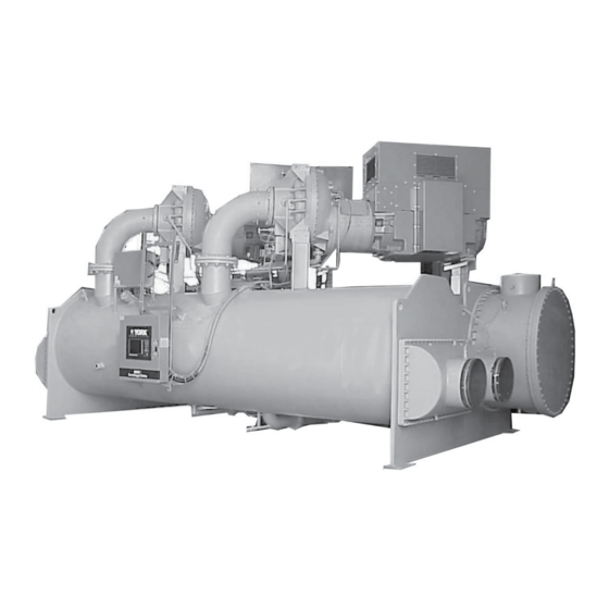
Page 14: Figure 5 - Model Yd Chiller
FORM 160.69-N2 SECTION 1 - INTRODUCTION ISSUE DATE: 7/31/2015 MOTOR #1 MOTOR #2 COMPRESSOR #2 COMPRESSOR #1 OPTIVIEW™ EVAPORATOR CONTROL CONDENSER CENTER LD08634 FIGURE 5 - MODEL YD CHILLER JOHNSON CONTROLS... -
Page 15: Figure 6 - Dimensions - J Compressor Units
FORM 160.69-N2 SECTION 1 - INTRODUCTION ISSUE DATE: 7/31/2015 CONDENSER EVAPORATOR COMPRESSORS MOTORS 9" LD09013 SHIPPING WIDTH FLOOR LINE LD09012 FIGURE 6 - DIMENSIONS – J COMPRESSOR UNITS JOHNSON CONTROLS... -
Page 16: Unit Dimensions
1-3/4" length for flanges connections. Spring Isolators 1" Deflection 1" 4. To determine overall height, add dimension "M" for the appropriate isolator type. Direct Mount 3/4" 5. Use of motors with motor hoods may increase overall unit dimensions. JOHNSON CONTROLS... -
Page 17: Unit Weights
(3,559) (6,378) 8,424 4,644 8,764 14,920 7,846 14,063 (3,821) (2,106) (3,975) (6,767) (3,559) (6,378) 10,332 5,521 10,371 17,704 9,161 16,412 (4,686) (2,504) (4,703) (8,030) (4,155) (7,444) 10,332 5,521 10,371 17,704 9,161 16,412 (4,686) (2,504) (4,703) (8,030) (4,155) (7,444) JOHNSON CONTROLS... -
Page 18: Table 4 - Approximate Unit Motor Weights
7,300 3,318 1400 7,500 3,409 1500 7,500 3,409 1500 7,500 3,409 1650 7,900 3,591 1750 7,500 3,409 1750 11,250 5,114 2000 8,500 3,864 2000 11,750 5,341 2250 11,750 5,341 1750 12,750 5,795 2500 12,750 5,795 2000 13,250 6,023 JOHNSON CONTROLS... -
Page 19: Section 2 - Installation
Johnson Controls representative. the tapped hole in the top of the isolator leveling bolts. Then the unit can be lowered onto the floor. -
Page 20: Evaporator And Condenser Water Piping
All water piping must be cleaned or flushed before being connected to the chiller pumps, or other equipment. Permanent strainers (supplied by others) are required JOHNSON CONTROLS... -
Page 21: Figure 7 - Schematic Of A Typical Piping Arrangement
STRAIN ON RELIEF PIPING DISASSEMBLY FLEXIBLE CONNECTOR CONDENSATION TRAP CONDENSER DUAL RELIEF SEE NOTE VALVES COOLER NOTE: SHELLS MAY BE FURNISHED WITH ONE OR TWO RELIEF VALVES, DEPENDING ON SHELL SIZE. FIGURE 8 - TYPICAL REFRIGERANT VENT PIPING LD03863a JOHNSON CONTROLS... -
Page 22: Stop Valves
Johnson Controls representative: (1) the lubricant tory wired to the OptiView control panel. These solid- piping to oil sump and oil evaporator and system oil state flow sensors have a small internal heating ele- return connections using material furnished. -
Page 23: Control Wiring
Johnson Controls representative. DO NOT cut wires to final length or make final connections to motor terminals or starter power input terminals until ap- proved by the Johnson Controls repre- sentative. JOHNSON CONTROLS... -
Page 24: Installation Check - Request For Start-Up Service
1. Requires passing motor lead thru current transformer (CT) once in the contract price, can be scheduled. Notification to before connecting to power supply. the Johnson Controls office should be by means of In- 2. Requires passing motor lead thru CT twice before connecting to power supply. - Page 25 FORM 160.69-N2 ISSUE DATE: 7/31/2015 NOTES JOHNSON CONTROLS...
- Page 26 P.O. Box 1592, York, Pennsylvania USA 17405-1592 800-861-1001 Subject to change without notice. Printed in USA Copyright © by Johnson Controls 2015 www.johnsoncontrols.com ALL RIGHTS RESERVED Form 160.69-N2 (715) Issue Date: July 31, 2015 Supersedes: 160.69-N2 (912)
Need help?
Do you have a question about the York YD and is the answer not in the manual?
Questions and answers