
Related Manuals for Keywish Hummer-Bot-2.0


Summary of Contents for Keywish Hummer-Bot-2.0
- Page 1 Hummer-Bot-2.0 Instruction Manual V.2.3 Github https://github.com/keywish/keywish-hummer-bot-v2.0...
- Page 2 Revised Version Of History Date Version Description Author 2017/9/16 V.1.0 Create Baron.li 2017/9/23 V.1.1 modify Ken.chen 2017/10/18 V.1.2 Review Ken.chen 2017/11/15 V.1.3 Review Zach.zhou 2017/12/8 V.1.4 Review Baron.li 2018/3/11 V.1.5 Modifyir/blutooth module Ken.chen 2018/4/20 V.1.6 Add device instructions Baron.li 2018/5/3 V.1.7 Add installation details picture Baron.li...
-
Page 3: Table Of Contents
3.1.2 Wheel and drive module installation ..................16 3.1.3 Tracking module installation ....................18 3.1.4 Lower acrylic plate copper column installation and motor wiring ......... 20 3.1.5 Keywish Uno R3 board installation ..................22 3.1.6 Battery box installation ......................23 3.1.7 Servo installation ........................24 3.1.8 Infrared obstacle avoidance module installation .............. -
Page 4: Chapter1 Introduction
This manual is very suitable for students and electronic enthusiasts to learn, all course videos will be ,please real-time synchronization synchronized to https://github.com/keywish/keywish-hummer-bot-v2.0 of the latest information 1.2 Product Introduction "Hummer-Bot" is a multifunctional car based on the Arduino UNO and L298N motor. Compared with the traditional car, "Hummer-Bot"... - Page 5 ◆ Ultrasonic obstacle avoidance ◆ Four DC motor drive ◆ Two 3000mZh, 3.7V rechargeable lithium battery with longer endurance ◆ Remaining capacity of battery real-time detection ◆ Infrared remote control ◆ Bluetooth app control ◆ PS2 handle control (optional) Product Device List...
-
Page 6: Chapter2 Preparations
Chapter2 Preparations About Arduino uno r3 ◆ In "Aurora-Racing", we used the Arduino uno r3 as the main control board, which has 14 digital input/output pins (6 of which can be used as PWM output), 6 analog inputs, and a 16 MHz ceramic resonator, 1 USB connection, 1 power socket, 1 ICSP head and 1 reset button. -
Page 7: Development Environment Arduino Ide
2.1 Development environment Arduino IDE 2.1.1 Install the IDE AduinoIDE is an open source software and hardware tool written by open source software such as Java, Processing, and avr-gcc. It is an integrated development environment that runs on a computer. It can write and transfer programs to the board. - Page 8 the installation is complete, click "arduino.exe" again to enter the IDE programming interface. Figure 2.1.2 Arduino IDE Installation Package Figure 2.1.3 Extracted files When finish the installation of the IDE,connect to the Arduino motherboard,click“My Computer” →“Properties”→“Device Manager”→ “Viewing Ports (COM and LTP)”,If you can see as the Figure 2.1.4 Figure 2.1.4 Driver installation success interface that indicates the driver has been installed successfully,At this time we open the IDE, select the...
- Page 9 Figure 2.1.5 Driver is not successfully installed interface Notice: 1)If you connect the controller board to the computer, the computer does not respond. Right-click "My Computer" and select Open Device Manager then find viewing port (com & lpt). If there is no com or lpt, or only an unknown device, there is a problem with the controller board or the USB cable.
- Page 10 Figure 2.1.6 Updated Driver Interface 2)Next, select the "Browse my computer for driver software" option. Figure 2.1.7 Driver Update Selection Screen...
- Page 11 3)Finally select the driver file named "FTDI USB Drivers" located in the "Drivers" folder of the Arduino software download. Figure 2.1.8 Driver file selection interface 4)If you have already installed, the following figure will automatically inform you that the driver was successful.
- Page 12 Figure 2.1.9 Driver Installation Successful Interface At this time, we return to the "Device Manager" interface, the computer has successfully identified Arduino, as shown in the below Figure 2.1.10 .then open the Arduino compilation environment, you can open the Arduino trip. Figure 2.1.10 Driver Success Recognition Interface...
- Page 13 Notice In Win10 system, some Arduino are connected to the computer (non-genuine chips are difficult to identify), the system will automatically download the corresponding driver, so you can not install the driver yourself, but in the Win7 system, you have to do it yourself. In addition, we can see that the USB serial port is identified as COM15 in the above figure, but it may be different with different computer, you may be COM4, COM5, etc., but USB-SERIAL CH340, this must be the same.
- Page 14 Figure 2.1.12 Arduino IDE Interface 2.There are 5 menus on the menu bar, but we mainly introduce File and Tools. Click File, the interface as shown in Figure 2.1.13 will be displayed, you can see the Examples and Preference options. The Examples are some of the Arduino's own programs, these are compiled without errors, the normal use of the program, a great help for beginners.
- Page 15 Figure 2.1.14 Tools interface Figure 2.1.15 USB serial port selection So far, we have basically completed all the work. The next step is actual experiments. Open any program in Examples. First compile the program. If it is compiled correctly, it can be directly downloaded to the development board and the corresponding device of the connection number.
-
Page 16: Chapter3 Experiments
Chapter3 Experiments 3.1 Assembly of the Car 3.1.1 Motor installation Step1: You need to install the motor mount. Figure 3.1.1 Schematic diagram of motor mounting Note: You need to use the screw to pass through the front hole of the motor, the motor holder corresponds to the opposite position and use the nut to fix the motor holder. - Page 17 Step2: You need to solder the wire to the motor. Figure 3.1.3 Effect diagram of solder the wire Step3: You need to fix the wire with a cable tie. Figure 3.1.4 Effect diagram of fixing the wire...
- Page 18 Step4: You need to install motors. Figure 3.1.5 Schematic diagram of motor installation Figure 3.1.6 Effect diagram of motor installation...
-
Page 19: Wheel And Drive Module Installation
3.1.2 Wheel and drive module installation Figure 3.1.7 Schematic diagram of wheel installation Figure 3.1.8 Effect diagram of wheel installation... - Page 20 Step2:You need to install motor driver module. Figure 3.1.9 Shematic diagram of fixing motor driver board Figure 3.1.10 Shematic diagram of fixing motor driver board...
-
Page 21: Tracking Module Installation
3.1.3 Tracking module installation Figure 3.1.11 Shematic diagram of copper column of tracking moduble installation Figure 3.1.12 Effect diagram of copper column of tracking moduble installation... - Page 22 Figure 3.1.13 Shematic diagram of tracking moduble installation Note: You need to screw the M3 nut to the bottom of the M3*10 screw and install it. Figure 3.1.14 Effect diagram of copper column of tracking moduble installation...
-
Page 23: Lower Acrylic Plate Copper Column Installation And Motor Wiring
3.1.4 Lower acrylic plate copper column installation and motor wiring Figure 3.1.15 Shematic diagram of motor wiring Note: You need to insert the 4Pin DuPont cable into the motor drive board input. Figure 3.1.16 Effect diagram of motor wiring... - Page 24 Figure 3.1.17 Shematic diagram of copper column installstion Figure 3.1.18 Effect diagram of copper column installstion...
-
Page 25: Keywish Uno R3 Board Installation
3.1.5 Keywish Uno R3 board installation Figure 3.1.19 Shematic diagram of Keywish Uno R3 board installation Figure 3.1.20 Effect diagram of Keywish Uno R3 board installation... -
Page 26: Battery Box Installation
3.1.6 Battery box installation Figure 3.1.21 Shematic diagram of battery box installation Figure 3.1.22 Effect diagram of battery box installation... -
Page 27: Servo Installation
3.1.7 Servo installation Figure 3.1.23 Shematic diagram of servo installation Figure 3.1.24 Effect diagram of servo installation In order to reduce the angle adjustment of the servo, we need to adjust the servo to 90 degrees. First, we should (Lesson\ModuleDemo\ServoTest\ServoTest.ino) Download it to the control panel, and the three wires of the steering gear are the signal wire (orange), power wire (red), and ground wire (brown), and then connect the signal wire of the steering gear (orange) to port 13 of Arduino, and install the rudder propeller without fixing screws, as shown in figure 3.1.7.1. - Page 28 Figure. 3.1.7.1 steering gear debugging connection diagram After burning the program to the UNO board, do not unplug the USB cable and plug the battery plug into the UNO board to power it, then open the serial port monitor for the Arduino IED, as shown in figure 3.1.7.2 Figure 3.1.7.2 Open the serial monitor schematic diagram After the serial port monitor is opened, the serial port monitor receives 0,90,180,90 successively, such steering gear Angle value, as shown in figure 3.1.27.3...
- Page 29 Figure 3.1.7.3 Serial port input steering gear Angle value After a serial port monitor steering Angle input above value respectively, will find the steering gear will turn, if after entering 90, the steering wheel steering gear without a figure 3.1.7.4 perspective, the need to keep don't turn the steering gear and pitman arm will be removed, and then reinstall into figure 3.1.7.4, such calibration is completed, the steering gear can be screwed good steering gear, for the next step of operation Figure 3.1.2.4 Calibration diagram of Servo...
- Page 30 digitalWrite(ServoPin, HIGH); //Set the servo interface level to high delayMicroseconds(pulsewidth); //The number of microseconds of the delay pulse width value digitalWrite(ServoPin, LOW); //Set the servo interface level to low delayMicroseconds(20000 - pulsewidth); delay(1000); void loop() while (Serial.available() > 0) //Determine whether the serial data inByte Serial.read();//Read data, the serial port can only read 1 character temp...
-
Page 31: Infrared Obstacle Avoidance Module Installation
Figure 3.1.26 Effect diagram of rudder wing and ultrasonic bracket installation 3.1.8 Infrared obstacle avoidance module installation Figure 3.1.27 Shematic diagram of infrared obstacle module installation... -
Page 32: Voltage Display Module And Dc Head Installation
Figure 3.1.28 Effect diagram of infrared obstacle module installation 3.1.9 Voltage display module and DC head installation Figure 3.1.29 Shematic diagram of voltage display module and DC head installation We need to use two power cables (the same as the wires used by the motor, one red and one black), and connect the two wires to the DC power supply head. - Page 33 You need to remove the rubber ring at the "1" mark to open the caser and solder the wire to +12V and GND, as shown in Figure 3.1.31. Figure 3.1.30 Shematic diagram of solder DC power supply head Figure 3.1.31 Effect diagram of solder DC power supply head...
- Page 34 Figure 3.1.32 Effect diagram of voltage display module and DC head installation...
-
Page 35: Infrared Remote Control Receiver Installation
3.1.10 Infrared remote control receiver installation Figure 3.1.33 Shematic diagram of infrared remote control receiver installation Figure 3.1.34 Effect diagram of infrared remote control receiver installation... -
Page 36: Overall Assembly
3.1.11 Overall assembly You should screw the battery box , the voltage display module and the DC head wire together (as shown in Figure 3.1.35), and connect the positive (red wire) to the +12V negative (black wire) to GND. Figure 3.1.35 Shematic diagram of Overall assembly... - Page 37 Figure 3.1.36 Schematic diagram of connection between motor drive board and peripheral devices Note: you need to take the infrared tracking wire and the driver board wire from the upper acrylic plate hole 1, plug the expansion board into the UNO R3 board and wire it. Figure 3.1.37 Effect diagram of Overall assembly...
-
Page 38: Bluetooth Module Installation
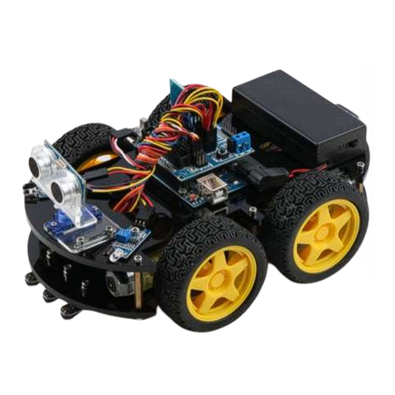
3.1.12 Bluetooth module installation Insert the bluetooth module directly into the bluetooth module interface on the expansion board, as shown in FIG. 3.1.39. Pay attention to the location of the insertion pin Figure 3.1.38 Bluetooth Moduile Picture Figure 3.1.39 Schematic diagram of bluetooth module installation 3.1.13 Expansion board wiring diagram Through the previous steps, we have completed the installation of the main structure of the car. - Page 39 specific experiment of a certain module, we will introduce it in detail through the following chapters. Figure 3.1.40 Expansion Board Connection Diagram Figure 3.1.41 Extension board wiring diagram The full installation of the car is as shown below...
- Page 40 3.1.42 Assembly Connection Diagram So far, the basic assembly of car has been completed.We believe you have some basic knowledge of your car’s structure, function and some modules through a short period of time, then you can achieve the corresponding functions only by downloading the program to the development board, each function has a corresponding program in CD , so please enjoy playing.
-
Page 41: Hummer Bot Module Experiment
3.2 Hummer Bot Module experiment 3.2.1 Walking Principle of the Car In the "Hummer-Bot" car, we choose the L298N as the motor driver chip for it is a high voltage and current full-bridge driver chip, the chip uses 15 pins package. It is a special motor driven integrated circuit (two H bridges) with high voltage and current full-bridge driver. - Page 42 ◆ The speed is adjustable ◆ The strong anti-interference ability with photoelectric isolation ◆ Overvoltage and overcurrent protection ◆ Controlling of two motors separately ◆ Controlling the stepper motor ◆ The speed control with PWM pulse width ◆ Positive and negative rotation Motor status Forward Reversal...
- Page 43 Figure .3.2.4 Schematic Diagram of Motor Drive Four DC motors with high power L298N drive enable "Hummer-Bot" to run faster than conventional two-wheel car, the acceleration time is shorter and the structure is more stable. However, in the actual application, we need to adjust the speed of the car because of environmental or other factors, yet this does not affect the forward, backward, stop, flexible steering of the car, so we use PWM to control the speed of the motor(Note: PWM is a way to simulate the simulation output via square waves with different duty cycles.), Arduino PWM port outputs a series of square waves with fixed frequency, the power and current of the motor...
- Page 44 analog signal. The PWM signal is still digital, because at any given time, the full amplitude of DC power supply is either 5V (ON) or 0V (OFF). The voltage or current source is added to the analog load with a ON or OFF repetitive pulse sequence.
- Page 45 Figure.3.2.8 L298N and Arduino Expansion Board Connection Diagram After the connection, we do not know whether the motor can work normally or not, so we need to do a simple test by copying the following code (You can also open the program in the CD directly.) into the IDE development environment and downloading to the development board.
- Page 46 Figure 3.2.9 Motor Test Flow Chart Note: This test and IO selection are only for reference, you can choose other IO ports or use other wiring methods according to your own ideas.
- Page 47 #define HB_INPUT1_PIN 6 #define HB_INPUT2_PIN 10 #define HB_INPUT3_PIN 5 #define HB_INPUT4_PIN 9 void setup() { Serial.begin(9600); pinMode(HB_INPUT1_PIN, OUTPUT); digitalWrite(HB_INPUT1_PIN, LOW); // When not sending PWM, we want it low pinMode(HB_INPUT2_PIN, OUTPUT); digitalWrite(HB_INPUT2_PIN, LOW); // When not sending PWM, we want it low pinMode(HB_INPUT3_PIN, OUTPUT);...
- Page 48 void loop() { analogWrite(HB_INPUT1_PIN, 150); analogWrite(HB_INPUT2_PIN, LOW); analogWrite(HB_INPUT3_PIN, LOW); analogWrite(HB_INPUT4_PIN, 150); delay(5000); //******** ******************************//forward analogWrite(HB_INPUT1_PIN, LOW); analogWrite(HB_INPUT2_PIN, LOW); analogWrite(HB_INPUT3_PIN, LOW); analogWrite(HB_INPUT4_PIN, LOW); delay(1000);//********************************************//stop analogWrite(HB_INPUT1_PIN, LOW); analogWrite(HB_INPUT2_PIN, 150); analogWrite(HB_INPUT3_PIN, 150); analogWrite(HB_INPUT4_PIN, LOW); delay(5000);//*********************************************//back analogWrite(HB_INPUT1_PIN, LOW); analogWrite(HB_INPUT2_PIN, LOW); analogWrite(HB_INPUT3_PIN, LOW); analogWrite(HB_INPUT4_PIN, LOW); delay(1000);...
-
Page 49: Infrared Obstacle Avoidance
3.2.2 Infrared Obstacle Avoidance 3.2.2.1 Introduction of Infrared Obstacle Avoidance Sensor Infrared obstacle avoidance module is a pair of infrared transmitting and receiving tubes, the former launches a certain frequency infrared, the receiving tube will receive the reflected infrared when the infrared detects the obstacles. - Page 50 Passive infrared detector has no light source, and it can measure the position, temperature, or infrared imaging of the detected object by receiving the characteristic spectral radiation of the detected object. Figure .3.2.10 Infrared obstacle avoidance schematic diagram Figure .3.2.11 Connection of Arduino and Sensor Note: This module can adjust the detection distance by the potentiometer, the detection distance is 2- 30cm, if it is found that the distance detection is not very sensitive, you can use the potentiometer to achieve the desired results (rotating the potentiometer clockwise will increase the detection distance;...
- Page 51 Adjustable Potentiometer Figure .3.2.12 Diagram of Distance Detection Adjustment 3.2.2.4 Wire connection As the figure shown below, the upper column is the "GND" interface, the middle column is the "VCC" interface, and the lower column is the "OUT" interface, where "A3" corresponds to the "OUT" of the left infrared obstacle avoidance, and "A4"...
- Page 52 3.2.2.5 Experimental Procedures 1, Fixing the two sensors on the car and connecting them to Arduino with wires.(Already done) 2, Testing the sensitivity of module, namely opening the switch on the battery box and the indicator will light, placing obstacles the 10cm away from the infrared tubes, adjusting the potentiometer until the output indicator lights up.
- Page 53 const int leftPin = A3; const int rightPin = A4; void setup() { Serial.begin(9600); pinMode(leftPin, INPUT); pinMode(rightPin, INPUT); delay(1000); void loop() { digitalRead (leftPin); digitalRead (rightPin); Serial.print("left:"); Serial.print(dl); Serial.print(" "); Serial.print("right:"); Serial.println(dr); Figure .3.2.14 Diagram of Data with Obstacles...
- Page 54 Figure .3.2.15 Diagram of Data without Obstacles 3.2.2.6Software Design In the above steps, we have tested the car’s driving and obstacle avoidance module respectively, they have achieved the desired results, here the "infrared obstacle avoidance" actually has been explained in this section, but we have not put the programs of two parts together, so we now integrate the program of the two parts and complete this great "infrared obstacle avoidance"...
- Page 55 void loop() = digitalRead(leftPin); = digitalRead(rightPin); && == 0) analogWrite(INPUT1_PIN,0); analogWrite(INPUT2_PIN, 200); //the speed value of motorA is 180 analogWrite(INPUT3_PIN,0); analogWrite(INPUT4_PIN, 200); //the speed value of motorB is 180 Serial.print(dl); Serial.print(" "); Serial.print(dr); Serial.print(" "); Serial.println("Turning left"); delay(300); analogWrite(INPUT1_PIN,0); analogWrite(INPUT2_PIN, 0); analogWrite(INPUT3_PIN,0);...
-
Page 56: Infrared Tracing
analogWrite(INPUT1_PIN,180);//the speed value of motorA is val analogWrite(INPUT2_PIN, 0); analogWrite(INPUT3_PIN,180);//the speed value of motorA is val analogWrite(INPUT4_PIN, 0); Serial.print(dl); Serial.print(" "); Serial.print(dr); Serial.print(" "); Serial.println("Turning right"); delay(300); analogWrite(INPUT1_PIN,0); analogWrite(INPUT2_PIN, 0); analogWrite(INPUT3_PIN,0); analogWrite(INPUT4_PIN, 0); delay(1000); //********************************************//Turning right if (dl == 1 && dr == 1) analogWrite(INPUT1_PIN,180);//the speed value of motorA is val analogWrite(INPUT2_PIN, 0);... - Page 57 line (pasting black line on the floor); you just need to make a distinct difference between the track and the ground environment. Black line tracking refers to the car drives along the black line on the white floor, it can know where to drive according to the received reflected light due to the different light reflection coefficient on the black and white floor.
- Page 58 tube on the car, the photosensitive triode will be saturated, the output end of the module is high level and the indicating diode will light. As is shown in the schematic diagram 3.2.17 (U1 is comparator, such as LM358, LM324, LM393, LM339 and a series of comparators, we use the 74HC14D comparator in TCRT5000), A and C are connected to the light emitting diode, C and E to the receiving diode, as shown in Fig.3.2.16.
- Page 59 ◆ The working voltage: 3.3V-5V ◆ Using wide voltage comparator 74HC14D, digital output (0 and 1) ◆ Easy-to-install fixed bolt holes Detailed parameters please refer to “hummer-bot\Document\ TCRT5000.pdf” Note: Correct wiring! The mainboard and electronic device may burn up if you have reverse connection between positive and negative poles.
- Page 60 3.2.3.5 Experimental Procedures 1, Fixing the sensor on the car (the assembly is completed) and connecting it to the Arduino as shown in Fig.3.2.19. 2, Making the track.If your floor is white, then you could stick a black tape to form a loop, otherwise stick a white tape, the shape of track is based on your own desires, the best width of the tape is 13-18mm.
- Page 61 void setup() { Serial.begin(9600); pinMode(A0, INPUT); pinMode(A1, INPUT); pinMode(A2, INPUT); void loop() { left, centre, right; left = digitalRead(A0); centre = digitalRead(A1); right = digitalRead(A2); Serial.print("right:"); Serial.print(right); Serial.print(" "); Serial.print("centre:"); Serial.print(centre); Serial.print(" "); Serial.print("left:"); Serial.print(left); Serial.println(" "); Figure .3.2.20 Example of the Black Track...
- Page 62 Fig. 3.2.21 The Data When the Sensor Does Not Detect the Black Line Figure 3.2.22 The Data When the Sensor Detects the Black Line From Fig.3.2.21 and Fig.3.2.22 we can see that the output is high level when the sensor does not detect the black line, low level when detects the black line.
- Page 63 the printed value is analog that, the high level is reaching 1024, the low level is 0. After we master the working principle of the sensor, our tracing car in this section comes to an end, then let us open a car journey.
- Page 64 /*Set a PWM value, the maximum value of PWM is 255, but the speed should not be too fast when tracing the car, otherwise the car will shake more in the tracing process.*/ analogWrite(INPUT1_PIN, val); analogWrite(INPUT2_PIN, //the speed value of motorA is val analogWrite(INPUT3_PIN, 0);...
-
Page 65: Ultrasonic Obstacle Avoidance
3.2.4 Ultrasonic Obstacle Avoidance In this product, we will integrate the ultrasonic module and steering engine together and make the two parts working at the same time, which greatly increases the effectiveness of the data and the flexibility of the car, the main working flow: When the power is on, steering engine will automatically rotates to 90 degrees, the MCU will read data from the reflected ultrasonic. - Page 66 Figure .3.2.25 Physical Map of Steering Gear 2. The ultrasonic An ultrasonic sensor is a device that transforms other forms of energies into ultrasonic energy with desired frequency or transforms the ultrasonic energy into other forms of energy with the same frequency. The ultrasonic sensors are commonly classified into two categories, the acoustic type and the hydrodynamic type.
- Page 67 Figure 3.2.26 Physical Map of Ultrasonic Module 3.2.4.2 Suite Parameters 1. Steering gear The steering gear has three input wires as shown in Fig.3.2.25, the red is power wire, while the brown is the ground, which guarantee the basic energy supply for the steering gear. The power supply has two kinds of specifications (one is 4.8V, the other is 6.0V)which are corresponding to different torque standards, the 6.0V torque is higher than the 4.8V torque;...
- Page 68 8, Supporting the following 2 detection methods: 1, continuous detection; 2, controlled intermittent detection; 9, Distance data format: using mm as the smallest data unit, double byte 16 hexadecimal transmission; 10, Temperature data format: using Celsius degree as the smallest unit, single byte hexadecimal transmission;...
- Page 69 Figure .3.2.27 Relationship between the Motor Output Angle and Input Pulse 2. The ultrasonic The most commonly used method of ultrasonic distance measurement is echo detection method, the ultrasonic transmitter launches ultrasonic toward a direction and starting the time counter at the same time, the ultrasonic will reflect back immediately when encountering a blocking obstacle and stopping the counter immediately as soon as the reflected ultrasonic is received by the receiver.
- Page 70 receiving time interval of the ultrasonic, which can be recorded with the time counter, and don't forget to divided it with 2. The ultrasonic is a sound wave which will be influenced by temperature. If the temperature changes little, it can be approximately considered that the ultrasonic velocity is almost unchanged in the transmission process.
- Page 71 Figure .3.2.30 Schematic Diagram of Ultrasonic Transmitting and Receiving 3.2.4.4 Experimental Procedures 1, Installing the steering gear, ultrasonic module to the car which has been completed in fourth step to the seventh step in 3.1.2) as shown in Fig.3.2.31. 2. Connecting the steering gear and ultrasonic module to the Arduino motherboard as shown in Fig.3.2.32. (you can choose other IO ports according to your own ideas).
- Page 72 Figure .3.2.31 Installation Diagram of the Steering Gear and Ultrasonic Module Figure .3.2.32 Wiring of the Steering Gear and Ultrasonic Module...
- Page 73 3.2.4.5 Wire connection As shown in the below figure, the servo's "S" is connected to pin 13, the ultrasonic "Trlg" is connected to pin 2, the "Echo" is connected to pin 3, the "VCC" pin is connected to VCC, and the "GND" pin is connected to GND.
- Page 74 mUltrasonic.SetServoDegree(90); delay(1000); void loop() { left = digitalRead(leftPin); right = digitalRead(rightPin); = mUltrasonic.GetUltrasonicFrontDistance(); ((da >= 50) && <= 2000) && (left != 0) && (right != 0)) { = 150; analogWrite(INPUT1_PIN, val);//the speed value of motorA is 255 analogWrite(INPUT2_PIN, 0); analogWrite(INPUT3_PIN, 0);...
- Page 75 analogWrite(INPUT1_PIN, 0); analogWrite(INPUT2_PIN, 0); //the speed value of motorA is 255 analogWrite(INPUT3_PIN, 0); analogWrite(INPUT4_PIN, 0); //the speed value of motorB is 255 Serial.print("Distance = "); Serial.print(da); Serial.print(" "); Serial.println("Stopped");//If the distance is less than 20cm, the car stops and outputs "stopped" delay(500);...
-
Page 76: Infrared Remote Control
In front the sections, we focus on the "automatic driving", and they are obstacle avoidance experiments. We didn't seem to have relationship with the car, it is lack of fun. Now in the next few sections, we will develop the car from other aspects to make sure that we are able to control the car personally, then we will start from the "infrared remote control", followed by "2.4G handle remote control"... - Page 77 internal oscillation circuit, timing circuit, scanning signal generator, key input encoder, instruction decoder, user code converter, digital modulation circuit and buffer amplifier and so on. It can produce a key scanning pulse signal, translate the key code, then obtain remote control commands of the keys by telecommand encoder (remote control encoding pulse).
- Page 78 amplifier and the pulse amplitude limiter, the limiter controls the pulse amplitude at a certain level, regardless of the distance of infrared transmitter and receiver. AC signal enters the band-pass filter which can pass the 30KHZ to the load wave 60KHZ and enters the comparator through the demodulation circuit. The comparator outputs high or low level and restores the output signal waveform.
- Page 79 3, Copying the following program to IDE (you can also directly open the matching program in the CD), and downloading to the development board, pulled out the transparent plastic sheet marked as "1" in the Fig.3.2.33. Then opening the serial port monitor, observing and recording the values on it while pressing keys on the remote control towards the receiving head as shown in Fig.3.2.38.
- Page 80 #include "IRremote.h" IRremote ir(12); unsigned char keycode; char str[128]; void setup() { Serial.begin(9600); ir.begin(); void loop() (keycode = ir.getCode()) { String key_name = ir.getKeyMap(keycode); sprintf(str, "Get ir code: 0x%x key name: %s \n", keycode, (char *)key_name.c_str()); Serial.println(str); else Serial.println("no key"); delay(110);...
- Page 81 The key mapping table is as follows: ST_KEY_MAP irkeymap[KEY_MAX] = { {"1", 0x45}, {"2", 0x46}, {"3", 0x47}, {"4", 0x44}, {"5", 0x40}, {"6", 0x43}, {"7", 0x07}, {"8", 0x15}, {"9", 0x09}, {"0", 0x19}, {"*", 0x16}, {"#", 0x0D}, {"up", 0x18}, {"down", 0x52}, {"ok", 0x1C}, {"left", 0x08}, {"right", 0x5A} 3.2.5.4 Wire connection...
- Page 82 3.2.5.5 Software Design 3.2.5.5.1 Program flow chart 3.2.5.5.2 Program code Code Path : “hummer-bot\Lesson\ModuleDemo\ IRremote\ IRremote.ino” #include "IRremote.h" #define INPUT1_PIN 6 // PWMB #define INPUT2_PIN 10 // DIRB --- right #define INPUT4_PIN 9 // PWMA #define INPUT3_PIN 5 // DIRA --- left RECV_PIN 12;//Define the infrared receiver pin to 12 long...
- Page 83 void setup() { Serial.begin(9600); irrecv.begin(); void loop() { byte irKeyCode; (irKeyCode = irrecv.getCode()) Serial.println(irKeyCode,HEX); (irKeyCode == advence) { analogWrite(INPUT1_PIN, val);//the speed value of motorA is val analogWrite(INPUT2_PIN, 0); analogWrite(INPUT3_PIN, 0); analogWrite(INPUT4_PIN, val); //the speed value of motorA is val else if (irKeyCode == expedite1) { val += 20;...
-
Page 84: Mobile Phone Bluetooth Control
analogWrite(INPUT2_PIN, 0); analogWrite(INPUT3_PIN, val);//the speed value of motorA is val analogWrite(INPUT4_PIN, 0); else if (irKeyCode == back) { analogWrite(INPUT1_PIN, 0); analogWrite(INPUT2_PIN, val); //the speed value of motorA is val analogWrite(INPUT3_PIN, val); //the speed value of motorA is val analogWrite(INPUT4_PIN, 0); } else { analogWrite(INPUT1_PIN, 0);... - Page 85 standard, operating frequency range is 2.4GHZ range, modulation mode is GFSK, maximum transmission power is 0db, maximum transmission distance is 80 meters, adopts original imported chip design, and supports users to modify device by AT command. Names, service UUIDs, transmit power, pairing passwords, and other instructions are convenient and quick to use.
- Page 86 App: 3) If Bluetooth information is not displayed, please pull down to refresh,if it still don’t work,please close and reopen it. 4) Select the JDY-16 Bluetooth model. 5) There will pop up a window which indicate connection success and jump to the operation interface:...
- Page 87 6) Click the second option “SK Service”,then click the first option “SK KEYPRESSED”: 7) In the end you will jump to the user interface,click “WRITING” to send. 8) Write data on the pink line, click “send” to send.
- Page 88 Serial port display as follow: 9) You can also send date through Arduino serial port to app.
- Page 89 10) The result as below: Picture. 3.2.28 During above test, both the PC and Android can send and receive data normally, indicating that the Bluetooth module communicates normally and achieves the expect effect. Next, it can be used as a bridge between "Aurora"...
- Page 90 Since the wireless communication is involved, one of the essential issues is the communication problem between the two terminals. But there is no common "language" between them, so designing communication protocols are required to ensure a perfect interaction between Android and Arduino. The main process is: the Android identification terminal packs the detected commands into the corresponding data packets, and then sends them to the Bluetooth module (JDY-16).
- Page 91 typedef enum E_BATTERY = 1, E_LED = 2, E_BUZZER = 3, E_INFO = 4, E_ROBOT_CONTROL = 5, E_ROBOT_CONTROL_SPEED = 6, E_TEMPERATURE = 7, E_IR_TRACKING = 8, E_ULTRASONIC = 9, E_VERSION = 10, E_UPGRADE = 11, }E_CONTOROL_FUNC The data means the specific control value of a car, such as speed, angle. “Checksum”...
- Page 92 Fig.3.2.50 the Interface of Android APP In the above Figure.3.2.50: The "A, B" sections are the acceleration and deceleration buttons. The "C" section includes the dashboard and the digital display area, and the two parts displaying synchronously. They represent the current speed. The "D"...
- Page 93 cathode of the DC power, the RXD port is connected to the TXD port on Arduino extended board, TXD port is connected to RXD port on the board, as shown in Fig.3.2.52. Note: Since Arduino UNO has only one serial port, the Bluetooth must be disconnected from the serial port when downloading the program, otherwise the download will fail.
- Page 94 Figure .3.2.52 Installation of Bluetooth Module 2, Open the mobile phone Bluetooth and the APP (There is a software installation package on the CD, latter we will launch the IOS version.) You will see that the flashing of the Bluetooth module indicator slows down after successful connection.
- Page 95 Figure .3.2.53. Diagram of APP Control In Fig.3.2.53, we can see the logo "1" and "2". When the Bluetooth connection is successful, sliding green dot marked as "1" in any direction, the car will move towards the corresponding direction. Switching on the gravity sensor marked in "2", the APP is switched to the gravity induction mode, and you can control the movement direction of the car by shaking the mobile phone.
- Page 96 3.2.6.6 Software Design 3.2.6.6.1 Program flow chart 3.2.6.6.2 Program Code Code Path “hummer-bot\Lesson\Advanced Experiment\Buletooth\ Buletooth.ino”...
- Page 97 #include "Hummerbot.h" #include "ProtocolParser.h" #include "KeyMap.h" #include "debug.h" #define INPUT2_PIN 10 // PWMB #define INPUT1_PIN 6 // DIRB --- right #define INPUT4_PIN 5 // PWMA #define INPUT3_PIN 9 // DIRA --- left ProtocolParser *mProtocol ProtocolParser(); Hummerbot hbot(mProtocol, INPUT2_PIN, INPUT1_PIN, INPUT3_PIN, INPUT4_PIN); void setup() Serial.begin(9600);...
- Page 98 void loop() mProtocol->RecevData(); switch(hbot.GetControlMode()) case E_BLUETOOTH_CONTROL: HandleBluetoothRemote(); DEBUG_LOG(DEBUG_LEVEL_INFO, "E_BLUETOOTH_CONTROL \n"); break; default: break;...
-
Page 99: Ps2 Handle (Optional)
3.2.7 PS2 Handle (Optional) 3.2.7.1 Suite Introduction PS2 handle is SONY game remote control handle, SONY series game host is very popular in the world. Someone has come up with the idea of the PS2 handle, cracked the communication protocol, so that the handle can be connected to other devices for remote control, such as remote control of our familiar four wheeled vehicles and robots. - Page 100 "ANALOG" in different handles, but it will not affect the usefulness), you can choose "red light mode" or "green light mode". Some users see that the handle and receiver cannot match properly! Most of the problems are the incorrect wiring of the receiver and the program problems. Solution: The receiver should only be connected with power supply (power line must be connected correctly), not any data lines and clock lines.
- Page 101 3.2.7.2 Experimental Procedure 1、In order to wire simply, we use the PS2 receiver head adapter board and Arduino connection as follows: As shown in the below figure, the six lines of the receiving head are connected to the following places respectively.
- Page 102 Fix the receiver head to the cart with a cable tie (red frame area in Figure 3.2.55), as shown in Figure 2.3.56. Figure 3.2.55 Receive Head Fixed Bit Figure 3.2.56 Receiving head fixing diagram...
- Page 103 3、Lead the wire according to the hole marked “1” in Figure 3.2.57, and connect the wire to the Aruino expansion board with reference to Figure 2.3.58. After the completion, as shown as Figure 2.3.57. Figure 3.2.57 Wire Connection Diagram Figure 3.2.58 Connection of Arduino and Receiving Head Wires “Lesson\ModuleDemo\PS2X\PS2X.ino”...
- Page 104 on the remote control, you can see the corresponding data on the "serial monitor", as shown in Figure 3.2.59. Figure 3.2.59 "serial monitor" data display...
- Page 105 3.2.7.3 Software Design #include "PS2X_lib.h" //for v1.6 /****************************************************************** * set pins connected to PS2 controller: - 1e column: original - 2e colmun: Stef? * replace pin numbers by the ones you use ******************************************************************/ #define PS2_DAT #define PS2_CMD #define PS2_SEL #define PS2_CLK /****************************************************************** * select modes of PS2 controller: - pressures = analog reading of push-butttons...
- Page 106 void setup() { Serial.begin(9600); delay(500); //added delay to give wireless ps2 module some time to startup, before configuring it //CHANGES for v1.6 HERE!!! **************PAY ATTENTION************* //setup pins and settings: GamePad(clock, command, attention, data, Pressures?, Rumble?) check for error error = ps2x.config_gamepad(PS2_CLK, PS2_CMD, PS2_SEL, PS2_DAT, pressures, rumble);...
- Page 107 switch(type) { case Serial.println("Unknown Controller type found "); break; case Serial.println("DualShock Controller found "); break; case Serial.println("GuitarHero Controller found "); break; case Serial.println("Wireless Sony DualShock Controller found "); break; void loop() { /* You must Read Gamepad to get new values and set vibration values ps2x.read_gamepad(small motor on/off, larger motor strenght from 0-255) if you don't enable the rumble, use ps2x.read_gamepad();...
- Page 108 if(ps2x.Button(UP_STRUM)) //will be TRUE as long as button is pressed Serial.println("Up Strum"); if(ps2x.Button(DOWN_STRUM)) Serial.println("DOWN Strum"); if(ps2x.Button(PSB_START)) //will be TRUE as long as button is pressed Serial.println("Start is being held"); if(ps2x.Button(PSB_SELECT)) Serial.println("Select is being held"); if(ps2x.Button(ORANGE_FRET)) { // print stick value IF TRUE Serial.print("Wammy Bar Position:");...
- Page 109 vibrate = ps2x.Analog(PSAB_CROSS); //this will set the large motor vibrate speed based on how hard you press the blue (X) button (ps2x.NewButtonState()) { //will be TRUE if any button changes state (on to off, or off to on) if(ps2x.Button(PSB_L3)) Serial.println("L3 pressed");...
- Page 110 In the above program, we instructed to read the test button. In this experiment we want to implement the PS2 remote control car function. We firstly define all the button functions as follows: Figure .3.2.60 Functions of PS2 Handle Buttons Mark UP: move forward Mark DOWN: move backward Mark LEFT: turn left...
- Page 111 The program flow chart is as follows:...
Need help?
Do you have a question about the Hummer-Bot-2.0 and is the answer not in the manual?
Questions and answers