
Related Manuals for Keywish Hummer-Bot


Summary of Contents for Keywish Hummer-Bot
- Page 1 Hummer-Bot Instruction Manual Github https://github.com/keywish/keywish-hummer-bot...
- Page 2 Versio Data Description Author 2017/9/16 V-1.0 Create Baron.li 2017/9/23 V-1.1 modify Ken.chen V-1.2 Review Ken.chen 2017/10/18 V-1.3 Review Zach.zhou 2017/11/15 V-1.4 Review Baron.li 2017/12/8 V-1.5 Modify ir/blutooth module Ken.chen 2018/3/11 V-1.6 2018/4/20 Add device instructions Baron.li V-1.7 2018/5/3 Add installation details picture Baron.li...
-
Page 3: Table Of Contents
table of Contents Chapter1 Introduction ................. 1 1.1 Writing Purpose ..............1 1.2 Product Introduction ............... 2 Chapter2 Preparations ................. 8 2.1 About Arduino ................ 8 2.2 Why Choosing Arduino ............8 Chapter3 Experiments ............... 11 3.1 Assembly of the Car ............. 11 3.1.1 Bottom Mounting of the Car ........ -
Page 4: Chapter1 Introduction
In addition, "Hummer-Bot" has a variety of modes, can be switched freely and completed a variety of development on one platform, which is the best choice for every electronic enthusiasts. -
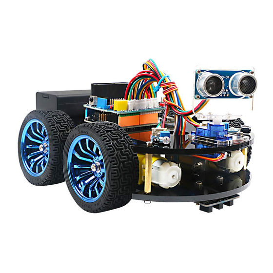
Page 5: Product Introduction
This manual is a specifications for "Hummer-Bot" , the file whose format is PDF which is in the CD along with our product requires the corresponding software to open. It contains detailed schematic diagrams and complete source codes for all instances, the codes won't have any mistake under our strict test. In... - Page 6 Product component invento Note: Please refer to the following table for instructions for use of each accessory device:...
-
Page 11: Chapter2 Preparations
Chapter2 Preparations 2.1 About Arduino At the beginning of the study, let us read this little story: In the north of Italy, there is a picturesque town which across the blue green Dora Baltea River whose name is Ivrea, it is a place full of colorful history for it is where the king was born. - Page 12 kit. Arduino also simplifies the working process of the microcontroller, but compared with other systems, Arduino is more advantageous in many places, especially for teachers, students and some amateurs: 1, Cheap - compared with other platforms, the Arduino board is pretty cheap. The cheapest version of Arduino can be made by hand, even if it's finished, the price will not exceed 200 yuan.
- Page 13 Fig 2.2 Several commonly usedArduino...
-
Page 14: Chapter3 Experiments
Chapter3 Experiments 3.1 Assembly of the Car 3.1.1 Bottom Mounting of the Car First we open the box, take out the car body (two black acrylic), screwdriver, M4x12 screws, six angle coupling and matching set screws, four black&red welding wires and four motor and wheels. The first step is to Mounting motor mount. - Page 15 After the completion as shown.
- Page 16 The second step is to Welding wire on the motor.
- Page 17 After the completion as shown.
- Page 18 The third step is to fix the wire on the motor with tie tape. The fourth step is to Mount aluminum alloy brackets on acrylic plates. first removing the protective film on the acrylic, and then fixing it according to the corresponding space. After the installation, the front face is shown in Fig.3.1.4, and the back is shown in Fig.3.1.5.
- Page 19 Fig.3.1.3 Diagram of Aluminum Alloy Bracket Installation...
- Page 20 Fig.3.1.4 Diagram of Motor Installation Fig.3.1.5 Fixing Screw for Motor...
- Page 21 The fifth step is to install the connecting shaft for the purpose of fastening the connecting motor and the wheel, and use the connecting shaft as the power transmission link. Fig.3.1.6 shows the connecting shaft and the set screws, first screwing the screws into the connecting shaft (not too tight, otherwise the motor transmission shaft cannot be inserted into the connecting shaft), Then insert the smooth side of the motor's drive shaft into the machine screw, as shown in Figure 3.1.7.
- Page 22 Fig.3.1.7 Diagram of Connecting Shaft Installation Fig.3.1.8 After Installation (set screws must be stuck in the smooth side)
- Page 23 Fig.3.1.9 Diagram after Complete Installation The sixth step is to install wheels, "Hummer-Bot" uses racing wheels which grip stronger, less friction, more stable than the traditional wheels. The wheel mounting method is relatively simple. Then inserting the connecting shafts into the wheels as shown in Fig.3.1.10 and screwing tightly as shown in Fig.3.1.11.
- Page 24 Fig.3.1.10 Diagram of Wheel Installation Fig.3.1.10 Diagram of Wheel Screw Fixation...
- Page 25 In the fourth step we said that don't screw too tight, because it is not convenient to adjust the wheels later. As shown in Fig.3.1.11,the installed wheels would have some tilt, then we need to adjust the motor by hand gently until the wheels and the acrylic become parallel, then tighten the screws. Fig.3.1.11 Adjusting Wheels and Tightening Screws The seventh step is to install the motor drive.
- Page 26 First fix the screw on the motor driver board, as shown below Then install the motor driver board on the acrylic board, as shown below Fig.3.1.12 Diagram of Motor Drive Installation...
- Page 27 The eighth step is to connect the motor wires to the drive, note that the rotation direction of the two motors require to be identical, so we should modify and debug the program first when wiring. Connecting the motor to any motor driver board, as shown in Fig.3.1.13, then connecting the two wires on battery box to the motor drive +12v (red) and GND (black), and leading a wire from +5V to "3"...
- Page 28 Fig.3.1.14 Diagram of Connection Between Motors and Drive Board The ninth step is to install the tracing module and fix the module to the acrylic board according to the Fig.3.1.15. First, screwing the screws to the tracing module(Use two nuts here), as shown in Fig.3.1.16, and then connecting the 3Pin wire to the "1"...
- Page 29 Fig.3.1.15 Diagram of Tracing Module Installation...
- Page 30 Fig.3.1.16 Diagram of Screw Brackets Fig.3.1.17 The Back of Complete Installation...
-
Page 31: Surface Mounting Of The Car
3.1.2 Surface Mounting of the Car The first step is to install the battery box and the Arduino mainboard, this step is quite simple, install the corresponding package to "3"and "2" in Fig.3.1.19, the complete installation is shown in Fig.3.1.20. Fig.3.1.19 Diagram of Top Surface Device Installation... - Page 32 First install the screws on the UNO After the completion as shown...
- Page 33 Then install UNO on acrylic plates Fig.3.1.20 Diagram of Arduino Mainboard and Battery Box Installation...
- Page 34 The second step is to install the total of 6 support screws which are mainly used to connect two piece acrylic board. In Fig.3.1.19, we can see the "1" logo where there are 6 holes, these are the screw fixing holes, The installation is shown in Fig.3.1.21and the complete installation is shown in Fig.3.1.22.
- Page 35 The third step is to install the steering gear and the bracket. In Fig.3.1.19, the "4" logo is the actuator mounting position. The device used as shown ,The complete installation is shown in Fig.3.1.23. First, install the servo fixing bracket, that is, install the bracket in the place as shown in the figure, and add the fixing screw...
- Page 36 Step 2: Install the servo, install it as shown in the figure The third step: use two screws to fix the servo. Fig.3.1.23 Diagram of Steering Gear Installation...
- Page 37 After installing the steering gear, you can add the ultrasonic module on it. In order to reduce the later steering angle adjustment, we adjust the steering gear to 90 degrees, and copy the following program to the compiler environment (you can also directly open the program in the CD), then connect the signal line(Orange) on steering gear to the 13 IO port on Arduino, After the servo rotates to 90°...
- Page 38 Fig.3.1.24 Diagram of Steering Gear Angle Adjustment The fifth step is to install ultrasonic bracket, fix the bracket on the steering gear, as shown in Fig.3.1.25. Fig.3.1.25 Diagram of Ultrasonic Bracket Installation...
- Page 39 The sixth step is to install infrared obstacle avoidance module in the two holes marked as "6" in Fig.3.1.19, as shown in Fig.3.1.26. Fig.3.1.26 Diagram of Infrared Obstacle Avoidance Installation...
- Page 40 The seventh step is to install infrared remote control receiving head on the Arduino extended board and fixed it with a screw, as shown in Fig.3.1.27. Pay attention to the installation direction. Fig.3.1.27 Diagram of Infrared Remote Control Receiving Head Installation The eighth step is to install the voltage display module in the back of battery box to logo "A"marked in Fig.3.1.28, and insert the wire into the hole identified as "B"...
- Page 41 Fig.3.1.29 Diagram of Voltage Display Module Installation Connect the power cable: First find the matching two power cables (the same as the wires used by the motor, one red and one black) and connect the two cables to the DC power head. The DC power connector is shown in Figure 3.1.29.
- Page 42 Fig.3.1.32. Wire welding schematic The tenth step is the whole assembly, first inserting the 4Pin wire into IN1-IN4 on the motor drive, and threading the other end wire of the tracing module from the bottom to the top of the car. Then connecting two wires of the battery box and the voltage display module 、DC power head to the +12V (red) and GND (black) on the motor drive board.
- Page 43 Fig.3.1.33 Diagram of Wires Arrangement Fig3.1.34 the Effect of Whole Assembly...
- Page 44 Fig3.1.35the Effect of Whole Assembly So far, the basic assembly of car has been completed,we believe you have some basic knowledge of your car’s structure, function and some modules through a short period of time, then you can achieve the corresponding functions only by downloading the program to the development board, each function has a corresponding program in CD , so please enjoy playing.
-
Page 45: Development Of The Car
Expansion board wiring diagram After the car is assembled, the wire connection can be referenced as shown in the figure. Of course, it will be described in detail later in the program. 3.2 Development of the Car 3.2.1 Walking Principle of the Car "Motor"... - Page 46 Motor drive - it is a necessary condition for the motor to play its superior performance. Its main function is to provide sufficient current and power for the motor. In the "Hummer-Bot" car, we choose the L298N as the motor driver chip for it is a high voltage and current full-bridge driver chip, the chip uses 15 pins package.
- Page 47 ◆ The speed is adjustable ◆ The strong anti-interference ability with photoelectric isolation ◆ Overvoltage and overcurrent protection ◆ Controlling of two motors separately ◆ Controlling the stepper motor ◆ The speed control with PWM pulse width ◆ Positive and negative rotation Motor status Forward Reversal...
- Page 48 Fig.3.2.4 Schematic Diagram of Motor Drive Four DC motors with high power L298N drive enable "Hummer-Bot" to run faster than conventional two-wheel car, the acceleration time is shorter and the structure is more stable. However, in the actual application, we need to adjust the speed of the car because of environmental or other factors, yet this does not affect the forward, backward, stop, flexible steering of the car, so we use PWM to control the speed of the motor(Note: PWM is a way to simulate the simulation output via square waves with different duty cycles.),...
- Page 49 Fig.2.4.6 Relation between Pulse and Voltage In the "Hummer-Bot" car experiment, we use Arduino UNO R3 as the main control board. By referring to the chip data, we will know that Arduino UNO has 6 PWM pins, namely digital interfaces 3, 5, 6, 9, 10,...
- Page 50 Fig.2.4.7 Connection between Arduino and L298N Drive Board After the connection, we do not know whether the motor can work normally or not, so we need to do a simple test by copying the following code(you can also open the program in the CD directly) into the IDE development environment and downloading to the development board.
- Page 51 analogWrite(M1,0); analogWrite(E1, 150); //the speed value of motorA is 150 analogWrite(M2,0); analogWrite(E2, 150); //the speed value of motorB is 150 delay(5000); //******** ******************************//forward analogWrite(M1,0); analogWrite(E1, 0); //the speed value of motorA is 0 analogWrite(M2,0); analogWrite(E2, 0); //the speed value of motorB is 0 delay(1000);...
-
Page 52: Infrared Obstacle Avoidance
By now, the car can move normally, are you happy and excited? But this is just the beginning, the car can just fool-turning without significance, there will be more fun if we add it some "organs".Now we will equip the car with several commonly-used sensors, so it will have a new understanding of the world. 3.2.2 Infrared Obstacle Avoidance 3.2.2.1 Introduction of Infrared Obstacle Avoidance Sensor Infrared obstacle avoidance module is a pair of infrared transmitting and receiving tubes, the former... - Page 53 and avoids the obstacle beautifully. The schematic diagram of the sensor is shown in Fig.3.2.8. Infrared detector can be divided into active and passive according to its working mode. Active infrared detector is equipped with infrared light source, it can detect the location of the object through covering the light source, reflection, refraction and other optical means.
- Page 54 Fig.3.2.9 Connection of Arduino and Sensor Note: This module can adjust the detection distance by the potentiometer, the detection distance is 2- 30cm, if it is found that the distance detection is not very sensitive, you can use the potentiometer to achieve the desired results ( rotating the potentiometer clockwise will increase the detection distance;...
- Page 55 3, Module test.copying the following code to the IDE compiler environment (you can also open the program directly in the CD), downloading it to the development board, opening the serial port monitor (baud rate is 9600) and observing the changes of data when there is a obstacle (Figure 3.2.11) and no obstacle (Figure 3.2.12).
- Page 56 Fig.3.2.11 Diagram of Data with Obstacles Fig.3.2.12 Diagram of Data without Obstacles...
- Page 57 3.2.2.5 Software Design In the above steps, we have tested the car’s driving and obstacle avoidance module respectively, they have achieved the desired results, here the "infrared obstacle avoidance" actually has been explained in this section, but we have not put the programs of two parts together, so we now integrates the program of the two parts and complete this great "infrared obstacle avoidance"...
- Page 58 receive the value of the sensor, we only return "0" and "1" ", But the same way to judge. The reason why I did not use digital IO, because we use the digital IO port in other places.*/ analogWrite (M1,0); analogWrite(E1, 180);...
- Page 59 analogWrite(M1,255); //the speed value of motorA is 255 analogWrite(E1, 0); analogWrite(M2, 0); analogWrite(E2, 255); //the speed value of motorB is 255 Serial.print(dl); Serial.print(" "); Serial.print(dr); Serial.print(" "); Serial.println("Turning around");/* Through the "Serial Monitor" print the current status of the car and the value collected by the sensor.*/ delay(500);...
-
Page 60: Infrared Tracing
analogWrite(E2, 0); /* Car must stop after each rotation, if you do not stop there will be the phenomenon of rotating around. * / delay(1000); //*********************************//Turning right >= && >= 38) / * Judge two values collected by the sensor. If the value collected by the left sensor is greater than or equal to 38 and the right value is greater than or equal to 38, execute the following program in {} (dl>... - Page 61 In the "Hummer-Bot" car, we use the TCRT5000 sensor as tracing module, TCRT5000 infrared reflection sensor is a photoelectric sensor which consists of an infrared emitting diode and a NPN infrared photoelectric transistor.
- Page 62 74HC14D comparator in TCRT5000), A and C are connected to the light emitting diode, C and E to the receiving diode, as shown in Fig.3.2.13. In the "Hummer-Bot" car, we use three modules, two in the left and right sides, one in the middle. Its installation is shown in Fig.3.2.16,the tracing sensors are in a straight line.
- Page 63 Note: Correct wiring! Do connect the positive and negative pins correctly, or the mainboard and electronic device may burn up. Connecting the VCC to 3.3V or 5V, the OUT output port to the microcontroller IO port directly. The I/O port on Arduino should be set for input mode / receiving mode, otherwise it can not be used. As for other MCU, such as ARM or more advanced control boards, if the I/O ports need to be used as the input and output mode, they have to be set to the input mode / receiving mode.
- Page 64 Serial.print("left:"); Serial.print(left); Serial.println(" "); Fig.3.2.18 Example of the Black Track Fig. 3.2.19 The Data When the Sensor Does Not Detect the Black Line...
- Page 65 Figure 3.2.20 The Data When the Sensor Detects the Black Line From Fig.3.2.19 and Fig.3.2.20 we can see that the output is high level when the sensor does not detect the black line, low level when detects the black line. We use the analog port to collect the sensor’s signal, so the printed value is analog that, the high level is reaching 1024, the low level is 0.
- Page 66 Fig.3.2.21 the Tracing Flow Chart 3. Program Explanation = 5; //PWMA = 9; //DIRA****************************************left = 6; //PWMB = 10; //DIRB****************************************right /* Define 4 motor control terminals, connected to IN1-IN4 on the motor drive board.*/ void setup() Serial.begin(9600); /* Set the baud rate to 9600 * void loop() left1,centre,right1;...
- Page 67 if((right1 >= 975)&&(centre <= 8)&&(left1 >= 975)) / * Judge the collected value, if right1> = 975 and left1> = 975 are greater than 975, the left and right sensors do not detect the black line, the center <= 8 shows that the middle sensor detects the black line, so the car will Drive along the black line.
-
Page 68: Ultrasonic Obstacle Avoidance
analogWrite (M1,0); analogWrite(E1, val); //the speed value of motorA is val analogWrite (E2,0); analogWrite(M2, val); //the speed value of motorB is val if((right1 <= 8)&&(centre <= 8)&&(left1 <= 8)) / * The value collected to judge, if the center <= 8, left1 <= 8 and right1 <= 8 are greater than 8, indicating 3 sensors have detected a black line, then the car has reached the "ten"... - Page 69 Fig.3.2.22 Diagram of Steering Gear Fig.3.2.23 Composition of Steering Gear...
- Page 70 Distance measurement with the ultrasonic is also a hot spot. In the "Hummer-Bot" car, we use HC-SR04 ultrasonic module which has the 2cm-400cm non-contact distance sensing function, the measurement accuracy can achieve to 3mm; the temperature sensor can correct the measured results using the GPIO communication mode, the module has a stable and reliable watchdog.
- Page 71 Fig.3.2.25 Physical Map of Ultrasonic Module 3.2.4.2 Suite Parameters 1. Steering gear The steering gear has three input wires as shown in Fig.3.2.25, the red is power wire, while the brown is the ground, which guarantee the basic energy supply for the steering gear. The power supply has two kinds of specifications (one is 4.8V, the other is 6.0V)which are corresponding to different torque standards, the 6.0V torque is higher than the 4.8V torque;...
- Page 72 8, Supporting the following 2 detection methods: 1, continuous detection; 2, controlled intermittent detection; 9, Distance data format: using mm as the smallest data unit, double byte 16 hexadecimal transmission; 10, Temperature data format: using Celsius degree as the smallest unit, single byte hexadecimal transmission;...
- Page 73 Fig.3.2.27 Relationship between the Motor Output Angle and Input Pulse 2. The ultrasonic The most commonly used method of ultrasonic distance measurement is echo detection method, the ultrasonic transmitter launches ultrasonic toward a direction and starting the time counter at the same time, the ultrasonic will reflect back immediately when encountering a blocking obstacle, and stopping the counter immediately as soon as the reflected ultrasonic is received by the receiver.
- Page 74 receiving time interval of the ultrasonic, which can be recorded with the time counter, and don't forget to divided it with 2. The ultrasonic is a sound wave which will be influenced by temperature. If the temperature changes little, it can be approximately considered that the ultrasonic velocity is almost unchanged in the transmission process.
- Page 75 interrupt request signal to the microcontroller P3.3, the Arduino will stop the time counter when detecting low level. Fig.3.2.30 Schematic Diagram of Ultrasonic Transmitting and Receiving 3.2.4.4 Experimental Procedures 1, Installing the steering gear, ultrasonic module to the car which has been completed in fourth step to the seventh step in 3.1.2) as shown in Fig.3.2.31.
- Page 76 Fig.3.2.31 Installation Diagram of the Steering Gear and Ultrasonic Module Fig.3.2.32 Wiring of the Steering Gear and Ultrasonic Module...
- Page 77 3.2.4.5 Software Design 1. Diagram of the program 2. Introduction of the program #include <Servo.h>/* In this section, we use the steering gear, so we need to call the steering gear library file. As for what is in the library file, we will not study it. Interested friends can drive for research.
- Page 78 head.write(90); / * The servos swivel to 90 (center) during initialization, because some servos may have errors, so they are not necessarily centered at 90 degrees, so be fine-tuned where the servos are centered at 90 degrees. * / delay(1000); void loop() analogWrite(TrigPin, 0);...
- Page 79 digitalWrite(M1,0); analogWrite(E1, val); //the speed value of motorA is val digitalWrite(M2,0); analogWrite(E2, val); //the speed value of motorB is val Serial.print("Distance = "); Serial.print(da); Serial.print(" "); Serial.println("Moving advance40"); delay(500); / * If the distance is more than 40cm, move forward and output "Moving advance 40", indicating that the obstacle is more than 40cm from the car else if <= 20)
- Page 80 Serial.print(dl); Serial.print(" "); / * Ultrasonic acquisition of the left side of the car and obstacles distance, and then assigned to dl, then print on the "Serial Monitor" * / head.write(0); / * Servo steering from the original 180 degrees to 0 degrees, the right side of the car * / delay(1000);...
- Page 81 // Special case If the left return distance is greater than 1000, the probe is blocked and turn right at this moment else if >= && <= 1000 && > dl) digitalWrite(M1,180); //the speed value of motorA is 180 analogWrite(E1, 0); digitalWrite(M2,0);...
-
Page 82: Infrared Remote Control
3.2.5.1 Suite Introduction Infrared remote control is widely used in every field which is known to everyone, since it can control other electrical appliances, naturally it can control the Hummer-Bot car. Let us take a look at the infrared remote control first:... - Page 83 In the Hummer-Bot car, the integrated infrared receiving head has three pins, including the power supply pin, grounding and signal output pin. The circuit is shown in Fig.3.2.34. Ceramic capacitors is a decoupling capacitor which can filter the output signal interference.
- Page 84 The comparator outputs high or low level and restores the output signal waveform. The system procedure diagram is shown in Fig.3.2.35. Code Modulation Keyboard Remote Control Transmitter Demodulation Light/electronic Amplification Decode Remote Control Receiver Fig.3.2.35 Remote Control System Diagram 3.2.5.4 Experimental Procedures 1, Installing the infrared receiving head on the development board (if it has been installed in the the eighth step in "3.1.2", please ignore.
- Page 85 3, Copying the following program to IDE (you can also directly open the matching program in the CD), and downloading to the development board, pulled out the transparent plastic sheet marked as "1" in the Fig.3.2.33. Then opening the serial port monitor, observing and recording the values on it while pressing keys on the remote control towards the receiving head as shown in Fig.3.2.37.
- Page 86 In Fig.3.2.37, we can see the two value "FFFFFFFF" and "FF18E7", "FF18E7" is the code of a key on the remote control, "FFFFFFFF" means that the code has been received, waiting to receive the next code. 3.2.5.5 Software Design #include <IRremote.h>*/ In this section, we use infrared remote control, so we need to call the corresponding library file, as for what is in the library file, we will not study, and interested friends can drive research.
- Page 87 val=150; analogWrite (M1,0); analogWrite(E1, val); //the speed value of motorA is val analogWrite (M2,0); analogWrite(E2, val); //the speed value of motorB is val irrecv.resume(); // Receive the next value if(results.value == expedite1) / * Judgment on the value received, if this value is expedite1, execute the command in {} below, here is the acceleration 1 command.
- Page 88 if(results.value == left) / * Judgment on the received value, if the value is left, execute the command in the following {}, here is the instruction to the left. * / val=150; analogWrite (M1,0); analogWrite(E1, val); //the speed value of motorA is val analogWrite (E2,0);...
-
Page 89: Ps2 Handle (Optional)
analogWrite(M1, val); //the speed value of motorA is val analogWrite (E2,0); analogWrite(M2, val); //the speed value of motorA is val irrecv.resume(); // 接收下一个值 Serial.println(results.value, HEX); // Output the receive code in hexadecimal Serial.println();// Add a blank line for easy viewing of the output irrecv.resume();... - Page 90 Fig.3.2.39 PS2 Wireless Handle The PS2 handle is composed of the handle and the receiver, the handle uses two AAA batteries as power supply. The controller and receiver use the same power supply whose voltage range is 3~5V, overvoltage, reverse connection will cause the receiver to burn out. There is a power switch on the handle, ON /OFF, when you switch it to ON, the light on handle will not stop flashing until the receiver is searched.
- Page 91 Fig.3.2.40 Remote Control Receiver Module There are 9 interfaces at the end of the receiving head, each of which is shown in the following table: DI/DAT DO/CMD CS/SEL Note: The appearance of the receiver will be different due to different batches, some with a power light, some without, but the use and definition of the pins are the same.
- Page 92 ACK: the response signal from the handle to the host. This signal changes to low in the last cycle of each 8- bit data sending, and the CS remains low. If the CS signal do not remain low, the PS host will try another device in about 60 microseconds.
- Page 93 Fig.3.2.42 Receiving Head Position Fig.2.3.43 Installation of Receiving Head...
- Page 94 3, Drawing the wire according to the hole at "1" in Fig.3.2.44, the connecting the wire to the Aruino extended board with reference to Fig.2.3.45 as shown in Fig.2.3.44. Fig.3.2.44 Physical Map of Wiring Fig.2.3.45 Diagram of Wiring between Arduino and Receiver Head...
- Page 95 4, Opening the "remote control testing program" in the CD, and copying the library folder (PS2X_lib) to the "libraries"folder in the Arduino IDE installation path, as shown in Fig.2.4.14, otherwise the compiler cannot pass. In addition, downloading the program to the Arduino development board, opening the PS2 remote control, if the receiving head and remote control has been connected (or pairing successfully), the receiver head indicator will always be on, otherwise the LED lights will flash constantly.
- Page 96 void setup() Serial.begin(9600); error = ps2x.config_gamepad(11,7,8,4, true, true); / * Set the receiving port on the Arduino * / void loop() ps2x.read_gamepad(false, vibrate); / * Read the signal received by the receiver * / if(ps2x.Button(PSB_L3)) / * If the received signal is PSB_L3, execute the command in {}, ie stop, "PSB_L3"...
- Page 97 handle is pressed. Through the "fourth step in the experimental step" we can get the code of all the buttons * / val=200; analogWrite (E1,0); analogWrite(M1, val); //the speed value of motorA is val analogWrite (M2,0); analogWrite(E2, val); //the speed value of motorA is val delay(200);...
- Page 98 if(ps2x.Button(PSB_L1)) / * If the received signal is PSB_L1, execute the command in {}. * / = ps2x.Analog(PSS_LY); / * Read the value of PSS_LY, that is, the joystick value, and assign this value to the variable vb. The joystick range is 0-255. When you press L1, you can toggle the joystick to generate the corresponding value.
- Page 99 Fig.3.2.46 Functions of PS2 Handle Buttons PS2 handle description: Mark 1: turn left Mark 2: turn right Mark 3: right joystick (Mark 5) control key. When the R1 is pressed, the right joystick will work. Mark 4: left joystick (Mark 6) control key. When L1 is pressed, the left joystick will work. Mark 5: right joystick Mark 6: left joystick Mark 7: move forward...
-
Page 100: Mobile Phone Bluetooth Control
3.2.7 Mobile Phone Bluetooth Control 3.2.7.1 Suite Introduction Bluetooth is a wireless technology standard that enables short distance data exchange between fixed devices, mobile devices and building personal domain networks (using 2.4~2.485GHz ISM band UHF radio waves). Bluetooth technology was originally created by Ericsson in 1994 as an alternative to the RS232 data cable. - Page 101 Fig.3.2.47 HC-05 Module 3.2.7.2 Bluetooth protocol Using Bluetooth to control the car means we use the Android app to control the Bluetooth sending instructions to the Arduino serial port, so as to control the motor's forwarding, reversing, speed and so on. Since the wireless communication is involved, one of the essential issues is the communication problem between the two terminals.
- Page 102 typedef enum E_BATTERY = 1, E_LED = 2, E_BUZZER = 3, E_INFO = 4, E_ROBOT_CONTROL = 5, E_ROBOT_CONTROL_SPEED = 6, E_TEMPERATURE = 7, E_IR_TRACKING = 8, E_ULTRASONIC = 9, E_VERSION = 10, E_UPGRADE = 11, }E_CONTOROL_FUNC The data means the specific control value of a car, such as speed, angle. The checksum is the xor result of each data bit.
- Page 103 Fig.3.2.48 the Interface of Android APP In the above Figure.3.2.48: The "A, B" sections are the acceleration and deceleration buttons. The "C" section includes the dashboard and the digital display area, and the two parts displaying synchronously. They represents the current speed. The "D"...
- Page 104 cathode of the DC power, the RXD port is connected to the TXD port on Arduino extended board, TXD port is connected to RXD port on the board, as shown in Fig.3.2.51. Note: Since Arduino UNO has only one serial port, the Bluetooth must be disconnected from the serial port when downloading the program, otherwise the download will fail.
- Page 105 Fig.3.2.51 Installation of Bluetooth Module 3, Opening the mobile phone Bluetooth to find the Bluetooth name and connect (default Bluetooth name is HC-05, password is 1234). When the connection is successful, opening the APP (there is a software for Android mobile phone in the CD, latter we will launch the IOS version) and selecting Bluetooth name in APP and connecting as shown in Fig.3.2.52.
- Page 106 Fig.3.2.53. Diagram of APP Control In Fig.3.2.53, we can see the logo "1" and "2". When the Bluetooth connection is successful, sliding green dot marked as "1" in any direction, the car will move towards the corresponding direction. Switching on the gravity sensor marked in "2", the APP is switched to the gravity induction mode, and you can control the movement direction of the car by shaking the mobile phone.
- Page 107 Software Design #include "protocol.h" #include "hummerbot.h" #include "process.h" = 5; //PWMA = 9; //DIRA --- left = 6; //PWMB = 10; //DIRB --- right byte readbuff[32] = {}; readlen = 0; ST_protocol recv; hummerbot hbot(E1,M1,E2,M2,13,A0); void setup() Serial.begin(9600); hbot.init(); void read_data(void) unsigned char avilable;...
- Page 108 readlen++; //Serial.print(*p,HEX); break; // Serial.print(*p,HEX); p++; readlen++; // Serial.print("\n"); void loop() read_data(); (!protocol_prase(readbuff,readlen,&recv)) switch(recv.function) case E_BATTERY: break case E_LED: break; case E_INFO: break; case E_ROBOT_CONTROL: hbot.drive(protocol_prase_degree(&recv)); break; case E_ROBOT_CONTROL_SPEED: hbot.setSpeed(protocol_prase_speed(&recv)); break case E_VERSION: break;...
Need help?
Do you have a question about the Hummer-Bot and is the answer not in the manual?
Questions and answers
I want to buy the full kit for this hummer bot all in one arduino project online