Advertisement
Quick Links
Manufactured by:
Backyard Discovery
3305 Airport Drive, Pittsburg, KS 66762
800-856-4445
Basepoint Business Centre: Rivermead Drive,Westlea, Swindon SN5 7EX Phone: 0800-118-2476
J.P. Coenstraat 7, The Bridge, The Hague, 2595 WP, Netherlands Phone: 08005678990
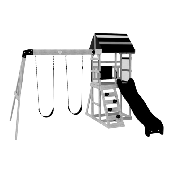
Bay Pointe
SWING SET
MODEL: # 2200128B
WARNING
Adult Assembly Required.
Not suitable for children under 36 months due to small parts.
FOR DOMESTIC USE ONLY. INTENDED FOR OUTDOOR USE.
For the most up to date assembly manual, to register your product, or to order replacement parts
Please visit www.backyarddiscovery.com
Para obtener instrucciones en español, visite www.backyarddiscovery.com
EASY STEP-BY-STEP
3D INTERACTIVE INSTRUCTIONS
DOWNLOAD THE FREE APP
INSTALLATION
SERVICES
AVAILABLE!
*
See inside for details
Made in China
INS-2200128B-A-BAY POINTE-ENG 8-24-22
Advertisement

Related Manuals for Backyard Discovery Bay Pointe


Summary of Contents for Backyard Discovery Bay Pointe
- Page 1 For the most up to date assembly manual, to register your product, or to order replacement parts Para obtener instrucciones en español, visite www.backyarddiscovery.com EASY STEP-BY-STEP INSTALLATION 3D INTERACTIVE INSTRUCTIONS SERVICES DOWNLOAD THE FREE APP AVAILABLE! See inside for details Made in China INS-2200128B-A-BAY POINTE-ENG 8-24-22...
- Page 2 Basic Setup Dimensions & Assembly Notes Owner's Manual Place the set on level ground, not less than 6'-7" [2 m] from any structure or obstruction such as a fence, garage, house, overhanging branches, laundry lines, or electrical wires. • While assembling unit, take time before and after each phase to make sure fort is level. If fort is not level, assembly will be difficult and improper assembly may result.
- Page 3 Parts Identification Owner's Manual Wood Components (Not to Scale) RIGHT FRONT UPRIGHT - W4L15660 1 3/8"x3 3/8"x75" (36x86x1905) POST ASSEMBLY - W2A02839 1 7/16"x3 3/8"x75" (36x86x1905) LEFT BACK UPRIGHT - W4L13210 1 3/8"x3 3/8"x75" (36x86x1905) RIGHT BACK UPRIGHT - W4L13211 1 3/8"x3 3/8"x75"...
- Page 4 Parts Identification Owner's Manual Wood Components (Not to Scale) GROUND RAIL - W4L13209 SAFETY RAIL - W4L13299 5/8"x3 3/8"x36 5/8" (16x86x930) 1"x2 3/8"x36 5/8" (24x60x930) GROUND RAIL - W4L13296 5/8"x3 3/8"x21 3/8" (16x86x542) FLOOR BOARD - W4L13223 5/8"x4 3/8"x33 3/4" (16x112x856) SLIDE BRACE - W4L13297 5/8"x3 3/8"x14 1/4"...
- Page 5 Parts Identification Owner's Manual Hardware Components H100021 BOLT WH 5/16x4 1/2 H100017 BOLT WH H100029 LAG SCREW WH 5/16x3 1/4 5/16x3 H100013 H100028 BOLT WH LAG SCREW WH (11) 5/16x2 1/4 5/16x2 1/2 H100012 BOLT WH H100027 LAG SCREW WH (20) (22) 5/16x2...
- Page 6 Parts Identification Owner's Manual Hardware Components H100090 SCREW PFH H100047 H100095 BOLT HEX (22) WASHER SPLIT 8x2 1/2" 5/16x2 3/4 5/16 H100111 SCREW PFH (13) H100044 BOLT HEX 5/16x2 H100108 WASHER LOCK INT 8x15 H100089 SCREW PFH (11) 8x1 3/4 H100042 BOLT HEX 5/16x1 1/4...
- Page 7 Parts Identification Owner's Manual Accessory Components (Not to Scale) 90° L-BRACKET - A4M01110 A4M01048 L BRACKET HAND GRIP A6P00314 A100153 L BRACKET 2.5x38x55x55 BLUE PLASTIC 66x66x127 BLUE AUGER GROUND A100178 BLUE HC ROCK A6P00040 BYD ID TAG STAKE A100175 (MEDIUM) AGES 3-10 "A"...
- Page 8 Parts Identification Owner's Manual Accessory Components (Not to Scale) A6P00402 6 FT SLIDE RAIL LEFT A6P00403 6 FT SLIDE RAIL RIGHT A6P00404 6 FT SLIDE BED A6P00410 PICKET PAL (x1) A6P00323 CHALK BOARD A6P00401 A6P00509 MESH PANEL ROOF TARP...
- Page 9 PRE-ASSEMBLY STEP 1 - SORTING PARTS It is critical for ease of assembly that you take the time to sort and organize the wood and hardware. WOOD PARTS: • Organize wood parts by the three-digit, alpha-numeric number stamped on each board (ex. P01). •...
- Page 10 PRE-ASSEMBLY STEP 2 - TOOLS REQUIRED Drill Attachments: Phillips Head Open End Wrenches 1/2" & 9/16" 1/8", 3/16", 3/8" & 7/16" Drill Bits 3/8" Drive Ratchet, 1/2" & 9/16" STD Sockets 1/2" & 9/16" Deep Sockets Phillips Screw Driver Cordless Drill or Electric Drill Rubber Mallet - Optional Claw Hammer...
- Page 11 PRE-ASSEMBLY STEP 3 - CHOOSE YOUR ASSEMBLY METHOD There are several types of assembly instructions available to you. 1. Printed Assembly Manual included with your set 2. BILT APP - 3D interactive instructions 3. Combination of the Printed Manual and BILT APP (Note: Step numbers can differ between the two methods)
- Page 12 STEP 1 LADDER ASSEMBLY H100072 T-NUT H100063 BOLT PTH WASHER A6P00040 H100108 BLUE HC ROCK #2 (x8) LADDER RUNG - W4L13286 (x4) (x8) LOCK INT 1/4x3/4 (x4) 5/8"x4 3/8"x16 7/8" (16x112x430) 8x15 (x4) LADDER RUNG (x4) BLUE HC ROCK #2 (x8) (x8) WASHER - 8x15...
- Page 13 STEP 2 LADDER ASSEMBLY LEFT RUNG ASSEMBLY (x2) H100086 SCREW PFH (x20) LADDER RUNG - W4L13285 8x1 1/2 5/8"x4 3/8"x16 7/8" (16x112x430) (x1) RIGHT RUNG ASSEMBLY (x2) UPRIGHT - W4L13283 1 7/16"x2 3/8"x43 3/4" (36x60x1111) (x1) UPRIGHT - W4L13284 1 7/16"x2 3/8"x43 3/4" (36x60x1111) (x1) (x1) TIP:...
- Page 14 STEP 1 SLIDE ASSEMBLY SLIDE BRACE - W4L13297 5/8"x3 3/8"x14 1/4" (16x86x362) A6P00404 6 FT SLIDE BED H100115 BOLT WH H100074 T-NUT 5/16x1/2 5/16 NOTE: TAKE NOTE OF SLIDE BED SURFACE FINISH, THE DULL SIDE WILL BE TOWARDS THE GROUND. PLACE SLIDE BRACE CENTERED ON THE BOTTOM (DULL SIDE) AND 1/2"...
- Page 15 STEP 2 SLIDE ASSEMBLY A6P00403 6 FT SLIDE RAIL RIGHT SLIDE BRACE - W4L13298 5/8"x3 3/8"x14 1/4" (16x86x362) A6P00402 6 FT SLIDE RAIL LEFT H100090 SCREW PFH (16) 8x2 1/2" NOTE: PLACE SECOND SLIDE RAIL ASSEMBLY OVER THE TOP OF THE SLIDE BED AND M78 CENTER SLIDE BRACES. INSERT THE SLIDE BED AND CENTER SLIDE BRACES INTO THE SLIDE CAVITY.
- Page 16 STEP 1 SWING BEAM A100153 L BRACKET 66x66x127 BLUE SWING BEAM SB74 SWING BEAM 2 POSITION - W4L13291 A4M00511 EXT. BRACKET 2"x5 1/4"x68 3/4" (50x134x1745) BLUE - LEFT SWING BEAM BYD ID TAG A4M00512 A100175 EXT BRACKET (MEDIUM) AGES 3-10 BLUE - RIGHT H100047 BOLT HEX...
- Page 17 STEP 2 SWING BEAM H100099 SWING HANGER H100110 NUT LOCK H100105 WASHER FLAT H100103 WASHER SAFETY 5/16x9 1/2 5/16 8x27 17x30 (x4) NUT - 5/16" (x4) WASHER - 8x27 (x4) WASHER - 17x30 (x4) SWING HANGER - 9 1/2"...
- Page 18 STEP 3 SWING BEAM ANGLE BRACE - W4L13293 1 3/8"x3 3/8"x72 7/8" (36x86x1850) END SUPPORT - W4L13294 SWING BEAM SUPPORT - W4L13292 1"x3 1/2"x39 1/2" (24x86x1000) 2"x3 3/8"x44 1/4" (50x86x1123) H100021 BOLT WH H100027 H100013 BOLT WH LAG SCREW WH H100005 NUT BARREL WH 5/16x4 1/2...
- Page 19 STEP 4 SWING BEAM SWING BEAM SUB ASSEMBLY (FROM STEP 2) H100011 BOLT WH H100005 NUT BARREL WH 5/16x1 3/4 5/16x7/8 'A' FRAME SUB ASSEMBLY (FROM STEP 3) (x2) BOLT - 1 3/4" (x2) NUT BARREL - 7/8"...
- Page 20 STEP 1 FORT ASSEMBLY FLOOR RAIL - W4L13295 GROUND RAIL - W4L13209 H100028 LAG SCREW WH 1"x3 3/8"x36 5/8" (24x86x930) 5/8"x3 3/8"x36 5/8" (16x86x930) 5/16x2 1/2 TOP RAIL - W4L13220 5/8"x2 3/8"x36 5/8" (16x60x930) H100027 LAG SCREW WH 5/16x2 RIGHT FRONT UPRIGHT - W4L15660 1 3/8"x3 3/8"x75"...
- Page 21 STEP 2 FORT ASSEMBLY LEFT BACK UPRIGHT - W4L13210 H100028 LAG SCREW WH 1 3/8"x3 3/8"x75" (36x86x1905) 5/16x2 1/2 RIGHT BACK UPRIGHT - W4L13211 H100027 LAG SCREW WH 1 3/8"x3 3/8"x75" (36x86x1905) 5/16x2 GROUND RAIL - W4L13215 FLOOR RAIL - W4L13212 5/8"x3 3/8"x36 5/8"...
- Page 22 STEP 3 FORT ASSEMBLY ANGLE GROUND RAIL - W4L13217 H100017 BOLT WH 5/8"x3 3/8"x65 5/8" (16x86x1666) H100074 T-NUT 5/16x3 1/4 5/16 SIDE RAIL - W4L13214 FLOOR RAIL - W4L13213 5/8"x2 3/8"x24 1/8" (16x60x612) 1"x3 3/8"x26" (24x86x660) H100012 BOLT WH 5/16x2 H100030 WASHER LOCK FLOOR SUPPORT - W4L13222...
- Page 23 STEP 4 FORT ASSEMBLY H100017 BOLT WH GROUND RAIL - W4L13216 FLOOR RAIL - W4L13213 H100074 T-NUT 5/16x3 1/4 5/8"x3 3/8"x25 3/8" (16x86x644) 1"x3 3/8"x26" (24x86x660) 5/16 FLOOR SUPPORT - W4L13222 H100012 BOLT WH 1"x3 3/8"x3 3/8" (24x86x86) 5/16x2 H100030 WASHER LOCK 8x19 (x1)
- Page 24 STEP 5 FORT ASSEMBLY H100090 SCREW PFH 8x2 1/2" FLOOR SUPPORT - W4L13289 FLOOR RAIL - W4L13221 15/16"x1 5/16"x17 1/4" (24x34x438) H100089 SCREW PFH 1"x3 3/8"x24 1/8" (24x86x612) (10) 8x1 3/4 A100314 "A" REVISION TAG H100128 SCREW PWH 8x5/8 (x2) (x2) SCREW - 5/8 (x10)
- Page 25 STEP 6 FORT ASSEMBLY H100027 LAG SCREW WH FLOOR BOARD - W4L13223 FLOOR BOARD - W4L13225 5/16x2 5/8"x4 3/8"x33 3/4" (16x112x856) 5/8"x4 3/8"x33 3/4" (16x112x856) H100030 WASHER LOCK 8x19 SIDE RAIL - W4L13218 H100086 SCREW PFH FLOOR BOARD - W4L13224 5/8"x2 3/8"x36 5/8"...
- Page 26 STEP 7 FORT ASSEMBLY H100013 BOLT WH H100128 SCREW PWH TOP RAIL - W4L13228 H100074 T-NUT 5/16x2 1/4 8x5/8 (10) 5/16 1"x5 1/4"x37" (24x134x940) SIDE RAIL - W4L13214 H100012 BOLT WH 5/8"x2 3/8"x24 1/8" (16x60x612) 5/16x2 H100030 WASHER LOCK (10) 8x19 A6P00401 MESH PANEL...
- Page 27 STEP 8 FORT ASSEMBLY H100013 BOLT WH H100128 SCREW PWH H100074 T-NUT 5/16x2 1/4 8x5/8 TOP RAIL - W4L13219 (10) 5/16 1"x5 1/4"x37" (24x134x940) H100012 BOLT WH SIDE RAIL - W4L13214 5/16x2 H100030 WASHER LOCK 5/8"x2 3/8"x24 1/8" (16x60x612) (10) 8x19 A6P00401 MESH PANEL...
- Page 28 STEP 9 FORT ASSEMBLY H100027 LAG SCREW WH H100029 LAG SCREW WH 5/16x3 5/16x2 H100010 BOLT WH 5/16x1-1/2 H100030 WASHER LOCK H100074 T-NUT 5/16 LADDER ASSEMBLY 8x19 (x1) T-NUT - 5/16" (x1) BOLT - 1 1/2" (x1) LAG SCREW - 3" LADDER ASSEMBLY (x3) WASHER - 8x19...
- Page 29 STEP 1 0 FORT ASSEMBLY GROUND RAIL - W4L13296 TOP LADDER RUNG - W4L13287 H100004 NUT BARREL WH 5/8"x3 3/8"x21 3/8" (16x86x542) H100027 LAG SCREW WH H100115 BOLT WH 5/8"x4 3/8"x16 7/8" (16x112x430) 5/16 x 5/8 5/16x2 5/16x1/2 A4M01048 L BRACKET 2.5x38x55x55 H100030 WASHER LOCK...
- Page 30 STEP 1 1 FORT ASSEMBLY H100088 SCREW PFH (16) 8x1 1/8 PICKET - W4L13281 PICKET - W4L13282 5/8"x2 3/8"x15 1/8" (16x60x385) 1"x2 3/8"x15 1/8" (24x60x385) H100121 SCREW PFH 8x3/4 (x8) SCREW - 8x3/4" 1 1/2" 1 1/2" 1 1/2" (x2) (x4) (x16) SCREW - 1 1/8"...
- Page 31 STEP 1 2 FORT ASSEMBLY H100392 SCREW PWH BLK 8x3/4 A6P00323 CHALK BOARD (x1) CHALK BOARD (x6) SCREW - 3/4"...
- Page 32 STEP 13 FORT ASSEMBLY UPRIGHT - W4L13226 1"x2"x36" (24x52x914) H100010 BOLT WH H100115 BOLT WH H100005 NUT BARREL WH 5/16x1-1/2 5/16x1/2 5/16x7/8 A4M01048 L BRACKET H100031 WASHER LOCK H100030 WASHER LOCK H100145 LAG SCREW WH H100074 T-NUT 2.5x38x55x55 1/4x1 1/2 5/16 8x19 12x19...
- Page 33 STEP 14 FORT ASSEMBLY H100649 LAG SCREW WH H100010 BOLT WH 1/4x2 1/2 5/16x1-1/2 ANGLE BRACE - W4L13288 15/16"x3 3/8"x40 1/16" (24x86x1018) H100138 WASHER LOCK H100030 WASHER LOCK H100074 T-NUT 5/16 6x15 8x19 (x1) LAG SCREW - 2 1/2" (x1) WASHER - 6x15 (x1) (x1)
- Page 34 STEP 15 FORT ASSEMBLY H100137 BOLT WH H100490 BOLT WH H100136 NUT BARREL WH 1/4x1 1/4x5/8 1/4x5/8 TOP RAIL - W4L13227 1"x3 3/8"x36 5/8" (24x86x930) 90° L-BRACKET - A4M01110 H100111 SCREW PFH H100139 WASHER LOCK H100072 T-NUT 8x15 (x8) SCREW - 2" (x4) 90°...
- Page 35 STEP 16 FORT ASSEMBLY TOP RAIL - W4L13280 5/8"x2 3/8"x36 5/8" (16x60x930) H100030 WASHER LOCK H100010 BOLT WH H100074 T-NUT 5/16x1-1/2 5/16 8x19 TOP RAIL - W4L13229 5/8"x2 3/8"x21 1/8" (16x60x538) A4M01110 90° L-BRACKET - H100141 BOLT WH H100490 BOLT WH H100136 NUT BARREL WH 1/4 x 1/2"...
- Page 36 STEP 17 FORT ASSEMBLY H100649 LAG SCREW WH H100138 WASHER LOCK ANGLE BRACE - W4L13290 1/4x2 1/2 15/16"x3 3/8"x11 13/16" (24x86x300) 6x15 (x2) LAG SCREW - 2 1/2" (x2) WASHER - 6x15 (x2)
- Page 37 STEP 18 FORT ASSEMBLY H100044 BOLT HEX H100042 BOLT HEX 5/16x2 5/16x1 1/4 H100095 WASHER SPLIT SWING BEAM ASSEMBLY H100074 T-NUT H100105 WASHER FLAT 5/16 5/16 8x27 (x4) (x4) WASHER - 8x27 T-NUT - 5/16" (x4) WASHER - 5/16" (x2) BOLT HEX - 2"...
- Page 38 STEP 19 FORT ASSEMBLY H100070 SCREW PWH (10) 8x3/4 A6P00509 ROOF TARP (x1) ROOF TARP (x10) SCREW - 8x3/4"...
- Page 39 STEP 20 FORT ASSEMBLY A6P00405 ROPE-CHAIN B / SEAT B (x2) SWING ASSEMBLY NOTE: WHEN HANGING YOUR SWINGS, IT IS REQUIRED TO ONLY TRIM AROUND THE SPECIFIC CHAIN LOOP THAT ALLOWS THE BOTTOM OF THE SWING SEAT, (WHEN SETTING ON IT) TO BE NO LOWER THAN (35cm) 13-7/8 INCHES FROM THE GROUND.
- Page 40 STEP 21 FORT ASSEMBLY H100138 WASHER LOCK H100145 LAG SCREW WH 1/4x1 1/2 6x15 HAND GRIP A6P00314 H100142 BOLT WH H100072 T-NUT BLUE PLASTIC 1/4x1-1/4 (x2) T-NUT - 1/4" (x4) WASHER - 6x15 (x2) BOLT WH - 1-1/4" (x2) HAND GRIP BLUE PLASTIC (x2) LAG SCREW - 1 1/2"...
- Page 41 STEP 22 FORT ASSEMBLY H100009 BOLT WH H100222 BOLT WH 5/16x1 1/4 5/16x3/4 H100031 WASHER LOCK 12x19 A100178 AUGER GROUND STAKE NUT BARREL WH H100004 H100005 NUT BARREL WH 5/16 x 5/8 5/16x7/8 NOTE: TWIST GROUND STAKES INTO GROUND IN LOCATIONS SHOWN. USING GROUND STAKE AS A GUIDE, DRILL 7/16"...
- Page 42 STEP 23 FORT ASSEMBLY H100115 BOLT WH H100074 T-NUT 9208018 SLIDE 5/16x1/2 5/16 ASSEMBLY NOTE: 7 1/8 4 3/8 CENTER SLIDE IN OPENING. USING DIMENSIONS SHOWN AS A TEMPLATE, DRILL (2) 3/8" HOLES THROUGH SLIDE & DECK FOR HARDWARE. 4 1/8 (x2) BOLT - 1/2"...
- Page 43 STEP 24 FORT ASSEMBLY H100111 SCREW PFH SAFETY RAIL - W4L13299 1"x2 3/8"x36 5/8" (24x60x930) (x4) SCREW - 2" (x1)
Need help?
Do you have a question about the Bay Pointe and is the answer not in the manual?
Questions and answers