Advertisement
Quick Links
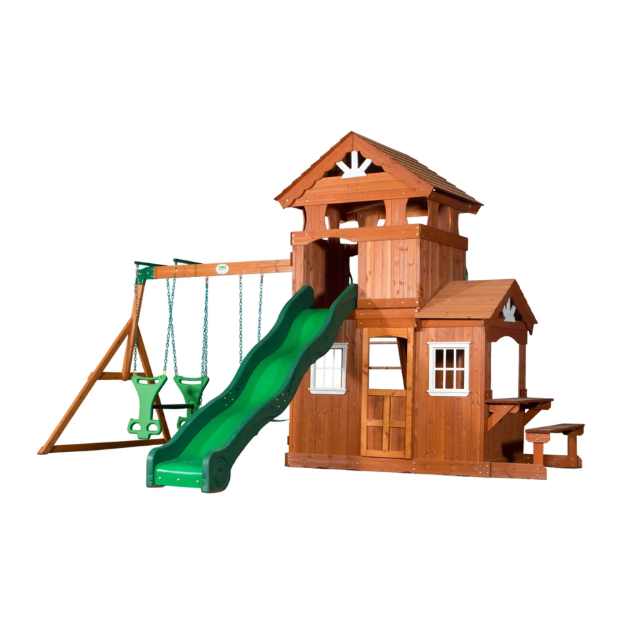
Shenandoah
to register your set, or to order replacement parts please visit
SAVE THIS ASSEMBLY MANUAL FOR FUTURE REFERENCE IN THE EVENT THAT
YOU NEED TO ORDER REPLACEMENT PARTS.
Wooden Swing Set
Model # 65413
Owner's Manual & Assembly Instructions
average 2 person assembly time
assembly time may vary based on skill level
For the most up to date assembly manual,
www.backyarddiscovery.com
MANUFACTURED BY:
Backyard Discovery
3305 Airport Drive
Pittsburg, KS 66762
800-856-4445
Advertisement

Related Manuals for Backyard Discovery Shenandoah 65413


Summary of Contents for Backyard Discovery Shenandoah 65413
- Page 1 MANUFACTURED BY: Shenandoah Wooden Swing Set Backyard Discovery 3305 Airport Drive Pittsburg, KS 66762 Model # 65413 Owner's Manual & Assembly Instructions 800-856-4445 average 2 person assembly time assembly time may vary based on skill level For the most up to date assembly manual, to register your set, or to order replacement parts please visit www.backyarddiscovery.com...
- Page 2 STOP PARE Missing A Part? CALL US BEFORE GOING BACK TO THE STORE! The store where you made your purchase does not stock parts for this item. If you have assembly questions or if you need parts, whether they are missing or damaged Call Toll-Free Help Line or visit www.swingsetsonline.com 1-800-856-4445 PLEASE READ THIS BEFORE STARTING ASSEMBLY...
- Page 3 Owner’s Manual Play Set Dear Customer: Please read entire booklet completely before beginning the assembly process. Equipment is recommended for use by children 3 to 10 years of age. Structures are not intended for public use. The Company does not warranty any of its residential structures subjected to commercial use such as: Daycare, Preschool, Nursery School, Recreational Park, or any similar Commercial Application.
- Page 4 Owner’s Manual Play Set Please refer to the Assembly section of the Assembly Manual for Maximum Fall Height Positioning Your Playcenter 1. The Playcenter is designed to be installed on a level surface by an Adult with an Adult helper. Place in a flat area of your yard to minimize ground preparation. 2.
- Page 5 Owner’s Manual Play Set The following chart explains the fall height in feet from which a life threatening head injury would not be expected Critical Heights in feet (m) of Tested Materials Material Uncompressed Depth Compressed Depth 6" (152mm) 9" (228mm) 12"...
- Page 6 Owner’s Manual Play Set 18. Verify that any suspended climbing ropes, chain, or cable are secured at both ends and that they cannot be looped back on it. 19. Instruct children not to attach items to the playground equipment that are not specifically designed for use with the equipment, such as, but not limited to, jump ropes, clothesline, pet leashes, cables and chain as they may cause a strangulation hazard.
- Page 7 Third Party Assembly: Customer may, in their sole discretion, elect to use a third party person or service to assemble this product. Backyard Discovery assumes no responsibility or liability for any charge incurred by the Customer for any assembly services’.
- Page 8 Owner’s Manual Play Set APPENDIX A Information on Playground Surfacing Materials: The following information is from the United States Consumer Product Safety Commission’s Information Sheet for playground surfacing material; also see the following website for additional information: www.cpsc.gov/cpscpub/pubs/323.html. Rev5/09/12...
- Page 9 Owner’s Manual Play Set Rev5/09/12...
- Page 10 The stakes provided should be used to secure it firmly to the ground. 2. What size area is recommended for the playset? Backyard Discovery recommends at least a 6’ (six foot) perimeter around and above the playset for maximum safety. 3. What age range is appropriate for the playsets? Backyard Discovery playsets are recommended for children ages 3 –...
- Page 11 11. The end beam is not straight up and down. Why not? This is normal. Backyard Discovery designs playsets this way to ensure the strongest structure possible. The slight angle adds strength and reduces rocking and twisting.
- Page 12 Tools Required for Installation: (These are the tools that are generally required for assembly of our outdoor products. These tools are not included with the outdoor product purchase.) (Square) (Level 24") (Phillips Screw Driver) (Open End Wrenches 1/2") (Tape Measure) (Drill Attachments: Phillips Head) (Cordless Drill or Electric Drill)
- Page 13 Basic Setup Dimensions Place the set on level ground, not less than 6 ft [2 m] from any structure or obstruction such as a fence, garage, house, overhanging branches, laundry lines, or electrical wires. Safe Play Zone General Information: Safe play height: 10'- 5 1/16" [3.2 m] Maximum fall height: 6'-3 5/8"...
- Page 14 Parts Identification Wood Components (NOT TO SCALE) E1 - UPRIGHT - W104109 1 3/8"x3 3/8"x55 5/8" (36x86x1414) E2 - UPRIGHT - W104101 1 3/8"x3 3/8"x89 1/2" (36x86x2272) E3 - UPRIGHT - W104102 1 3/8"x3 3/8"x89 1/2" (36x86x2272) E4 - UPRIGHT - W104103 1 3/8"x3 3/8"x89 1/2"...
- Page 15 Parts Identification Wood Components (NOT TO SCALE) G3 - LEMONADE GABLE BOARD - W104151 1"x5 1/4"x29 7/8" (24x134x758) G4 - FORT GABLE BOARD - W104150 1"x5 1/4"x39 7/8" (24x134x1014) G5 - SHELF BOARD - W104178 1"x5 1/4"x43" (24x134x1092) G6 - SHELF BOARD - W104179 1"x5 1/4"x43"...
- Page 16 Parts Identification Wood Components (NOT TO SCALE) H3 - SHELF SUPPORT - W104176 1"x3 3/8"x10 1/4" (24x86x260) H4 - SHELF SUPPORT - W104163 1"x3 3/8"x10 1/2" (24x86x268) H5 - FLOOR RAIL - W104113 1"x3 3/8"x44 1/4" (24x86x1124) H6 - HORIZONTAL ROOF SUPPORT - W104145 1"x3 3/8"x44 1/4"...
- Page 17 Parts Identification Wood Components (NOT TO SCALE) H77 - LEFT UPRIGHT - W100972 1"x3 3/8"x64 3/8" (24x86x1634) H78 - RIGHT UPRIGHT - W100973 1"x3 3/8"x64 3/8" (24x86x1634) H79 - END SUPPORT - W100992 1"x3 1/2"x42" (24x86x1072) H80 - GROUND BOARD - W100990 1"x3 3/8"x87 3/8"...
- Page 18 Parts Identification Wood Components (NOT TO SCALE) M5 - UPPER WALL BOARD - W104132 5/8"x3 3/8"x8 1/2" (16x86x216) M6 - UPPER WALL BOARD - W104128 5/8"x3 3/8"x11 7/8" (16x86x302) M7 - UPPER WALL BOARD - W104129 5/8"x3 3/8"x11 7/8" (16x86x302) M8 - WALL SLAT - W104134 5/8"x3 3/8"x14 7/8"...
- Page 19 Parts Identification Wood Components (NOT TO SCALE) M18 - ENTRANCE WALL BOARD - W104141 5/8"x3 3/8"x27 7/8" (16x86x708) M19 - LOWER WALL BOARD - W104126 5/8"x3 3/8"x29 5/8" (16x86x754) M20 - LOWER WALL BOARD - W104127 5/8"x3 3/8"x29 5/8" (16x86x754) M21 - GABLE BOARD - W104158 5/8"x3 3/8"x39 3/8"...
- Page 20 Parts Identification Wood Components (NOT TO SCALE) M73 - REAR SUPPORT - W100610 5/8"x3 3/8"x19 1/4" (16x86x488) M74 - ROCK WALL BOARD - W100987 5/8"x3 3/8"x26 5/8" (16x86x675) M75 - ROCK WALL BOARD - W100988 5/8"x3 3/8"x26 5/8" (16x86x675) M76 - ROCK WALL BOARD - W100989 5/8"x3 3/8"x26 5/8"...
- Page 21 Parts Identification Wood Components (NOT TO SCALE) U1 - WALL RAIL - W104147 3/4"x5 1/4"x37 3/8" (20x134x950) W71 - SWING BEAM SUPPORT - W102420 2"x3 3/8"x49 5/8" (50x86x1260) (3) FP1 - FLOOR PANEL - W104121 (2) RP1 - ROOF PANEL - W104148 (1) RP3 - ROOF PANEL - W104152 (2) RP2 - ROOF PANEL - W104149 (1) RP5 - ROOF PANEL - W104154...
- Page 22 Parts Identification Hardware (27) F - BOLT WH 5/16x1 - H100008 CM - BOLT WH 5/16x1/2 - H100115 G - BOLT WH 5/16x1 1/4 - H100009 (22) B - NUT BARREL WH 5/16x5/8 - H100004 (46) H - BOLT WH 5/16x1 1/2 - H100010 (93) D - NUT BARREL WH 5/16x7/8 - H100005 J - BOLT WH 5/16x1 3/4 - H100011...
- Page 23 Parts Identification Hardware - SCREW PFH 6x3/4 - H100084 (166) - WASHER LOCK EXT 8x19 - H100030 (2) - SCREW PFH 8x1/2 - H100124 (296) - SCREW PFH 8x1-1/8" - H100088 (115) - WASHER LOCK EXT 12x19 - H100031 (222) - SCREW PFH 8x1-1/2" - H100086 (7) - SCREW PFH 8x1-3/4"...
- Page 24 Parts Identification Hardware (26) AZ - BOLT PTH 1/4x1 1/4 - H100062 KS - NUT BARREL WH 1/4x5/8 - H100136 KT - BOLT WH 1/4x1 - H100137 LC - LAG SCREW WH 1/4x1-1/2 - H100145 AJ - BOLT HEX 5/16x1 1/4 - H100042 YK - BOLT WH 5/16x3/4 - H100222 AN - BOLT HEX 5/16x2-3/4 - H100047...
- Page 25 Parts Identification Accessories (NOT TO SCALE) DR - SLIDE RAIL 10' BOTTOM LEFT GREEN - A100030 DS - SLIDE RAIL 10' BOTTOM RIGHT GREEN - A100031 DT - SLIDE RAIL 10' TOP LEFT GREEN - A100032 TR - SLIDE RAIL 10' TOP RIGHT GREEN - A100033 DW - SLIDE SUPPORT TUBE 21.34x505 - A100034 DX - SLIDE BED 10' LIGHT GREEN - A100035...
- Page 26 Parts Identification Accessories (NOT TO SCALE) DN - GLIDER SEAT DARK GREEN - A100025 VB - PLASTIC SUNBURST - A100361 DP - SWING SEAT GREEN - A100027 DJ - GLIDER ARM LIGHT GREEN - A100021 WR - LARGE PLASTIC WINDOW TRIM - A100365 SX - PLASTIC WINDOW 44x412x485 - A100321 (1) JX - STOVE ASSEMBLY - A6P00025 (1) JR - FAUCET KIT - A6P00024...
- Page 27 Parts Identification Accessories (NOT TO SCALE) (1) - "A" REVISION TAG - A100314 (1) - BYD ID TAG (LARGE) AGES 3-10 - A100164 - L BRACKET 66x66x127 - A100140 (12) - CLIMBING ROCK - GREEN - A100064 (8) - QUICK LINK - A100069 (2) - L BRACKET 2.5x38x50x55 - A100340 (4) - TUBING CAP GLIDER SUPPORT - A100067 (4) - GLIDER BUSHING BYD GREEN - A100066...
- Page 28 H76 - LADDER RUNG - W100611 H77 - LEFT UPRIGHT - W100972 1"x3 3/8"x18 1/8" (24x86x460) 1"x3 3/8"x64 3/8" (24x86x1634) 5 FOOT LADDER ASSEMBLY STEP 1 SCREW PFH (10)
- Page 29 H78 - RIGHT UPRIGHT - W100973 1"x3 3/8"x64 3/8" (24x86x1634) 5 FOOT LADDER ASSEMBLY STEP 2 SCREW PFH (10)
- Page 30 M73 - REAR SUPPORT - W100610 M107 - ATTACHMENT BOARD - W103559 5/8"x3 3/8"x19 1/4" (16x86x488) 5/8"x3 3/8"x19 1/4" (16x86x488) 5 FOOT LADDER ASSEMBLY STEP 3 SCREW PFH...
- Page 31 JV - HAND GRIP GREEN 816 c/c - A100134 5 FOOT LADDER ASSEMBLY STEP 4 LAG SCREW WH 1/4x1-1/2...
- Page 32 E72 - LEFT RAIL - W100036 E73 - RIGHT RAIL - W100037 1 3/8"x3 3/8"x61 3/4" (36x86x1570) 1 3/8"x3 3/8"x61 3/4" (36x86x1570) M74 - ROCK WALL BOARD - W100987 M75 - ROCK WALL BOARD - W100988 M76 - ROCK WALL BOARD - W100989 5/8"x3 3/8"x26 5/8"...
- Page 33 M108 - TOP BOARD - W103105 5/8"x3 3/8"x27 7/8" (16x86x707) STEP 2 USING M108 AS A GUIDE, PRE-DRILL TOP EDGE OF RAILS WITH 1/8" DRILL BIT. FAILURE TO PRE-DRILL MAY RESULT IN BOARD SPLITTING. ATTACH M108 ROCK WALL END BOARD TO E72 & E73 RAILS USING 1 1/2" SCREWS. SCREW PFH 8x1 1/2 SCREW PFH 8x1 1/2...
- Page 34 EV - CLIMBING ROCK - GREEN - A100064 STEP 3 ATTACH EV ROCKS TO BOARDS USING 1/4"X1 1/4" BOLTS, LOCK WASHERS, AND 1/4" T-NUTS. BOLT PTH (24) 1/4x1 1/4 WASHER (24) LOCK INT 8x15 (24) T-NUT 1/4 BOLT PTH 1/4x1 1/4 WASHER LOCK INT 8x15 T-NUT 1/4...
- Page 35 M70 - SLIDE BED SUPPORT - W100935 DX - SLIDE BED 10' LIGHT GREEN - A100035 5/8"x3 3/8"x19 7/8" (16x86x505) 10 FOOT SLIDE ASSEMBLY PHASE 1 STEP 1 BOLT WH 5/16x1/2 ATTACH SLIDE BED SUPPORT TO SLIDE USING HARDWARE SHOWN. WASHER LOCK EXT 12x19...
- Page 36 DS - SLIDE RAIL 10' BOTTOM RIGHT GREEN - A100031 TR - SLIDE RAIL 10' TOP RIGHT GREEN - A100033 DR - SLIDE RAIL 10' BOTTOM LEFT GREEN - A100030 DT - SLIDE RAIL 10' TOP LEFT GREEN - A100032 10 FOOT SLIDE ASSEMBLY PHASE 2 STEP 2...
- Page 37 DW - SLIDE SUPPORT TUBE 21.34x505 - A100034 21.34 OD x 2.77 W x 505 10 FOOT SLIDE ASSEMBLY PHASE 3 STEP 3 PLACE (1) SLIDE RAIL ASSEMBLY ON A FLAT SURFACE AND BEGIN INSERTING SLIDE BED AT THE BOTTOM OF THE SLIDE RAIL (FIG. 1). HAVE A HELPER BEND THE SLIDE BED TOWARDS THE TOP OF THE SLIDE AND INSERT THE BED INTO THE SLIDE CAVITY.
- Page 38 10 FOOT SLIDE ASSEMBLY PHASE 4 STEP 4 ONCE THE SLIDE BED, SUPPORT TUBES, AND SUPPORT BOARD ARE COMPLETELY IN THE CAVITY AND SUPPORT POCKET, SECURE USING 3" SCREWS AT EACH OF THE PILOT HOLE LOCATIONS AS SHOWN. REPEAT PROCESS FOR OPPOSITE SLIDE RAIL. SCREW PFH (38) SCREW PFH 8x3...
- Page 39 SB74 - SWING BEAM EXTENDED - W102419 2"x5 1/4"x89 1/2" (50x134x2274) GD - L BRACKET 66x66x127 - A100140 TC - SWING BEAM EXTENSION BRACKET-RIGHT - A100326 TB - SWING BEAM EXTENSION BRACKET-LEFT - A100325 4 FT GREEN EXTENDED SWING BEAM WITH GLIDER BOLT WH 5/16x1-3/4 BOLT HEX...
- Page 40 E77 - ANGLE BRACE - W100991 W71 - SWING BEAM SUPPORT - W102420 1 3/8"x3 3/8"x74 3/8" (36x86x1890) 2"x3 3/8"x49 5/8" (50x86x1260) H79 - END SUPPORT - W100992 H80 - GROUND BOARD - W100990 1"x3 1/2"x42" (24x86x1072) 1"x3 3/8"x87 3/8" (24x86x2218) STEP 2 ATTACH H80 GROUND BOARD TO (2) E77 ANGLED SUPPORT BOARDS USING (2) 2"...
- Page 41 STEP 3 INSERT W71 BOARD INTO TB AND TC BRACKET OPENING AND SECURE USING (2) 1-3/4" BOLTS AND 7/8" BARREL NUTS, AS SHOWN. BOLT WH INSERT (2) 2-1/2" BOLTS, LOCK WASHERS AND 1-1/2" BARREL NUTS INTO THE EDGE OF 5/16x1-3/4 BOLT WH W71 BOARD, AS SHOWN.
- Page 42 EY - TUBING CAP GLIDER SUPPORT - A100067 EX - GLIDER BUSHING BYD GREEN - A100066 EW - GLIDER SUPPORT BYD GREEN - A100065 STEP 4 ATTACH (2) EW GLIDER SUPPORT BARS TO SB74 SWING BEAM USING (2) 5-3/4" BOLTS, FLAT WASHERS AND 5/16"...
- Page 43 STEP 5 INSERT (4) SWING HANGER QUICK LINK INTO SB74 SWING BEAM USING (4) SAFETY NUT LOCK 5/16 WASHERS, FLAT WASHERS AND 5/16" LOCK NUTS, AS SHOWN. WASHER FLAT 8x27 WASHER SAFETY 17x30 SWING HANGER QUICK LINK...
- Page 44 STEP 1 LAY PARTS FLAT ON GROUND AND INSERT T-NUTS USING A HAMMER. T-NUT 5/16 (16) T-NUT 5/16 T-NUT 5/16 T-NUT 5/16 T-NUT 5/16 T-NUT 5/16 NOTE HOLE LOCATION FOR ORIENTATION.
- Page 45 E2 - UPRIGHT - W104101 G8 - SWING BEAM MOUNTING BOARD - W104119 1 3/8"x3 3/8"x89 1/2" (36x86x2272) 1"x5 1/4"x44 1/4" (24x134x1124) E3 - UPRIGHT - W104102 M25 - WALL RAIL - W104162 G11 - GROUND BOARD - W104107 1 3/8"x3 3/8"x89 1/2" (36x86x2272) 5/8"x3 3/8"x44 1/4"...
- Page 46 G12 - GROUND BOARD - W104105 1"x5 1/4"x82" (24x134x2084) G13 - GROUND BOARD - W104106 1"x5 1/4"x82" (24x134x2084) STEP 3 WASHER LOCK EXT 8x19 LAG SCREW WH 5/16x2 1/2 WASHER LOCK EXT 8x19 LAG SCREW WH 5/16x2 1/2 WASHER LOCK EXT 8x19 LAG SCREW WH 5/16x2 1/2...
- Page 47 E4 - UPRIGHT - W104103 1 3/8"x3 3/8"x89 1/2" (36x86x2272) E5 - UPRIGHT - W104104 1 3/8"x3 3/8"x89 1/2" (36x86x2272) STEP 4 WASHER LOCK EXT 8x19 LAG SCREW WH 5/16x2 1/2 WASHER LOCK EXT 8x19 LAG SCREW WH 5/16x2 1/2 LAG SCREW WH 5/16x2 1/2 WASHER LOCK EXT 8x19...
- Page 48 E1 - UPRIGHT - W104109 1 3/8"x3 3/8"x55 5/8" (36x86x1414) STEP 5 WASHER LOCK EXT 8x19 LAG SCREW WH 5/16x2 1/2 WASHER LOCK EXT 8x19 LAG SCREW WH 5/16x2 1/2 LAG SCREW WH 5/16x2 1/2 WASHER LOCK EXT 8x19...
- Page 49 G7 - GROUND BOARD - W104108 1"x5 1/4"x44 1/4" (24x134x1124) STEP 6 WASHER LOCK EXT 8x19 BOLT WH 5/16x2 WASHER LOCK EXT 12x19 NUT BARREL WH 5/16x7/8 WASHER LOCK EXT 12x19 NUT BARREL WH 5/16x7/8 WASHER LOCK EXT 8x19 BOLT WH 5/16x2...
- Page 50 H5 - FLOOR RAIL - W104113 1"x3 3/8"x44 1/4" (24x86x1124) STEP 7 WASHER LOCK EXT 8x19 BOLT WH 5/16x2 1/4 WASHER LOCK EXT 8x19 BOLT WH 5/16x2 1/4...
- Page 51 H11 - FLOOR RAIL - W104110 1"x3 3/8"x53 7/8" (24x86x1370) H12 - FLOOR RAIL - W104111 1"x3 3/8"x53 7/8" (24x86x1370) STEP 8 WASHER LOCK EXT 8x19 WASHER LOCK EXT 8x19 LAG SCREW WH 5/16x2 1/2 LAG SCREW WH 5/16x2 1/2 WASHER LOCK EXT 8x19 LAG SCREW WH 5/16x2 1/2...
- Page 52 H10 - FLOOR SUPPORT - W104120 1"x3 3/8"x51 5/8" (24x86x1310) STEP 9 SCREW PFH 8x2 1/2 SCREW PFH 8x2 1/2 SCREW PFH 8x2 1/2...
- Page 53 U1 - WALL RAIL - W104147 3/4"x5 1/4"x37 3/8" (20x134x950) STEP 10 WASHER LOCK EXT 12x19 BOLT WH 5/16x1 1/4 WASHER LOCK EXT 8x19 NUT BARREL WH 5/16x7/8 WASHER LOCK EXT 12x19 NUT BARREL WH 5/16x7/8 WASHER LOCK EXT 8x19 BOLT WH 5/16x1 1/4...
- Page 54 F71 - STANDARD ANGLE BRACE - W100689 1 3/8"x2 3/8"x13" (36x60x330) STEP 11 LAG SCREW BOLT WH WH 5/16x2 5/16x2 1/4 WASHER LOCK EXT 8x19 BOLT WH 5/16x2 1/4 WASHER LOCK EXT 8x19 WASHER LOCK EXT 8x19 LAG SCREW WH 5/16x2...
- Page 55 F71 - STANDARD ANGLE BRACE - W100689 1 3/8"x2 3/8"x13" (36x60x330) STEP 12 BOLT WH 5/16x2 LAG SCREW WH 5/16x2 1/2 WASHER LOCK EXT WASHER 12x19 LOCK EXT 8x19 NUT BARREL WH 5/16x7/8 NUT BARREL WH 5/16x7/8 WASHER LOCK EXT 12x19 BOLT WH 5/16x2 LAG SCREW WH 5/16x2 1/2 WASHER LOCK EXT 8x19...
- Page 56 N2 - FLOOR BOARD - W104122 5/8"x2 3/8"x37 3/8" (16x60x950) (3) FP1 - FLOOR PANEL - W104121 STEP 13 SCREW PFH (65) 8x1 1/2 SCREW PFH 8x1 1/2...
- Page 57 K1 - UPPER WALL RAIL - W104116 5/8"x5 1/4"x45 1/2" (16x134x1156) STEP 14 WASHER LOCK EXT 12x19 NUT BARREL WH 5/16x7/8 BOLT WH WASHER LOCK EXT 8x19 5/16x1 1/2 WASHER LOCK EXT 8x19 BOLT WH 5/16x1 1/2 WASHER NUT BARREL LOCK EXT WH 5/16x7/8 12x19...
- Page 58 K2 - ARCH BOARD - W104117 5/8"x5 1/4"x53 7/8" (16x134x1370) K3 - DOUBLE ARCH BOARD - W104118 5/8"x5 1/4"x53 7/8" (16x134x1370) STEP 15 LAG SCREW LAG SCREW WH 5/16x2 WH 5/16x2 WASHER LOCK EXT 8x19 WASHER LOCK EXT 8x19...
- Page 59 M24 - WALL RAIL - W104133 5/8"x3 3/8"x44 1/4" (16x86x1124) STEP 16 WASHER LOCK EXT 8x19 BOLT WH 5/16x1 1/2 WASHER LOCK EXT 12x19 NUT BARREL WH 5/16x7/8 NUT BARREL WH 5/16x7/8 WASHER LOCK EXT 12x19 WASHER LOCK EXT 8x19 BOLT WH 5/16x1 1/2...
- Page 60 M12 - WALL RAIL - W104136 M2 - SMALL WALL RAIL - W104135 5/8"x3 3/8"x25 1/4" (16x86x642) 5/8"x3 3/8"x5 3/8" (16x86x138) STEP 17 LAG SCREW WH 5/16x2 WASHER LOCK EXT 8x19 LAG SCREW WH 5/16x2 LAG SCREW WH 5/16x2 WASHER LOCK EXT 8x19 WASHER LOCK EXT 8x19...
- Page 61 M27 - WALL RAIL - W104115 5/8"x3 3/8"x50 1/2" (16x86x1283) STEP 18 LAG SCREW WH 5/16x2 1/2 WASHER LOCK EXT 8x19 LAG SCREW WH 5/16x2 1/2 WASHER LOCK EXT 8x19 WASHER LOCK EXT 8x19 LAG SCREW WH 5/16x2 1/2...
- Page 62 M16 - LEMONADE ROOF SUPPORT - W104123 5/8"x3 3/8"x26 3/4" (16x86x678) STEP 19 LAG SCREW WH 5/16x2 WASHER LOCK EXT 8x19 WASHER LOCK EXT 8x19 WASHER LOCK EXT 8x19 LAG SCREW WH 5/16x2 LAG SCREW WH 5/16x2...
- Page 63 G10 - LEMONADE ARCH BOARD - W104175 1"x5 1/4"x44 1/4" (24x134x1124) STEP 20 SCREW PFH 8x2 SCREW PFH...
- Page 64 H14 - DOOR RAIL - W104114 1"x3 3/8"x59" (24x86x1500) STEP 21 WASHER BOLT WH LOCK EXT 5/16x1 8x19 BOLT WH 5/16x1 1/2 WASHER NUT BARREL LOCK EXT WH 5/16x7/8 12x19 WASHER LOCK EXT 8x19 BOLT WH 5/16x1 1/2 BOLT WH 5/16x1 WASHER LOCK EXT 8x19 WASHER LOCK EXT 12x19 NUT BARREL WH 5/16x7/8...
- Page 65 M8 - WALL SLAT - W104134 5/8"x3 3/8"x14 7/8" (16x86x378) STEP 22 SCREW PFH 8x1 1/8 SCREW PFH (24) 8x1 1/8 SCREW PFH 8x1 1/8 REFERENCE VIEW...
- Page 66 M22 - LONG ROOF SUPPORT - W104139 5/8"x3 3/8"x43 1/4" (16x86x1098) STEP 23 WASHER LOCK EXT BOLT WH 8x19 5/16x1 WASHER NUT BARREL LOCK EXT WH 5/16x5/8 12x19 WASHER LOCK EXT 8x19 BOLT WH 5/16x1 WASHER LOCK EXT 12x19 NUT BARREL WH 5/16x5/8...
- Page 67 M23 - LONG ARCH ROOF SUPPORT - W104140 5/8"x3 3/8"x43 1/4" (16x86x1098) STEP 24 SCREW PFH 8x1 1/8 SCREW PFH 8x1 1/8...
- Page 68 M13 - WALL BOARD - W104137 5/8"x3 3/8"x26 1/8" (16x86x662) STEP 25 SCREW PFH 8x1 1/8 SCREW PFH (12) 8x1 1/8 SCREW PFH 8x1 1/8 REFERENCE VIEW...
- Page 69 M13 - WALL BOARD - W104137 5/8"x3 3/8"x26 1/8" (16x86x662) STEP 26 SCREW PFH 8x1 1/8 SCREW PFH 8x1 1/8 SCREW PFH 8x1 1/8 REFERENCE VIEW...
- Page 70 M22 - LONG ROOF SUPPORT - W104139 5/8"x3 3/8"x43 1/4" (16x86x1098) STEP 27 WASHER WASHER LOCK EXT 12x19 LOCK EXT 8x19 BOLT WH 5/16x1 NUT BARREL WH 5/16x5/8 NUT BARREL WH 5/16x5/8 WASHER LOCK EXT 12x19 BOLT WH 5/16x1 WASHER LOCK EXT 8x19 WASHER LOCK EXT 12x19 NUT BARREL WH 5/16x5/8 WASHER LOCK EXT 8x19...
- Page 71 M23 - LONG ARCH ROOF SUPPORT - W104140 5/8"x3 3/8"x43 1/4" (16x86x1098) STEP 28 SCREW PFH 8x1 1/8 SCREW PFH 8x1 1/8...
- Page 72 M13 - WALL BOARD - W104137 M14 - WALL BOARD - W104138 5/8"x3 3/8"x26 1/8" (16x86x662) 5/8"x3 3/8"x26 1/8" (16x86x662) STEP 29 SCREW PFH 8x1 1/8 SCREW PFH (18) 8x1 1/8 SCREW PFH 8x1 1/8 REFERENCE VIEW...
- Page 73 TZ - L BRACKET 2.5x38x50x55 - A100340 STEP 30 WASHER LOCK EXT NUT BARREL WH 5/16x7/8 12x19 SCREW TAPPING BOLT WH WASHER LOCK EXT 12x19 14x5/8 5/16x1 NUT BARREL WH 5/16x7/8 SCREW TAPPING 14x5/8 BOLT WH 5/16x1...
- Page 74 M9 - SHORT ROOF SUPPORT - W104143 5/8"x3 3/8"x15 5/8" (16x86x398) STEP 31 WASHER LOCK EXT BOLT WH WASHER LOCK EXT 8x19 8x19 5/16x1 BOLT WH 5/16x1 WASHER NUT BARREL LOCK EXT WH 5/16x5/8 12x19 NUT BARREL WH 5/16x5/8 WASHER LOCK EXT 12x19...
- Page 75 M10 - ARCH ROOF SUPPORT - W104144 5/8"x3 3/8"x15 5/8" (16x86x398) STEP 32 SCREW PFH 8x1 1/8 SCREW PFH 8x1 1/8...
- Page 76 M22 - LONG ROOF SUPPORT - W104139 5/8"x3 3/8"x43 1/4" (16x86x1098) STEP 33 WASHER WASHER LOCK EXT 12x19 LOCK EXT BOLT WH 8x19 5/16x1 NUT BARREL WH 5/16x5/8 NUT BARREL WH 5/16x5/8 BOLT WH 5/16x1 1/2 WASHER LOCK EXT 12x19 BOLT WH 5/16x1 WASHER LOCK EXT 8x19 BOLT WH 5/16x1 1/2...
- Page 77 M23 - LONG ARCH ROOF SUPPORT - W104140 5/8"x3 3/8"x43 1/4" (16x86x1098) STEP 34 SCREW PFH 8x1 1/8 SCREW PFH 8x1 1/8...
- Page 78 M13 - WALL BOARD - W104137 M15 - WALL BOARD - W104160 5/8"x3 3/8"x26 1/8" (16x86x662) 5/8"x3 3/8"x26 1/8" (16x86x662) STEP 35 SCREW PFH (20) 8x1 1/8 SCREW PFH 8x1 1/8 PORCH VIEW SCREW PFH 8x1 1/8 PICKET VIEW REFERENCE VIEW...
-
Page 79: Nut Barrel Wh 5/16X7/8
M1 - DECORATIVE WALL RAIL - W104142 M18 - ENTRANCE WALL BOARD - W104141 5/8"x3 3/8"x3 3/8" (16x86x86) 5/8"x3 3/8"x27 7/8" (16x86x708) TZ - L BRACKET 2.5x38x50x55 - A100340 STEP 36 WASHER LOCK EXT 12x19 NUT BARREL WH 5/16x5/8 WASHER LOCK EXT BOLT WH 8x19... - Page 80 M9 - SHORT ROOF SUPPORT - W104143 5/8"x3 3/8"x15 5/8" (16x86x398) STEP 37 WASHER LOCK EXT BOLT WH 8x19 5/16x1 NUT BARREL WH 5/16x5/8 WASHER LOCK EXT 12x19 NUT BARREL WH 5/16x5/8 WASHER LOCK EXT 12x19 WASHER LOCK EXT 8x19 BOLT WH 5/16x1...
- Page 81 M10 - ARCH ROOF SUPPORT - W104144 5/8"x3 3/8"x15 5/8" (16x86x398) STEP 38 SCREW PFH 8x1 1/8 SCREW PFH 8x1 1/8...
- Page 82 M29 - WALL BOARD - W104125 M6 - UPPER WALL BOARD - W104128 5/8"x3 3/8"x57 1/4" (16x86x1454) 5/8"x3 3/8"x11 7/8" (16x86x302) M19 - LOWER WALL BOARD - W104126 M20 - LOWER WALL BOARD - W104127 M7 - UPPER WALL BOARD - W104129 5/8"x3 3/8"x29 5/8"...
- Page 83 J2 - WALL RAIL - W104181 1"x2 3/8"x27 1/8" (24x60x690) STEP 40 SCREW PFH 8x1 1/2 SCREW PFH 8x1 1/2...
- Page 84 SX - PLASTIC WINDOW 44x412x485 - A100321 WR - LARGE PLASTIC WINDOW TRIM - A100365 STEP 41 SCREW PWH 8x1-1/4 SCREW PWH 8x1-1/4...
- Page 85 (1) DP1 - DOOR PANEL - W104183 STEP 42 SCREW PFH 8x1 1/8 SCREW PFH 8x1 1/8 SCREW PFH 8x1 3/4 SCREW PFH 8x1 3/4 SHIPPING STRAP SPECIAL NOTE AFTER DOOR PANEL IS COMPLETELY INSTALLED, REMOVE SHIPPING STRAP AND 1-3/4" WOOD SCREWS FROM DOOR ASSEMBLY.
- Page 86 M5 - UPPER WALL BOARD - W104132 M4 - UPPER WALL BOARD - W104131 M20 - LOWER WALL BOARD - W104127 5/8"x3 3/8"x8 1/2" (16x86x216) 5/8"x3 3/8"x8 1/2" (16x86x216) 5/8"x3 3/8"x29 5/8" (16x86x754) M19 - LOWER WALL BOARD - W104126 M28 - WALL BOARD - W104130 5/8"x3 3/8"x29 5/8"...
- Page 87 J1 - WALL RAIL - W104180 1"x2 3/8"x23 3/4" (24x60x602) STEP 44 SCREW PFH 8x1 1/2 SCREW PFH 8x1 1/2...
- Page 88 SX - PLASTIC WINDOW 44x412x485 - A100321 WR - LARGE PLASTIC WINDOW TRIM - A100365 STEP 45 SCREW PWH 8x1-1/4 SCREW PWH 8x1-1/4...
- Page 89 H7 - SHELF SUPPORT RAIL - W104161 1"x3 3/8"x44 1/4" (24x86x1124) STEP 46 WASHER LOCK EXT 8x19 WASHER LOCK EXT 12x19 WASHER LOCK EXT 12x19 NUT BARREL WH 5/16x7/8 BOLT WH 5/16x2 NUT BARREL WH 5/16x7/8 WASHER LOCK EXT 8x19 BOLT WH 5/16x2...
- Page 90 H4 - SHELF SUPPORT - W104163 1"x3 3/8"x10 1/2" (24x86x268) STEP 47 SCREW PFH 8x2 1/2 SCREW PFH 8x2 1/2...
- Page 91 M11 - WALL BOARD - W104169 5/8"x3 3/8"x23 1/2" (16x86x596) STEP 48 SCREW PFH (44) 8x1 1/8 SCREW PFH 8x1 1/8 SCREW PFH 8x1 1/8 REFERENCE VIEW...
- Page 92 F2 - SHELF BRACE - W104164 1 3/8"x2 3/8"x16" (36x60x406) STEP 49 NUT BARREL WH 5/16x7/8 NUT BARREL WASHER LOCK EXT 12x19 WH 5/16x7/8 BOLT WH LAG SCREW 5/16x2 WH 5/16x2 WASHER LOCK EXT 8x19 BOLT WH 5/16x2 WASHER WASHER LOCK EXT LOCK EXT 12x19...
- Page 93 Q2 - SHELF BOARD - W104166 Q1 - SHELF BOARD - W104165 1"x4 3/8"x44 1/4" (24x112x1124) 1"x4 3/8"x44 1/4" (24x112x1124) Q3 - SHELF BOARD - W104167 1"x4 3/8"x44 1/4" (24x112x1124) STEP 50 SCREW PFH (12) 8x1 1/2 SCREW PFH 8x1 1/2...
- Page 94 M3 - LEMONADE WALL RAIL - W104173 5/8"x3 3/8"x6 3/4" (16x86x172) STEP 51 WASHER WASHER LOCK EXT 12x19 LOCK EXT 8x19 BOLT WH 5/16x1 1/2 NUT BARREL WH 5/16x7/8 WASHER NUT BARREL LOCK EXT WH 5/16x7/8 12x19 WASHER LOCK EXT 8x19 BOLT WH 5/16x1 1/2...
- Page 95 J3 - LEMONADE ROOF SUPPORT - W104156 1"x2 3/8"x28 1/4" (24x60x718) STEP 52 NUT BARREL WH 5/16x7/8 WASHER LOCK EXT 8x19 NUT BARREL WASHER LOCK EXT 12x19 WH 5/16x7/8 SCREW PFH 8x1 1/2 WASHER BOLT WH LOCK EXT SCREW PFH 5/16x1 12x19 BOLT WH 5/16x1...
- Page 96 H8 - LEMONADE ROOF SUPPORT - W104124 G3 - LEMONADE GABLE BOARD - W104151 1"x3 3/8"x45 1/2" (24x86x1156) 1"x5 1/4"x29 7/8" (24x134x758) STEP 53 WASHER LOCK EXT 12x19 WASHER LOCK EXT 12x19 WASHER LOCK EXT 8x19 NUT BARREL WH 5/16x7/8 NUT BARREL BOLT WH WH 5/16x7/8...
- Page 97 M17 - WALL BOARD - W104174 5/8"x3 3/8"x27 3/4" (16x86x706) STEP 54 SCREW PFH 8x1 1/8 SCREW PFH 8x1 1/8 SCREW PFH 8x1 1/8 REFERENCE VIEW...
- Page 98 N1 - LEMONADE GABLE BOARD - W104159 5/8"x2 3/8"x35 3/8" (16x60x900) STEP 55 SCREW PFH 8x1 1/8 SCREW PFH 8x1 1/8...
- Page 99 VB - PLASTIC SUNBURST - A100361 STEP 56 SCREW PWH 8x3/4 SCREW PWH 8x3/4 SCREW PFH 8x1 1/8 SCREW PFH 8x1 1/8...
- Page 100 (1) RP4 - ROOF PANEL - W104153 STEP 57 SCREW PFH 8x1 1/2 SCREW PFH 8x1 1/2 SCREW PFH SCREW PFH 8x2...
- Page 101 (1) RP6 - ROOF PANEL - W104155 STEP 58 SCREW PFH 8x1 1/2 SCREW PFH SCREW PFH 8x1 1/2 SCREW PFH 8x2...
- Page 102 (1) RP3 - ROOF PANEL - W104152 STEP 59 SCREW PFH 8x2 SCREW PFH 8x1 1/2 SCREW PFH 8x1 1/2 SCREW PFH...
- Page 103 (1) RP5 - ROOF PANEL - W104154 STEP 60 SCREW PFH 8x1 1/2 SCREW PFH SCREW PFH 8x2 SCREW PFH 8x1 1/2...
- Page 104 H3 - SHELF SUPPORT - W104176 1"x3 3/8"x10 1/4" (24x86x260) SQ - "A" REVISION TAG - A100314 STEP 61 SCREW PWH 8x5/8 SCREW PFH 8x2 1/2 SCREW PFH 8x2 1/2 SCREW PWH 8x5/8...
- Page 105 F1 - SHELF BRACE - W104177 1 3/8"x2 3/8"x13 1/8" (36x60x332) STEP 62 WASHER WASHER LOCK EXT 8x19 LOCK EXT 12x19 BOLT WH 5/16x2 BOLT WH LAG SCREW 5/16x2 WH 5/16x2 WASHER LOCK EXT NUT BARREL 8x19 WH 5/16x7/8 NUT BARREL WH 5/16x7/8 WASHER LOCK EXT 12x19 WASHER LOCK EXT 8x19 LAG SCREW WH 5/16x2...
- Page 106 G5 - SHELF BOARD - W104178 1"x5 1/4"x43" (24x134x1092) G6 - SHELF BOARD - W104179 1"x5 1/4"x43" (24x134x1092) STEP 63 SCREW PFH 8x1 1/2 SCREW PFH 8x1 1/2...
- Page 107 (1) JX - STOVE ASSEMBLY - A6P00025 STEP 64 SCREW PFH 8x1 1/2 SCREW PFH 8x1 1/2...
- Page 108 JS - SQUARE SINK BOWL - A100129 STEP 65 SCREW PWH 8x3/4 SCREW PWH 8x3/4 SQUARE SINK BOWL SCREW PLACEMENT...
- Page 109 (1) JR - FAUCET KIT - A6P00024 STEP 66 SCREW PFH 8x1 1/2...
- Page 110 HZ - KNOB - A100071 STEP 67 SCREW PWH SCREW PWH 8x1-5/8 8x1-5/8...
- Page 111 (1) MS - PHONE KIT - A100132 STEP 68 SCREW PFH 8x1/2 SCREW PFH 8x1/2 PHONE HOLDER PLACEMENT LOCATION...
- Page 112 FX - HAND GRIP METAL GREEN 381 c/c - A100118 STEP 69 LAG SCREW WH 5/16x1 1/2 LAG SCREW WH 5/16x1 1/2...
- Page 113 FX - HAND GRIP METAL GREEN 381 c/c - A100118 STEP 70 WASHER LOCK EXT 12x19 BOLT WH 5/16x1/2 NUT BARREL WH 5/16x5/8 NUT BARREL WH 5/16x5/8 WASHER LOCK EXT 12x19 BOLT WH 5/16x1/2...
- Page 114 H13 - HORIZONTAL ROOF SUPPORT - W104146 1"x3 3/8"x58 7/8" (24x86x1494) STEP 71 BOLT WH 5/16x1 WASHER BOLT WH LOCK EXT 5/16x1 WASHER LOCK EXT 8x19 8x19 SCREW PFH 8x1 1/8 WASHER LOCK EXT NUT BARREL 12x19 WH 5/16x7/8 NUT BARREL WH 5/16x7/8 WASHER LOCK EXT 12x19 SCREW PFH 8x1 1/8...
- Page 115 H6 - HORIZONTAL ROOF SUPPORT - W104145 1"x3 3/8"x44 1/4" (24x86x1124) STEP 72 WASHER WASHER LOCK EXT 8x19 BOLT WH LOCK EXT 5/16x1 8x19 BOLT WH 5/16x1 NUT BARREL WH 5/16x7/8 WASHER LOCK EXT 12x19 NUT BARREL WH 5/16x7/8 WASHER LOCK EXT 12x19 SCREW PFH SCREW PFH 8x1 1/8 8x2 1/2...
- Page 116 H13 - HORIZONTAL ROOF SUPPORT - W104146 1"x3 3/8"x58 7/8" (24x86x1494) STEP 73 WASHER LOCK EXT BOLT WH NUT BARREL 12x19 5/16x1 WH 5/16x7/8 SCREW PFH WASHER 8x1 1/8 BOLT WH 5/16x1 LOCK EXT 8x19 WASHER LOCK EXT 8x19 SCREW PFH 8x2 1/2 SCREW PFH 8x2 1/2 SCREW PFH 8x1 1/8...
- Page 117 H6 - HORIZONTAL ROOF SUPPORT - W104145 1"x3 3/8"x44 1/4" (24x86x1124) STEP 74 WASHER BOLT WH LOCK EXT 5/16x1 8x19 SCREW PFH 8x1 1/8 NUT BARREL WH 5/16x7/8 WASHER LOCK EXT NUT BARREL 12x19 WH 5/16x7/8 WASHER LOCK EXT 12x19 SCREW PFH 8x2 1/2 SCREW PFH 8x1 1/8 SCREW PFH...
- Page 118 G4 - FORT GABLE BOARD - W104150 1"x5 1/4"x39 7/8" (24x134x1014) STEP 75 WASHER LOCK EXT 8x19 BOLT WH 5/16x1 1/2 WASHER NUT BARREL WH 5/16x7/8 LOCK EXT NUT BARREL 12x19 WH 5/16x7/8 WASHER LOCK EXT 12x19 BOLT WH 5/16x1 1/2 WASHER LOCK EXT 8x19...
- Page 119 M21 - GABLE BOARD - W104158 5/8"x3 3/8"x39 3/8" (16x86x1000) M26 - GABLE BOARD - W104157 5/8"x3 3/8"x48" (16x86x1220) STEP 76 SCREW PFH 8x1 1/8 SCREW PFH 8x1 1/8...
- Page 120 VB - PLASTIC SUNBURST - A100361 STEP 77 SCREW PWH 8x3/4 SCREW PWH 8x3/4 SCREW PFH 8x1 1/8 SCREW PFH 8x1 1/8...
- Page 121 G4 - FORT GABLE BOARD - W104150 1"x5 1/4"x39 7/8" (24x134x1014) STEP 78 WASHER LOCK EXT 12x19 WASHER NUT BARREL WH 5/16x7/8 LOCK EXT 8x19 BOLT WH 5/16x1 1/2 WASHER LOCK EXT NUT BARREL 12x19 WH 5/16x7/8 BOLT WH 5/16x1 1/2 WASHER LOCK EXT 8x19...
- Page 122 M21 - GABLE BOARD - W104158 5/8"x3 3/8"x39 3/8" (16x86x1000) M26 - GABLE BOARD - W104157 5/8"x3 3/8"x48" (16x86x1220) STEP 79 SCREW PFH 8x1 1/8 SCREW PFH 8x1 1/8...
- Page 123 VB - PLASTIC SUNBURST - A100361 STEP 80 SCREW PWH 8x3/4 SCREW PWH SCREW PFH 8x3/4 8x1 1/8 SCREW PFH 8x1 1/8...
- Page 124 (1) RP2 - ROOF PANEL - W104149 STEP 81 SCREW PFH 8x2 1/2 SCREW PFH 8x2 1/2...
- Page 125 (1) RP2 - ROOF PANEL - W104149 STEP 82 SCREW PFH 8x2 1/2 SCREW PFH 8x2 1/2...
- Page 126 (1) RP1 - ROOF PANEL - W104148 STEP 83 SCREW PFH 8x2 1/2 SCREW PFH 8x2 1/2...
- Page 127 (1) RP1 - ROOF PANEL - W104148 STEP 84 SCREW PFH 8x2 1/2 SCREW PFH 8x2 1/2...
- Page 128 G2 - HORIZONTAL BENCH LEG - W104168 1"x5 1/4"x22" (24x134x560) STEP 85 WASHER LOCK EXT 8x19 BOLT WH 5/16x1 1/2 NUT BARREL WASHER WH 5/16x7/8 LOCK EXT 12x19 BOLT WH 5/16x1 1/2 WASHER LOCK EXT 8x19 NUT BARREL WH 5/16x7/8 WASHER LOCK EXT 12x19...
- Page 129 G1 - VERTICAL BENCH LEG - W104170 1"x5 1/4"x15 3/4" (24x134x400) STEP 86 WASHER LOCK EXT 8x19 BOLT WH 5/16x1 1/2 NUT BARREL WASHER WH 5/16x7/8 LOCK EXT 12x19 BOLT WH 5/16x1 1/2 WASHER LOCK EXT 8x19 NUT BARREL WH 5/16x7/8 WASHER LOCK EXT 12x19...
- Page 130 H2 - BENCH SEAT SUPPORT - W104171 1"x3 3/8"x9 1/2" (24x86x240) STEP 87 WASHER LOCK EXT 8x19 BOLT WH 5/16x1 1/2 BOLT WH 5/16x1 1/2 WASHER LOCK EXT 8x19 NUT BARREL WASHER LOCK EXT 12x19 WH 5/16x7/8 WASHER LOCK EXT NUT BARREL WH 5/16x7/8 12x19...
- Page 131 G9 - SEAT BOARD - W104172 1"x5 1/4"x44 1/4" (24x134x1124) STEP 88 SCREW PFH 8x1 1/2 SCREW PFH 8x1 1/2...
- Page 132 (1) 5 FT LADDER ASSEMBLY STEP 89 WASHER LOCK EXT 8x19 BOLT WH 5/16x1 1/2 BOLT WH 5/16x1 1/2 WASHER LOCK EXT 8x19...
- Page 133 M102 - ATTACHMENT BOARD - W104184 5/8"x3 3/8"x27 7/8" (16x86x707) (1) 5 FT ROCK WALL ASSEMBLY STEP 90 BOLT WH 5/16x1 1/2 SCREW PFH WASHER LOCK EXT THE TOP 'M74' BOARD MAY 8x19 NEED TO BE REMOVED AND REINSTALLED TO AID IN ROCK WALL INSTALLATION.
- Page 134 (1) 10 FT SLIDE ASSEMBLY STEP 91 BOLT WH 5/16x1/2 To prevent board splitting, you must pre-drill each board with WASHER a 3/8" drill bit, before attaching. LOCK EXT 12x19 NUT BARREL WH 5/16x5/8 10 FT SLIDE DRILLING PATTERN BOLT WH 5/16x1/2 WASHER LOCK EXT 12x19 NUT BARREL WH 5/16x5/8 THIS HARDWARE IS...
- Page 135 (1) 4 FT SWING BEAM ASSEMBLY HC - BYD ID TAG (LARGE) 2011 WITH AGES - A100164 STEP 92 WASHER FLAT 8x27 BOLT HEX 5/16x1 1/4 WASHER SCREW PFH SPLIT 5/16 6x3/4 BOLT HEX 5/16x1 1/4 WASHER SPLIT 5/16 WASHER FLAT 8x27 SCREW PFH 6x3/4...
- Page 136 FA - QUICK LINK - A100069 DN - GLIDER SEAT DARK GREEN - A100025 DJ - GLIDER ARM LIGHT GREEN - A100021 DG - CHAIN GREEN 38.5" - A100015 STEP 93 DG - CHAIN GREEN 38.5" WASHER FLAT 8x27 A100015 H100105 NUT LOCK 5/16 H100110...
- Page 137 FA - QUICK LINK - A100069 DP - SWING SEAT GREEN - A100027 EZ - CHAIN GREEN 51.25" - A100068 STEP 94...
- Page 138 - VERTICAL ID PLATE - A4M01150 STEP 95 SCREW PPH 4x1/2 WZ...
- Page 139 KC - METAL GROUND STAKE BROWN - A100178 Anchoring Instructions STEP 9 WASHER FLAT 9x18 NOTE: FAILURE TO USE GROUND STAKES CAN VOID WARRANTY & CAUSE INJURY! BOLT WH 1/4x1 NUT BARREL WH 1/4x5/8 WASHER LOCK EXT 8x15 STAKE A WASHER (6 PLCS) LOCK EXT...
- Page 140 Limited Warranty. In addition, Backyard Discovery will replace any parts within the first 30 days from date of purchase found to be missing from or damaged in the original packaging.
Need help?
Do you have a question about the Shenandoah 65413 and is the answer not in the manual?
Questions and answers