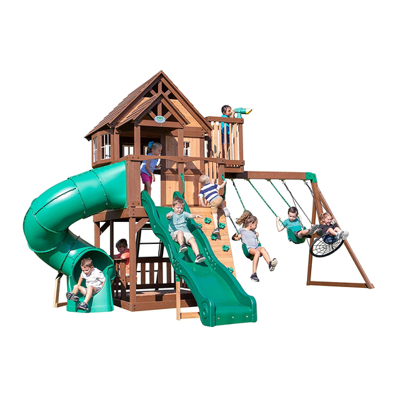
Backyard Discovery SKYFORT WITH TUBE SLIDE Owner's Manual & Assembly Instructions
Wooden swing set
Hide thumbs
Also See for SKYFORT WITH TUBE SLIDE:
- Owner's manual & assembly instructions (125 pages)
Table of Contents
Advertisement
Quick Links
SKYFORT
TUBE SLIDE
SAVE THIS ASSEMBLY MANUAL FOR FUTURE REFERENCE IN THE EVENT THAT
Made in China INS-2001015-A-SKYFORT WITH TUBE SLIDE-ENG-10-11-19
WITH
Model # 2001015
average 2 person assembly time
average tube slide assembly time
assembly time may vary based on skill level
For the most up to date assembly manual,
to register your set, or to order replacement parts please visit
www.backyarddiscovery.com
YOU NEED TO ORDER REPLACEMENT PARTS.
WOODEN SWING SET
Owner's Manual & Assembly Instructions
MANUFACTURED BY:
Backyard Discovery
3305 Airport Drive
Pittsburg, KS 66762
800-856-4445
Advertisement
Table of Contents

Related Manuals for Backyard Discovery SKYFORT WITH TUBE SLIDE


Summary of Contents for Backyard Discovery SKYFORT WITH TUBE SLIDE
- Page 1 For the most up to date assembly manual, to register your set, or to order replacement parts please visit www.backyarddiscovery.com SAVE THIS ASSEMBLY MANUAL FOR FUTURE REFERENCE IN THE EVENT THAT YOU NEED TO ORDER REPLACEMENT PARTS. Made in China INS-2001015-A-SKYFORT WITH TUBE SLIDE-ENG-10-11-19...
- Page 2 INSTALLATION SERVICES AVAILABLE! Need a helping hand? Let our team of professionals handle the installation for you! *Installation services are only available to U.S. customers. With Go Configure, we bring you 18 years of experience right to your doorstep. We service a wide array of indoor and outdoor recreation products that most consumers don’t have the time or ability to deliver &...
- Page 3 Owner’s Manual Please Read This Before Starting Assembly MISSING A PART? CALL US BEFORE GOING BACK TO THE STORE Th e store where you made your purchase does not stock parts for this item. If you have assembly questions or you are missing or have damaged parts, please call 1-800-856-4445 you can also visit www.backyarddiscovery.com...
- Page 4 Botanical, Adventure Playsets, and Leisure Time Products. Backyard Discovery warrants that this product is free from defect in materials and workmanship for a period of one (1) year from the original date of purchase. Th is one (1) year warranty covers all parts including wood, hardware, and accessories. All wood carries a fi ve (5) year pro-rated warranty against rot and decay. Refer to the schedule below for charges associated with replacement of parts under this Limited Warranty.
- Page 5 Owner’s Manual Operating Instructions and Safety Warnings WARNING: BURN HAZARD • Pay special attention to plastic and metal surfaces as they may be hot enough to cause burns. • Always check the temperature of the product before NOTE: letting your children play on it. •...
- Page 6 Owner’s Manual Please Read This Before Starting Assembly Positioning Your Playcenter Suggested Playground Surfacing • Th e playcenter is designed to be installed on a level • Do not install home playground equipment over surface by an adult with an adult helper. Place concrete, asphalt, packed earth, grass, carpet, or any in a fl at area of your yard to minimize ground other hard surface.
- Page 7 Owner’s Manual Please Read This Before Starting Assembly APPENDIX A The following information is from the United States X3.1.3.2 Do not install loose-fi ll surfacing over hard surfaces such as concrete or asphalt. Consumer Product Safety Commission’s Information X3.1.4 Poured-In-Place Surfaces or Pre-Manufactured Sheet for playground surfacing material;...
- Page 8 Check all moving parts including swing seats, third party person or service to assemble this product. ropes, cables, and chains for wear, rust, or other Backyard Discovery assumes no responsibility or deterioration. Replace as needed. liability for any charge incurred by the Customer for any assembly services’...
- Page 9 About Our Wood Backyard Discovery uses 100% Cedar (C. Lanceolata) wood. Although we take great care in selecting the best quality lumber available, wood is still a product of nature and susceptible to weathering which can change the appearance of your set.
- Page 10 Owner’s Manual Assembly Tips Protrusion Hazard Incorrect Correct If you see exposed threads and your bolt protrudes beyond the T-Nut you may have over tightened the bolt or used incorrect hardware. If you’ve overtightened, remove the bolt and add washers to eliminate the protrusion.
- Page 11 Owner’s Manual Assembly Tips ASSEMBLY TIP: Keep an eye out for these boxes which will contain helpful pictures and information making the assembly process as quick and painless as possible. Sorting Wood When removing the wood from the boxes we recommend arranging them by part number before you begin assembly.
- Page 12 Owner's Manual Tools Required for Installation...
- Page 13 Owner's Manual Basic Setup Dimensions & Assembly Notes Place the set on level ground, not less than 6'-7" [2 m] from any structure or obstruction such as a fence, garage, house, overhanging branches, laundry lines, or electrical wires. • While assembling unit, take time before and after each phase to make sure fort is level. If fort is not level, assembly will be difficult and improper assembly may result.
- Page 14 Parts Identification Owner's Manual Wood Components (Not to Scale) SWING BEAM - W4L12789 3 3/8"x5 1/4"x89 1/2" (86x134x2274) SB 9" BLOCK - W4L12790 3 3/8"x5 1/4"x9" (86x134x228) TOWER LEG - W4L12680 3"x3"x89 1/2" (76x76x2274) TOWER LEG - W4L12681 3"x3"x89 1/2" (76x76x2274) TOWER LEG - W4L12682 3"x3"x59"...
- Page 15 Parts Identification Owner's Manual Wood Components (Not to Scale) END SUPPORT - W4L08131 1 3/8"x3 3/8"x44 1/8" (36x86x1120) LEFT UPRIGHT - W4L12693 1 3/8"x3 3/8"x64 3/8" (36x86x1634) RIGHT UPRIGHT - W4L12694 1 3/8"x3 3/8"x64 3/8" (36x86x1634) TELESCOPE MOUNTING BLOCK - W4L12695 1 3/8"x2 3/8"x3"...
- Page 16 Parts Identification Owner's Manual Wood Components (Not to Scale) BOTTOM FLOOR RAIL - W4L12704 1"x5 1/4"x80" (24x134x2032) GROUND BOARD - W4L08134 1"x5 1/4"x86 3/4" (24x134x2202) WALL RAIL - W4L12706 1"x3 3/8"x80" (24x86x2032) WALL RAIL - W4L12707 1"x3 3/8"x80" (24x86x2032) PICNIC TABLE RAIL - W4L12708 1"x3 3/8"x67 1/4"...
- Page 17 Parts Identification Owner's Manual Wood Components (Not to Scale) ROOF RAFTER - W4L12717 1"x3 3/8"x50 3/8" (24x86x1278) FORT WALL RAIL - W4L12718 1"x3 3/8"x50 1/4" (24x86x1277) SWING BEAM MOUNT - W4L12719 1"x3 3/8"x50 1/4" (24x86x1277) PICNIC TABLE SEAT - W4L12720 1"x3 3/8"x35 3/8"...
- Page 18 Parts Identification Owner's Manual Wood Components (Not to Scale) PICNIC TABLE SUPPORT - W4L12730 1"x3 3/8"x28 5/8" (24x86x728) FRONT WALL RAIL - W4L12731 1"x3 3/8"x60 1/2" (24x86x1537) CROWS NEST WALL RAIL - W4L12732 1"x3 3/8"x26 1/4" (24x86x666) CROWS NEST WALL RAIL - W4L12733 1"x3 3/8"x29 7/8"...
- Page 19 Parts Identification Owner's Manual Wood Components (Not to Scale) TOP WALL RAIL - W4L12743 5/8"x3 3/8"x80" (16x86x2032) BOTTOM WALL RAIL - W4L12744 5/8"x3 3/8"x80" (16x86x2032) BOTTOM WALL RAIL - W4L12745 5/8"x3 3/8"x60 1/2" (16x86x1537) CROWS NEST WALL RAIL - W4L12746 5/8"x3 3/8"x29 7/8"...
- Page 20 Parts Identification Owner's Manual Wood Components (Not to Scale) CENTER PICNIC TABLE TOP - W4L12757 5/8"x3"x38 1/4" (16x76x973) FRONT WINDOW WALL BOARD - W4L12758 5/8"x3 3/8"x35" (16x86x889) GABLE BOARD - W4L12759 5/8"x3 3/8"x32 3/8" (16x86x822) FRONT PORCH ROOF SUPPORT - W4L12760 5/8"x3 3/8"x30 5/8"...
- Page 21 Parts Identification Owner's Manual Wood Components (Not to Scale) FRONT WINDOW WALL BOARD - W4L12769 5/8"x3 3/8"x6 3/8" (16x86x162) WALL RAIL - W4L12770 5/8"x3 3/8"x6 3/8" (16x86x162) ATTACHMENT BOARD - W4L12771 5/8"x3 3/8"x22 7/8" (16x86x580) SLIDE BED SUPPORT - W100935 5/8"x3 3/8"x19 7/8"...
- Page 22 Parts Identification Owner's Manual Wood Components (Not to Scale) FRONT PORCH GABLE TRIM - W4L12782 5/8"x2 3/8"x9 1/2" (16x60x241) CROWS NEST WALL BOARD - W4L12783 5/8"x1 3/8"x32 1/2" (16x34x825) (16) SAFETY BOARD - W4L12784 5/8"x1 3/8"x28 5/8" (16x34x726) SLIDE ATTACHMENT BOARD - W4L12792 1"x4 1/4"x27"...
- Page 23 Parts Identification Owner's Manual Wood Components (Not to Scale) LEFT PORCH PEAK ROOF PANEL - W2A02650 1 5/8"x10 1/2"x32 7/8" (42x268x834) LEFT PORCH ROOF PANEL - W2A02651 1 5/8"x15 5/8"x32 7/8" (42x396x834) PEAK ROOF PANEL - W2A02652 1 5/8"x20 5/8"x59" (42x524x1499) RIGHT PORCH PEAK ROOF PANEL - W2A02653 1 5/8"x10 1/2"x32 7/8"...
- Page 24 Parts Identification Owner's Manual Hardware Components H100363 BOLT WH BLK 5/16X6 H100396 BOLT WH BLK H100415 BOLT WH BLK (14) 5/16x1/2 (34) 5/16x3 3/4 H100115 BOLT WH H100503 BOLT WH BLK (15) 5/16x1/2 5/16x3-1/2 H100222 BOLT WH H100484 BOLT WH BLK 5/16x3/4 5/16x3 1/4 H100468...
- Page 25 Parts Identification Owner's Manual Hardware Components A100041 TORX WRENCH T-40 A100042 TORX BIT H100147 TORX BIT T-40 T-30 H100114 TORX WRENCH T-30 H100654 BOLT HEX (13) 3/8x5-1/2 H100761 BOLT HEX BLK H100471 LAG SCREW WH BLK 5/16x2 5/16x1 1/2 H100764 SCREW SETTER H100657 BOLT HEX BLK...
- Page 26 Parts Identification Owner's Manual Hardware Components H100090 SCREW PFH (41) 8x2 1/2" H100107 WASHER LOCK INT H100030 WASHER LOCK EXT H100091 SCREW PFH (13) 10x18 8x19 8X2 1/4 H100111 SCREW PFH (13) H100108 WASHER LOCK INT (26) 8x15 H100089 SCREW PFH H100102 WASHER FLAT 8x1 3/4...
- Page 27 Parts Identification Owner's Manual Accessory Components (Not to Scale) A100027 SWING SEAT GREEN A100030 SLIDE RAIL 10' BOTTOM LEFT GREEN A100032 SLIDE RAIL 10' TOP LEFT GREEN A100031 SLIDE RAIL 10' BOTTOM RIGHT GREEN A100033 SLIDE RAIL 10' TOP RIGHT GREEN A6P00037 GREEN HC ROCK GREEN HC ROCK...
- Page 28 Parts Identification Owner's Manual Accessory Components (Not to Scale) A100047 CHAIN GREEN 57" A100134 HAND GRIP GREEN 816 C/C A100324 LADDER RUNG 578 GREEN HAND GRIP A100118 METAL GREEN A100069 381 c/c QUICK LINK (1) TUBE SLIDE ASSEMBLY A100314 "A" REVISION TAG SWING BEAM SWING BEAM A100325...
- Page 29 SLIDE ASSEMBLY STEP 1 SLIDE BED SUPPORT - W100935 5/8"x3 3/8"x19 7/8" (16x86x505) A6P00385 SLIDE BED 10' DARK GREEN (x1) H100115 BOLT WH H100074 T-NUT (x3) (x3) 5/16x1/2 5/16 (x1) SLIDE BED 10' DARK GREEN TIP: SEE SLIDE ASSEMBLY INSTALLATION STEP FOR DECK MOUNTING HOLE DRILLING LOCATIONS.
- Page 30 SLIDE ASSEMBLY STEP 2 60" SLIDE A4M01091 A100031 A100033 SLIDE RAIL 10' BOTTOM RIGHT GREEN BRACE (RIGHT) SLIDE RAIL 10' TOP RIGHT GREEN (x1) (x1) A100030 60" SLIDE A100032 A4M01092 SLIDE RAIL 10' BOTTOM LEFT GREEN SLIDE RAIL 10' TOP LEFT GREEN (x1) (x1) BRACE (LEFT)
- Page 31 SLIDE ASSEMBLY STEP 3 A100034 SLIDE SUPPORT TUBE (x4) NOTE: PLACE (1) SLIDE RAIL ASSEMBLY ON A FLAT SURFACE AND BEGIN INSERTING SLIDE BED AT THE BOTTOM OF THE SLIDE RAIL (FIG. 1). HAVE A HELPER BEND THE SLIDE BED TOWARDS THE TOP OF THE SLIDE AND INSERT THE BED INTO THE SLIDE CAVITY.
- Page 32 SLIDE ASSEMBLY STEP 4 H100090 SCREW PFH (x38) 8x2 1/2" NOTE: ONCE THE SLIDE BED, SUPPORT TUBES, AND SUPPORT BOARD ARE COMPLETELY IN THE CAVITY AND SUPPORT POCKET, SECURE USING 2-1/2" SCREWS AT EACH OF THE PILOT HOLE LOCATIONS AS SHOWN. REPEAT PROCESS FOR OPPOSITE SLIDE RAIL.
- Page 33 SLIDE ASSEMBLY STEP 5 SLIDE BRACE WIDE - W4L13300 NUT BARREL WH H100031 WASHER LOCK H100115 BOLT WH H100005 1"x3 3/8"x18 3/4" (24x86x476) (x8) 5/16x7/8 5/16x1/2 12x19 H100111 SCREW PFH (x4) SLIDE BRACE UPRIGHT - W4L13301 1"x3 3/8"x22 7/8" (24x86x580) 005 (x8) NUT BARREL - 7/8"...
- Page 34 LADDER ASSEMBLY STEP 1 LEFT UPRIGHT - W4L12693 1 3/8"x3 3/8"x64 3/8" (36x86x1634) H100391 SCREW PFH BLK (10) LADDER RUNG - W4L12736 1"x3 3/8"x18 1/8" (24x86x460) (x1) (x5) (x10) SCREW - 2"...
- Page 35 STEP 2 LADDER ASSEMBLY H100391 SCREW PFH BLK RIGHT UPRIGHT - W4L12694 (10) 1 3/8"x3 3/8"x64 3/8" (36x86x1634) (x1) (x10) SCREW - 2"...
- Page 36 STEP 3 LADDER ASSEMBLY ATTACHMENT BOARD - W4L12737 1"x3 3/8"x20 1/8" (24x86x512) H100391 SCREW PFH BLK REAR SUPPORT - W4L12772 5/8"x3 3/8"x20 1/8" (16x86x512) (x8) (x1) SCREW - 2" (x1)
- Page 37 STEP 4 LADDER ASSEMBLY H100503 BOLT WH BLK 5/16x3-1/2 A100134 HAND GRIP GREEN 816 C/C H100379 T-NUT BLK 5/16 (x4) T-NUT - 5/16" (x4) BOLT - 3 1/2" (x2) HAND GRIP GREEN 816 C/C...
- Page 38 ROCKWALL STEP 1 ASSEMBLY ROCK WALL BOARD - W4L12774 H100108 WASHER LOCK 5/8"x3 3/8"x22 7/8" (16x86x580) (24) A6P00036 GREEN HC ROCK #1 8x15 H100063 BOLT PTH H100072 ROCK WALL BOARD - W4L12775 T-NUT A6P00037 GREEN HC ROCK #2 (24) 1/4x3/4 (24) 5/8"x3 3/8"x22 7/8"...
- Page 39 ROCKWALL STEP 2 ASSEMBLY LEFT ROCK ASSEMBLY ROCK WALL BOARD - W4L12773 5/8"x3 3/8"x22 7/8" (16x86x580) (10) H100086 SCREW PFH DOUBLE ROCK ASSEMBLY (72) 8x1 1/2 RIGHT ROCK ASSEMBLY ROCKWALL RAIL - W4L12735 1"x3 3/8"x61 3/4" (24x86x1570) (x72) SCREW - 1 1/2" RECOMMENDED BOARD 1/8 in PLACEMENT PATTERN...
- Page 40 ROCKWALL STEP 3 ASSEMBLY H100200 SCREW PFH BLK 8x1 1/2 ROCK WALL END BOARD - W4L12787 5/8"x4"x22 7/8" (16x102x580) (x4) SCREW - 1 1/2" (x1) SIDE VIEW 5/8 in...
- Page 41 ROCKWALL STEP 4 ASSEMBLY 1 1/2 in H100200 SCREW PFH BLK 8x1 1/2 ATTACHMENT BOARD - W4L12771 5/8"x3 3/8"x22 7/8" (16x86x580) H100379 T-NUT BLK 5/16 (x1) (x2) T-NUT - 5/16" (x4) SCREW - 1 1/2" (x1) SIDE VIEW T-NUTS TO THE INSIDE WHEN INSTALLING BOARD...
- Page 42 STEP 1 BAY WINDOW H100200 SCREW PFH BLK (40) 8x1 1/2 BAY WINDOW HEADER - W4L12702 1"x5 1/4"x45 1/4" (24x134x1150) H100385 SCREW PFH BLK BAY WINDOW PANEL - W2A02656 7/8"x15 3/4"x20 3/4" (21x400x526) REPEAT STEP TO COMPLETE (2) BAY WINDOW ASSEMBLIES. (x8) SCREW - 1 1/2"...
- Page 43 STEP 1 PORCH ROOF H100483 SCREW PFH BLK 8x2 1/4 PORCH ROOF RAFTER - W4L12725 1"x3 3/8"x24 1/2" (24x86x622) 1/2 in 1 1/4 in USING A 3/16" DRILL BIT, MARK AND DRILL A PILOT HOLE INTO 'H20' RAFTER TO PREVENT SPLITTING. ONLY DRILL THROUGH ONE RAFTER NOT BOTH.
- Page 44 STEP 2 PORCH ROOF FRONT PORCH GABLE TRIM - W4L12782 FRONT PORCH ROOF SUPPORT - W4L12760 H100380 SCREW PFH BLK 5/8"x2 3/8"x9 1/2" (16x60x241) 5/8"x3 3/8"x30 5/8" (16x86x779) 8x1 1/8 FRONT PORCH GABLE TRIM - W4L12780 H100202 SCREW PWH BLK 5/8"x2 3/8"x15"...
- Page 45 STEP 3 PORCH ROOF H100391 SCREW PFH BLK LEFT PORCH PEAK ROOF PANEL - W2A02650 RIGHT PORCH PEAK ROOF PANEL - W2A02653 1 5/8"x10 1/2"x32 7/8" (42x268x834) 1 5/8"x10 1/2"x32 7/8" (42x268x834) (x1) FRONT ASSEMBLY BACK SIDE (x1) (x8) SCREW - 2"...
- Page 46 STEP 4 PORCH ROOF H100391 SCREW PFH BLK LEFT PORCH ROOF PANEL - W2A02651 RIGHT PORCH ROOF PANEL - W2A02654 1 5/8"x15 5/8"x32 7/8" (42x396x834) 1 5/8"x15 5/8"x32 7/8" (42x396x834) (x1) FRONT ASSEMBLY BACK SIDE (x1) (x8) SCREW - 2"...
- Page 47 STEP 1 SWING BEAM H100416 BOLT WH BLK SB 9" BLOCK - W4L12790 SWING BEAM - W4L12789 (10) 3 3/8"x5 1/4"x89 1/2" (86x134x2274) 5/16x3 3 3/8"x5 1/4"x9" (86x134x228) H100192 NUT BARREL WH BLK (10) 5/16x7/8 SWING BEAM SWING BEAM EXTENDED A100325 A4M00993 A100326...
- Page 48 STEP 2 SWING BEAM H100654 H100107 H100102 H100073 BOLT HEX WASHER LOCK INT WASHER FLAT T-NUT A4M00505 (12) (12) (12) (12) 3/8x5-1/2 10x18 11x25 SWING HANGER (x12) T-NUT - 3/8" (x6) SWING HANGER (x12) BOLT - 5-1/2" (x12) WASHER - 10x18" (x12) WASHER - 11x25"...
- Page 49 STEP 3 SWING BEAM H100363 BOLT WH BLK GROUND BOARD - W4L08134 5/16X6 1"x5 1/4"x86 3/4" (24x134x2202) H100415 BOLT WH BLK ANGLE BRACE - W4L13302 5/16x3 3/4 H100192 NUT BARREL WH BLK 1 3/8"x3 3/8"x87 1/8" (36x86x2212) 5/16x7/8 SWING BEAM SUPPORT - W4L12791 3 3/8"x3 3/8"x48 3/8"...
- Page 50 STEP 4 SWING BEAM H100416 BOLT WH BLK 5/16x3 (1) BEAM ASSEMBLY H100192 NUT BARREL WH BLK (1) END ASSEMBLY 5/16x7/8 TIGHTEN ALL BRACKET (x2) HARDWARE AT THIS TIME. NUT BARREL - 7/8" (x2) BOLT - 3"...
- Page 51 STEP 1 CROWS NEST H100201 SCREW PFH BLK 8x2-1/2 CROWS NEST FLOOR RAIL - W4L12690 CROWS NEST FLOOR RAIL - W4L12724 1 3/8"x3 3/8"x33 1/2" (36x86x852) 1"x3 3/8"x27" (24x86x686) H100379 T-NUT BLK 5/16 (x4) SCREW - 2 1/2" (x1) (x2) (x4) T-NUT - 5/16"...
- Page 52 STEP 2 CROWS NEST H100205 BOLT WH BLK H100379 T-NUT BLK 5/16x2-1/4 5/16 CROWS NEST DECK BRACE - W4L12691 1 7/16"x3 3/8"x10 7/8" (36x86x276) H100198 WASHER LOCK EXT BLK 8x19 (x2) (x2) T-NUT - 5/16" (x2) WASHER - 8x19 (x2) BOLT - 2 1/4"...
- Page 53 STEP 3 CROWS NEST H100086 SCREW PFH CROWS NEST FLOOR BOARD - W4L12742 CROWS NEST FLOOR BOARD - W4L13304 (30) 8x1 1/2 5/8"x4 3/8"x27" (16x112x686) 5/8"x4 3/8"x27" (16x112x686) (x30) SCREW - 1 1/2" (x1) (x6) NOTE HOLE LOCATIONS L2 BOARDS ONLY (x1) FLUSH 7/8 in...
- Page 54 STEP 4 CROWS NEST CROWS NEST FLOOR SUPPORT - W4L12726 H100087 SCREW PFH 1"x3 3/8"x24 1/8" (24x86x614) 8x1 1/4 (x2) SCREW - 1-1/4" MARK LOCATIONS SHOWN. USING AN 1/8" DRILL BIT 11 3/4 in DRILL 2 PILOT HOLES. (x1) 7 1/2 in 12 7/8 in 15 1/2 in...
- Page 55 STEP 1 FORT ASSEMBLY BOTTOM FLOOR RAIL - W4L12704 TOWER LEG - W4L12680 1"x5 1/4"x80" (24x134x2032) 3"x3"x89 1/2" (76x76x2274) TOWER LEG - W4L12688 TOP FLOOR RAIL - W4L12698 1 3/8"x3 3/8"x59" (36x86x1500) A4M00520 VERTICAL ID 1"x5 1/4"x80" (24x134x2032) PLATE TOWER LEG - W4L12682 3"x3"x59"...
- Page 56 STEP 2 FORT ASSEMBLY TOWER LEG - W4L12681 3"x3"x89 1/2" (76x76x2274) BOTTOM FLOOR RAIL - W4L12704 1"x5 1/4"x80" (24x134x2032) TOWER LEG - W4L12689 1 3/8"x3 3/8"x59" (36x86x1500) TOP FLOOR RAIL - W4L12699 1"x5 1/4"x80" (24x134x2032) TOWER LEG - W4L12683 3"x3"x59" (76x76x1500) H100415 BOLT WH BLK H100205...
- Page 57 STEP 3 FORT ASSEMBLY FRONT WALL RAIL - W4L12731 FLOOR RAIL - W4L12703 1"x3 3/8"x60 1/2" (24x86x1537) 1"x5 1/4"x60 1/2" (24x134x1537) FLOOR RAIL - W4L12700 1"x5 1/4"x60 1/2" (24x134x1537) H100458 LAG SCREW WH BLK H100197 LAG SCREW WH BLK 5/16x2 5/16x2 1/2 H100198 WASHER LOCK...
- Page 58 STEP 4 FORT ASSEMBLY H100197 LAG SCREW WH BLK FLOOR RAIL - W4L12701 5/16x2 1/2 1"x5 1/4"x60 1/2" (24x134x1537) H100198 WASHER LOCK EXT BLK 8x19 H100458 LAG SCREW WH BLK FLOOR RAIL - W4L12738 5/16x2 5/8"x5 1/4"x60 1/2" (16x134x1537) (x4) WASHER - 8x19 (x4) LAG SCREW - 2 1/2"...
- Page 59 STEP 5 FORT ASSEMBLY FLOOR RAIL - W4L12739 H100458 LAG SCREW WH BLK 5/8"x5 1/4"x60 1/2" (16x134x1537) 5/16x2 H100198 WASHER LOCK EXT BLK 8x19 FLOOR JOIST - W4L12729 H100201 SCREW PFH BLK 1"x3 3/8"x60 1/2" (24x86x1537) 8x2-1/2 (x1) FLUSH NOTE HOLE LOCATIONS (x4) SCREW - 2 1/2"...
- Page 60 STEP 6 FORT ASSEMBLY 2 5/8 in 1 3/4 in H100198 WASHER LOCK H100407 BOLT WH BLK EXT BLK 5/16x1 1/2 8x19 PICNIC TABLE SUPPORT - W4L12730 1"x3 3/8"x28 5/8" (24x86x728) H100379 T-NUT BLK 5/16 1 3/4 in END AT TOP (x1) (x1) BOLT - 1 1/2"...
- Page 61 STEP 7 FORT ASSEMBLY H100086 SCREW PFH (22) 8x1 1/2 BOTTOM FLOOR BOARD - W4L12786 5/8"x4"x35 1/4" (16x102x895) BOTTOM FLOOR PANEL - W2A02648 H100200 SCREW PFH BLK (16) 1 5/8"x13 1/2"x35 3/8" (40x344x897) 8x1 1/2 (x1) (x4) (x22) SCREW - 1 1/2" (x1) SPACE BOARDS &...
- Page 62 STEP 8 FORT ASSEMBLY BOTTOM WALL RAIL - W4L12745 H100197 LAG SCREW WH BLK 5/8"x3 3/8"x60 1/2" (16x86x1537) 5/16x2 1/2 H100198 WASHER LOCK EXT BLK 8x19 PICNIC TABLE RAIL - W4L12708 H100458 LAG SCREW WH BLK 1"x3 3/8"x67 1/4" (24x86x1708) 5/16x2 NOTE ANGLE CUT FACES DOWNWARD...
- Page 63 STEP 9 FORT ASSEMBLY BOTTOM WALL BOARD - W4L12766 5/8"x3 3/8"x21 3/8" (16x86x544) H100088 SCREW PFH (32) 8x1 1/8 3 1/16 in EQUAL SPACING NOTE: SPACING NOT LESS THAN 3 1/16 in, & NO MORE THAN 3 1/4 in. (x32) SCREW - 1 1/8"...
- Page 64 STEP 1 0 FORT ASSEMBLY H100458 LAG SCREW WH BLK 5/16x2 H100198 WASHER LOCK BOTTOM WALL RAIL - W4L12744 EXT BLK 5/8"x3 3/8"x80" (16x86x2032) 8x19 H100471 LAG SCREW WH BLK 5/16x1 1/2 (x2) (x2) LAG SCREW - 1 1/2" (x4) LAG SCREW - 2"...
- Page 65 STEP 1 1 FORT ASSEMBLY BOTTOM WALL BOARD - W4L12766 H100088 SCREW PFH (10) 5/8"x3 3/8"x21 3/8" (16x86x544) (40) 8x1 1/8 3 1/8 in 3 1/8 in EQUAL EQUAL SPACING SPACING (x40) (x10) SCREW - 1 1/8"...
- Page 66 STEP 1 2 FORT ASSEMBLY H100407 BOLT WH BLK H100197 LAG SCREW WH BLK 5/16x1 1/2 5/16x2 1/2 PICNIC TABLE SEAT RAIL - W4L12721 1"x3 3/8"x17 1/2" (24x86x444) H100198 WASHER LOCK EXT BLK H100379 T-NUT BLK 8x19 5/16 (x1) BOLT - 1 1/2" USING 'H16' AS A GUIDE, DRILL 3/8"...
- Page 67 STEP 13 FORT ASSEMBLY H100197 LAG SCREW WH BLK H100378 BOLT WH BLK 5/16x2 1/2 5/16x1 3/4 PICNIC TABLE SEAT RAIL - W4L12722 1"x3 3/8"x17 1/2" (24x86x444) H100198 WASHER LOCK EXT BLK H100379 T-NUT BLK 8x19 5/16 (x1) (x1) BOLT - 1 3/4" (x1) T-NUT - 5/16"...
- Page 68 STEP 14 FORT ASSEMBLY PICNIC TABLE SEAT - W4L12720 H100111 SCREW PFH 1"x3 3/8"x35 3/8" (24x86x897) (x8) SCREW - 2" (x2)
- Page 69 STEP 15 FORT ASSEMBLY H100378 BOLT WH BLK H100197 LAG SCREW WH BLK 5/16x1 3/4 5/16x2 1/2 PICNIC TABLE TOP SUPPORT - W4L12727 1"x3 3/8"x16 1/2" (24x86x418) H100198 WASHER LOCK EXT BLK H100379 T-NUT BLK 8x19 5/16 (x1) (x1) WASHER - 8x19 T-NUT - 5/16"...
- Page 70 STEP 16 FORT ASSEMBLY H100086 SCREW PFH PICNIC TABLE TOP - W4L12755 CENTER PICNIC TABLE TOP - W4L12757 (20) 8x1 1/2 5/8"x3 3/8"x41 1/4" (16x86x1049) 5/8"x3"x38 1/4" (16x76x973) H100088 SCREW PFH PICNIC TABLE TOP - W4L12793 8x1 1/8 PICNIC TABLE TOP CLEAT - W4L12767 5/8"x3 3/8"x41 1/4"...
- Page 71 STEP 17 FORT ASSEMBLY H100391 SCREW PFH BLK TOP FLOOR SUPPORT - W4L12728 1"x3 3/8"x3" (24x86x76) FLUSH (x2) REPEAT ON OPPOSITE END (x4) SCREW - 2"...
- Page 72 STEP 18 FORT ASSEMBLY 12 5/8 in H100088 SAFETY BOARD - W4L12784 SCREW PFH 5/8"x1 3/8"x28 5/8" (16x34x726) 8x1 1/8 (x3) SCREW - 1 1/8" NOTE HOLE LOCATIONS (x1) CENTER IN OPENING...
- Page 73 STEP 19 FORT ASSEMBLY H100205 BOLT WH BLK H100197 LAG SCREW WH BLK 5/16x2-1/4 5/16x2 1/2 DECK BRACE - W4L12692 1 7/16"x3 3/8"x20" (36x86x508) H100198 WASHER LOCK H100379 (16) EXT BLK T-NUT BLK 5/16 8x19 (x8) (x8) WASHER - 8x19 (x8) T-NUT - 5/16"...
- Page 74 STEP 20 FORT ASSEMBLY H100458 LAG SCREW WH BLK FLOOR RAIL - W4L12710 5/16x2 1"x3 3/8"x60 1/2" (24x86x1537) H100198 WASHER LOCK EXT BLK 8x19 FLOOR JOIST - W4L12729 1"x3 3/8"x60 1/2" (24x86x1537) H100201 SCREW PFH BLK 8x2-1/2 NOTE: FLUSH TOPS OF BOARDS. ALL PLACES.
- Page 75 STEP 21 FORT ASSEMBLY H100086 SCREW PFH FLOOR PANEL - W2A02649 (94) H100379 8x1 1/2 T-NUT BLK 1 1/4"x13 1/2"x81 7/8" (32x344x2080) 5/16 TOP FLOOR BOARD - W4L12785 5/8"x4"x78" (16x102x1980) T-NUT - 5/16" SEE BELOW TIP: INSTALL T-NUTS ON BOTTOM SIDE OF BOTH Y1 BOARDS BEFORE ATTACHING TO FORT.
- Page 76 STEP 22 FORT ASSEMBLY 1 3/4 in 1 1/2 in FORT WALL RAIL - W4L12761 ROOF SUPPORT RAIL - W4L12709 BACK RIGHT FORT CORNER - W4L12687 3"x3"x53 7/8" (76x76x1370) 5/8"x3 3/8"x30 1/4" (16x86x768) 1"x3 3/8"x67 1/4" (24x86x1709) BACK LEFT FORT CORNER - W4L12684 BACK FORT RAIL - W4L12711 L BRACKET A100340...
- Page 77 STEP 23 FORT ASSEMBLY H100458 LAG SCREW WH BLK TOP WALL RAIL - W4L12743 5/16x2 5/8"x3 3/8"x80" (16x86x2032) 1 1/2 1 3/4 FORT WALL RAIL - W4L12752 H100198 WASHER LOCK EXT BLK 1"x3 3/8"x50 1/4" (24x86x1277) 8x19 WALL RAIL - W4L12770 5/8"x3 3/8"x6 3/8"...
- Page 78 STEP 24 FORT ASSEMBLY H100379 T-NUT BLK H100198 FORT WALL RAIL - W4L12723 WASHER LOCK 5/16 EXT BLK 1"x3 3/8"x29 7/8" (24x86x758) L BRACKET A100340 8x19 2.5x38x50x55 H100199 WASHER LOCK H100378 BOLT WH BLK H100396 BOLT WH BLK H100192 NUT BARREL WH H100459 BOLT WH BLK EXT BLK...
- Page 79 STEP 25 FORT ASSEMBLY WALL RAIL - W4L12706 1"x3 3/8"x80" (24x86x2032) SLIDE ATTACHMENT BOARD - W4L12792 1"x4 1/4"x27" (24x108x687) FRONT LEFT FORT CORNER - W4L12685 A100340 L BRACKET SLIDE ATTACHMENT BOARD - W4L12781 3"x3"x53 7/8" (76x76x1370) 2.5x38x50x55 1"x3"x23" (24x76x585) H100503 BOLT WH BLK H100396 BOLT WH BLK...
- Page 80 STEP 26 FORT ASSEMBLY WALL RAIL - W4L12707 1"x3 3/8"x80" (24x86x2032) 1 1/2 L BRACKET A100340 2.5x38x50x55 FRONT RIGHT FORT CORNER - W4L12686 3"x3"x53 7/8" (76x76x1370) H100415 BOLT WH BLK H100396 BOLT WH BLK H100484 BOLT WH BLK H100192 NUT BARREL WH BLK 5/16x3 3/4 5/16x1/2 5/16x3 1/4...
- Page 81 STEP 27 FORT ASSEMBLY FORT WALL BOARD - W4L12714 1"x3 3/8"x50 1/2" (24x86x1284) A100396 L BRACKET 51x32x82x3.175 H100477 WASHER SPLIT H100761 BOLT HEX BLK H100379 T-NUT BLK H100198 WASHER LOCK H100407 BOLT WH BLK 5/16x2 5/16 H100478 WASHER FLAT EXT BLK 5/16x1 1/2 5/16 8x19...
- Page 82 STEP 28 FORT ASSEMBLY H100407 BOLT WH BLK H100089 H100415 BOLT WH BLK SCREW PFH FORT WALL RAIL - W4L12740 5/16x1 1/2 8x1 3/4 5/16x3 3/4 5/8"x5 1/4"x50 1/4" (16x134x1277) H100458 LAG SCREW WH BLK SWING BEAM MOUNT - W4L12719 H100379 T-NUT BLK H100198...
- Page 83 STEP 29 FORT ASSEMBLY H100378 BOLT WH BLK 5/16x1 3/4 H100379 T-NUT BLK 5/16 (1) LADDER ASSEMBLY H100198 WASHER LOCK EXT BLK 8x19 (x2) T-NUT - 5/16" (x2) WASHER - 8x19 (x2) BOLT - 1 3/4" LADDER ASSEMBLY (x1)
- Page 84 STEP 30 FORT ASSEMBLY ROOF SUPPORT RAIL - W4L12709 H100415 BOLT WH BLK 1"x3 3/8"x67 1/4" (24x86x1709) 5/16x3 3/4 FRONT FORT WALL RAIL - W4L12712 H100198 WASHER LOCK 1"x3 3/8"x60 1/2" (24x86x1537) EXT BLK H100379 T-NUT BLK 8x19 5/16 (x4) BOLT - 3 3/4"...
- Page 85 STEP 31 FORT ASSEMBLY 1 3/4 in 1 1/2 in A100340 L BRACKET FORT UPRIGHT - W4L12713 FORT WALL RAIL - W4L12761 2.5x38x50x55 1"x3 3/8"x50 1/2" (24x86x1284) 5/8"x3 3/8"x30 1/4" (16x86x768) H100458 LAG SCREW WH BLK H100407 BOLT WH BLK H100459 BOLT WH BLK H100396...
- Page 86 STEP 32 FORT ASSEMBLY H100458 LAG SCREW WH BLK 5/16x2 FORT WALL RAIL - W4L12718 1"x3 3/8"x50 1/4" (24x86x1277) H100198 WASHER LOCK EXT BLK 8x19 (x1) (x2) WASHER - 8x19 (x2) LAG SCREW - 2"...
- Page 87 STEP 33 FORT ASSEMBLY NOTE: NOTE: PORCH LEG - W4L12715 HOLES GO OUTWARD HOLES GO OUTWARD 1"x3 3/8"x50 1/2" (24x86x1282) WHEN INSTALLED. WHEN INSTALLED. H100199 WASHER LOCK EXT BLK 12x19 A100340 L BRACKET PORCH LEG - W4L12716 1"x3 3/8"x50 1/2" (24x86x1282) 2.5x38x50x55 H100198 WASHER LOCK...
- Page 88 STEP 34 FORT ASSEMBLY FORT WALL BOARD - W4L12776 FORT WALL BOARD - W4L12750 5/8"x2 3/8"x50 1/2" (16x60x1284) 5/8"x3 3/8"x50 1/2" (16x86x1284) FORT WALL BOARD - W4L12751 FORT WALL BOARD - W4L12762 FORT WALL BOARD - W4L12763 5/8"x3"x50 1/2" (16x76x1284) 5/8"x3 1/8"x29 7/8"...
- Page 89 STEP 35 FORT ASSEMBLY FORT WALL BOARD - W4L12748 WALL BOARD - W4L12765 WALL BOARD - W4L12764 5/8"x3 3/8"x53 7/8" (16x86x1370) 5/8"x3 3/8"x26 1/8" (16x86x664) 5/8"x3 3/8"x29 7/8" (16x86x758) H100088 SCREW PFH (38) 8x1 1/8 (x2) (x38) SCREW - 1 1/8" (x1) (x6)
- Page 90 STEP 36 FORT ASSEMBLY FORT WALL BOARD - W4L12750 FRONT WINDOW WALL BOARD - W4L12758 5/8"x3 3/8"x50 1/2" (16x86x1284) 5/8"x3 3/8"x35" (16x86x889) H100088 SCREW PFH (35) 8x1 1/8 FRONT WINDOW WALL BOARD - W4L12769 5/8"x3 3/8"x6 3/8" (16x86x162) (x2) (x2) (x35) SCREW - 1 1/8"...
- Page 91 STEP 37 FORT ASSEMBLY WALL BOARD - W4L12764 H100088 (13) 5/8"x3 3/8"x29 7/8" (16x86x758) SCREW PFH (52) 8x1 1/8 (x52) SCREW - 1 1/8" (x13)
- Page 92 STEP 38 FORT ASSEMBLY WALL BOARD - W4L12764 H100088 SCREW PFH 5/8"x3 3/8"x29 7/8" (16x86x758) (16) 8x1 1/8 2 5/8 in EQUAL SPACING (x16) SCREW - 1 1/8" (x4)
- Page 93 STEP 39 FORT ASSEMBLY H100391 SCREW PFH BLK (20) H100128 SCREW PWH (24) 8x5/8 (2) BAY WINDOW ASSEMBLY (x24) SCREW - 5/8 (x20) BAY WINDOW ASSEMBLY SCREW - 2" BAY WINDOW ASSEMBLY...
- Page 94 STEP 40 FORT ASSEMBLY H100070 SCREW PWH 8x3/4 A100014 PLASTIC WINDOW WHITE (x1) (x4) PLASTIC WINDOW WHITE SCREW - 8x3/4"...
- Page 95 STEP 41 FORT ASSEMBLY A100324 H100468 BOLT WH BLK LADDER RUNG 578 GREEN 5/16x1 H100379 T-NUT BLK 5/16 (x4) T-NUT - 5/16" (x2) LADDER RUNG 578 GREEN (x4) BOLT WH - 1"...
- Page 96 STEP 42 FORT ASSEMBLY H100379 T-NUT BLK H100378 BOLT WH BLK 5/16 5/16x1 3/4 ROOF RAFTER - W4L12717 1"x3 3/8"x50 3/8" (24x86x1278) H100483 SCREW PFH BLK H100198 WASHER LOCK 8x2 1/4 EXT BLK 8x19 1 in USING A 3/16" DRILL BIT, MARK AND DRILL A PILOT HOLE INTO 'H12' RAFTER TO PREVENT SPLITTING.
- Page 97 STEP 43 FORT ASSEMBLY GABLE BOARD - W4L12747 5/8"x3 3/8"x59 1/2" (16x86x1510) H100088 SCREW PFH 8x1 1/8 GABLE BOARD - W4L12749 5/8"x3 3/8"x52 5/8" (16x86x1338) (x8) SCREW - 1 1/8" (x1) (x1) (x1) (x1)
- Page 98 STEP 44 FORT ASSEMBLY GABLE BOARD - W4L12754 GABLE BOARD - W4L12759 5/8"x3 3/8"x45 7/8" (16x86x1166) 5/8"x3 3/8"x32 3/8" (16x86x822) H100088 SCREW PFH 8x1 1/8 GABLE BOARD - W4L12756 5/8"x3 3/8"x39 1/8" (16x86x994) (x1) (x1) (x1) (x6) SCREW - 1 1/8"...
- Page 99 STEP 45 FORT ASSEMBLY GABLE BOARD - W4L12754 GABLE BOARD - W4L12759 5/8"x3 3/8"x45 7/8" (16x86x1166) 5/8"x3 3/8"x32 3/8" (16x86x822) H100088 SCREW PFH 8x1 1/8 GABLE BOARD - W4L12756 5/8"x3 3/8"x39 1/8" (16x86x994) (x6) SCREW - 1 1/8" (x1) (x1) (x1)
- Page 100 STEP 46 FORT ASSEMBLY FRONT PORCH GABLE TRIM - W4L12780 5/8"x2 3/8"x15" (16x60x381) H100380 SCREW PFH BLK (18) 8x1 1/8 TRIANGLE SUNBURST - W4L12741 5/8"x5 1/4"x10 3/8" (16x134x265) FRONT PORCH GABLE TRIM - W4L12782 H100088 SCREW PFH 5/8"x2 3/8"x9 1/2" (16x60x241) 8x1 1/8 1 1/8 in REPEAT ON BOTH ENDS...
- Page 101 STEP 47 FORT ASSEMBLY SOFFIT CAP - W4L12753 5/8"x3 3/8"x50 1/4" (16x86x1277) H100200 SCREW PFH BLK 8x1 1/2 SOFFIT CAP - W4L12777 5/8"x2 3/8"x50 1/4" (16x60x1277) (x6) SCREW - 1 1/2" (x1) (x1)
- Page 102 STEP 48 FORT ASSEMBLY H100483 SCREW PFH BLK (14) 8x2 1/4 ROOF PANEL - W2A02655 PEAK ROOF PANEL - W2A02652 1 5/8"x15 5/8"x59" (42x396x1499) 1 5/8"x20 5/8"x59" (42x524x1499) NOTE: START WITH TOP PANEL FIRST. FLUSH EDGES. (x14) SCREW - 8x2 1/4" (x1) (x2)
- Page 103 STEP 49 FORT ASSEMBLY ROOF SUPPORT - W4L12778 H100380 SCREW PFH BLK 5/8"x2 3/8"x47" (16x60x1193) 8x1 1/8 25 7/8 1 in 2 1/2 (x9) SCREW - 1 1/8" (x1)
- Page 104 STEP 50 FORT ASSEMBLY REPEAT STEPS 48 & 49 TO ATTACH LEFT SIDE ROOF PANELS.
- Page 105 STEP 51 FORT ASSEMBLY H100195 BOLT WH BLK H100194 BOLT WH BLK H100378 BOLT WH BLK 5/16x2-3/4 5/16x2 1/2 5/16x1 3/4 H100198 WASHER LOCK H100379 T-NUT BLK EXT BLK (1) PORCH ROOF ASSEMBLY 5/16 8x19 PORCH ROOF ASSEMBLY (x2) T-NUT - 5/16" (x2) WASHER - 8x19 (x2)
- Page 106 STEP 52 FORT ASSEMBLY H100657 BOLT HEX BLK 5/16x1 3/4 H100478 WASHER FLAT 8x27 H100477 WASHER SPLIT H100379 T-NUT BLK (1) SWING BEAM ASSEMBLY 5/16 5/16 (x4) (x4) WASHER - 8x27 WASHER - 5/16 (x4) (x4) BOLT - 5/16x1 3/4 T-NUT - 5/16"...
-
Page 107: Table Of Contents
STEP 53 FORT ASSEMBLY H100481 BOLT HEX BLK 5/16x1 1/4 H100197 LAG SCREW WH H100192 NUT BARREL WH H100086 SCREW PFH 5/16x2 1/2 5/16x7/8 8x1 1/2 H100198 WASHER LOCK EXT BLK (1) CROWS NEST DECK ASSEMBLY 8x19 H100477 WASHER SPLIT H100199 WASHER LOCK H100478... -
Page 108: Washer - 8X27
STEP 54 FORT ASSEMBLY H100477 WASHER SPLIT H100659 LAG SCREW BLK H100478 WASHER FLAT 5/16x1 1/2 A100396 L BRACKET 51x32x82x3.175 5/16 8x27 USING BRACKET AS A GUIDE. DRILL 3/16" DIA PILOT HOLES 1" IN DEPTH. (2 PLCS EACH SIDE). (x4) WASHER - 8x27 (x2) (x4) - Page 109 STEP 55 FORT ASSEMBLY H100195 BOLT WH BLK CROWS NEST WALL SUPPORT - W4L12697 5/16x2-3/4 1 3/8"x2 3/8"x37 1/2" (36x60x952) H100198 WASHER LOCK CROWS NEST WALL SUPPORT - W4L12696 H100379 T-NUT BLK EXT BLK 1 3/8"x2 3/8"x37 1/2" (36x60x952) 5/16 8x19 (x2) NOTE HOLE...
-
Page 110: Lag Screw Wh Blk
STEP 56 FORT ASSEMBLY CROWS NEST WALL RAIL - W4L12734 H100197 LAG SCREW WH BLK H100205 BOLT WH BLK 1"x3 3/8"x34 1/2" (24x86x876) 5/16x2 1/2 5/16x2-1/4 H100198 WASHER LOCK H100379 T-NUT BLK CROWS NEST WALL RAIL - W4L12733 EXT BLK 1"x3 3/8"x29 7/8"... - Page 111 STEP 57 FORT ASSEMBLY H100396 BOLT WH BLK H100468 BOLT WH BLK 5/16x1/2 5/16x1 A100340 L BRACKET 2.5x38x50x55 H100379 T-NUT BLK 5/16 (x2) L BRACKET 2.5x38x50x55 (x2) BOLT WH - 1" (x2) (x4) BOLT - 1/2" T-NUT - 5/16" USING BRACKETS AS A GUIDE, DRILL 3/8"...
-
Page 112: 5/16X2
STEP 58 FORT ASSEMBLY CROWS NEST WALL RAIL - W4L12746 CROWS NEST WALL RAIL - W4L12732 CROWS NEST WALL RAIL - W4L12733 5/8"x3 3/8"x29 7/8" (16x86x758) 1"x3 3/8"x26 1/4" (24x86x666) 1"x3 3/8"x29 7/8" (24x86x758) H100379 T-NUT BLK H100198 WASHER LOCK H100458 H100205 BOLT WH BLK... - Page 113 STEP 59 FORT ASSEMBLY 1 1/8 1 3/4 H100457 BOLT WH BLK H100459 BOLT WH BLK 5/16x2 5/16x1 1/4 CROWS NEST WALL RAIL - W4L12768 A100340 L BRACKET 5/8"x3 3/8"x10" (16x86x254) 2.5x38x50x55 H100379 T-NUT BLK H100396 BOLT WH BLK 5/16 5/16x1/2 USING BRACKETS AS A GUIDE,...
- Page 114 STEP 60 FORT ASSEMBLY CROWS NEST WALL BOARD - W4L12779 H100088 SCREW PFH 5/8"x2 3/8"x19" (16x60x483) 8x1 1/8 (x4) 3 in SCREW - 1 1/8" (x2)
- Page 115 STEP 61 FORT ASSEMBLY CROWS NEST WALL BOARD - W4L12783 H100088 SCREW PFH 5/8"x1 3/8"x32 1/2" (16x34x825) (12) 8x1 1/8 2 3/4 in EQUAL SPACING (x12) SCREW - 1 1/8" (x6)
- Page 116 STEP 62 FORT ASSEMBLY CROWS NEST WALL BOARD - W4L12783 H100088 SCREW PFH 5/8"x1 3/8"x32 1/2" (16x34x825) (20) (10) 8x1 1/8 2 1/2 in EQUAL SPACING (x20) SCREW - 1 1/8" (x10)
-
Page 117: X2)
STEP 63 FORT ASSEMBLY H100082 SCREW TAPPING 14x2 1/2 TELESCOPE MOUNTING BLOCK - W4L12695 1 3/8"x2 3/8"x3" (36x60x76) H100225 FLANGE CUP WASHER H100091 SCREW PFH 9x34 8X2 1/4 (1) TELESCOPE TELESCOPE (x1) (x1) SCREW - 14x2 1/2" (x1) CUP WASHER (x1) (x2) SCREW - 2 1/4"... - Page 118 STEP 64 FORT ASSEMBLY H100471 LAG SCREW WH BLK H100468 BOLT WH BLK 5/16x1 1/2 5/16x1 A100118 HAND GRIP METAL GREEN 381 c/c H100379 T-NUT BLK 5/16 (x4) HAND GRIP METAL GREEN 381 c/c (x4) (x4) LAG SCREW - 1 1/2" T-NUT - 5/16"...
- Page 119 STEP 65 FORT ASSEMBLY H100198 WASHER LOCK H100407 BOLT WH BLK EXT BLK 5/16x1 1/2 (1) ROCK WALL ASSEMBLY 8x19 (x2) WASHER - 8x19 (x2) ROCK WALL ASSEMBLY BOLT - 1 1/2"...
- Page 120 STEP 66 FORT ASSEMBLY H100797 SCREW PWH BLK (18) (1) TUBE SLIDE ASSEMBLY FOR ASSEMBLY OF THE TUBE SLIDE, PLEASE REFER TO THE TUBE SLIDE ASSEMBLY MANUAL FOUND IN THE TUBE SLIDE BOX. (x18) SCREW - 1" TUBE SIDE ASSEMBLY (x1) TIP: PLACE THE SLIDE ALL THE...
- Page 121 STEP 67 FORT ASSEMBLY H100074 T-NUT H100115 BOLT WH 5/16 5/16x1/2 (1) SLIDE ASSEMBLY 6 1/2 in 6 1/2 in 2 5/8 in CENTER SLIDE IN OPENING. USING DIMENSIONS BELOW AS A TEMPLATE, DRILL (3) 3/8" HOLES THROUGH SLIDE & DECK FOR HARDWARE.
- Page 122 STEP 68 FORT ASSEMBLY H100408 SCREW PWH BLK 8x1/2 A100314 "A" REVISION TAG (x1) (x2) "A" REVISION TAG SCREW - 1/2"...
- Page 123 STEP 69 FORT ASSEMBLY A100069 A100027 QUICK LINK SWING SEAT GREEN A4M01126 26" WEB SWING (x1) A100047 CHAIN GREEN 57" TIGHTEN QUICK LINK INSERT CHAIN INTO QUICK LINK (x4) CHAIN GREEN 57" (x4) QUICK LINK (x1) (x2) 26" WEB SWING SWING SEAT GREEN...
- Page 124 SETUP WEB SWING WEB SWING SETUP INSTRUCTIONS: FOLLOW INSTRUCTIONS BELOW BEFORE USING THE WEB SWING. H100832 BOLT PTH H100831 NUT BARREL PTH BLK 1/4x3/4 1/4x3/4 IMPORTANT: SLIDE ROPE LOOPS OVER TUBE ENDS FIRST! SLIDE NARROW END OF TUBES INTO LARGER OPENING AFTER SLIDING (x4) ROPE LOOPS ONTO TUBES.
-
Page 125: Nut Barrel Wh Blk 5/16X7/8
STEP 70 FORT ASSEMBLY A4M00527 GROUND STAKE REBAR A100178 METAL GROUND STAKE BROWN H100459 BOLT WH BLK H100396 BOLT WH BLK 5/16x1 1/4 5/16x1/2 H100197 LAG SCREW WH BLK H100199 WASHER LOCK H100469 NUT BARREL WH 5/16x2 1/2 H100192 NUT BARREL WH EXT BLK 12x19 5/16x5/8...
Need help?
Do you have a question about the SKYFORT WITH TUBE SLIDE and is the answer not in the manual?
Questions and answers