Table of Contents
Advertisement
Quick Links
• Owner's Manual
• Frequently Asked Questions
• Assembly Instructions
• Warranty Information
Register your new swing set on-line @ www.swingsetsonline.com
(you will also find any updates on assembly instructions and
Features the
Save this assembly manual for future reference in the event that
INS-65012-C-SOMERSET-ENG 01-20-15
Manufacturer: Backyard Discovery
3001 North Rouse
Pittsburg, KS 66762
1-800-856-4445
information to order replacement parts)
you need to order replacement parts.
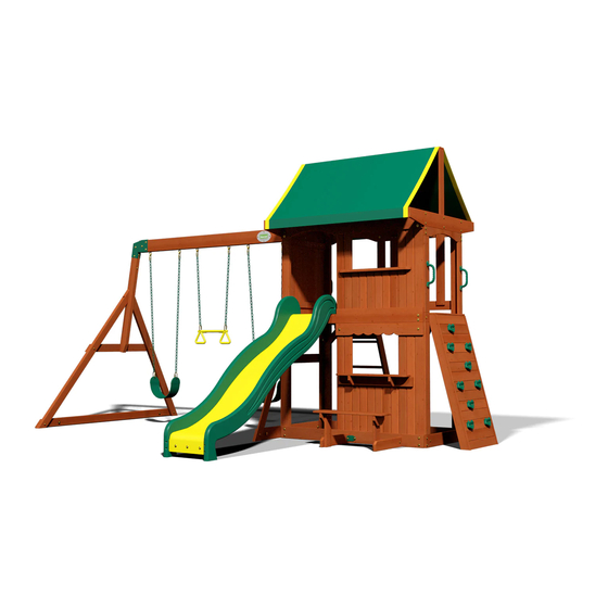
SOMERSET
Wooden Swing Set
Model: #65012
fastening system.
Made in China
Advertisement
Table of Contents

Related Manuals for Backyard Discovery SOMERSET 65012


Summary of Contents for Backyard Discovery SOMERSET 65012
- Page 1 Model: #65012 • Owner's Manual • Frequently Asked Questions • Assembly Instructions • Warranty Information Manufacturer: Backyard Discovery 3001 North Rouse Pittsburg, KS 66762 1-800-856-4445 Register your new swing set on-line @ www.swingsetsonline.com (you will also find any updates on assembly instructions and...
- Page 2 STOP PARE Missing A Part? CALL US BEFORE GOING BACK TO THE STORE! The store where you made your purchase does not stock parts for this item. If you have assembly questions or if you need parts, whether they are missing or damaged Call Toll-Free Help Line or visit www.swingsetsonline.com ¡LLÁMENOS ANTES DE REGRESAR A LA TIENDA! La tienda donde realizó...
-
Page 3: For Your Records
Owner’s Manual Play Set Dear Customer: Please read entire booklet completely before beginning the assembly process. Equipment is recommended for use by children 3 to 10 years of age. Structures are not intended for public use. The Company does not warranty any of its residential structures subjected to commercial use such as: Daycare, Preschool, Nursery School, Recreational Park, or any similar Commercial Application. -
Page 4: Positioning Your Playcenter
Owner’s Manual Play Set Please refer to the Assembly section of the Assembly Manual for Maximum Fall Height. Positioning Your Playcenter 1. The Playcenter is designed to be installed on a level surface by an Adult with an Adult helper. Place in a flat area of your yard to minimize ground preparation. 2. - Page 5 Owner’s Manual Play Set The following chart explains the fall height in feet from which a life threatening head injury would not be expected Critical Heights in feet (m) of Tested Materials Material Uncompressed Depth Compressed Depth 6" (152mm) 9" (228mm) 12"...
-
Page 6: Maintenance Instructions
Owner’s Manual Play Set 18. Verify that any suspended climbing ropes, chain, or cable are secured at both ends and that they cannot be looped back on it. 19. Instruct children not to attach items to the playground equipment that are not specifically designed for use with the equipment, such as, but not limited to, jump ropes, clothesline, pet leashes, cables and chain as they may cause a strangulation hazard. -
Page 7: Disposal Instructions
Third Party Assembly: Customer may, in their sole discretion, elect to use a third party person or service to assemble this product. Backyard Discovery assumes no responsibility or liability for any charge incurred by the Customer for any assembly services’. - Page 8 Owner’s Manual Play Set APPENDIX A Information on Playground Surfacing Materials: The following information is from the United States Consumer Product Safety Commission’s Information Sheet for playground surfacing material; also see the following website for additional information: www.cpsc.gov/cpscpub/pubs/323.html. X3. SECTION 4 OF THE CONSUMER PRODUCT SAFETY COMMISSION’S OUTDOOR HOME PLAYGROUND SAFETY HANDBOOK X3.1 Select Protective Surfacing—One of the most important things you can do to reduce the likelihood of serious head injuries is to install shock-absorbing protective surfacing under and around your play equipment.
- Page 9 Owner’s Manual Play Set The American Society for Testing and Materials takes no position respecting the validity of any parent right asserted in connection with any item mentioned in this standard. Users of this standard are expressly advised that determination of the validity of any such parent rights, and the risk of infringement of such rights, are entirely their own responsibility.
- Page 10 11. The end beam is not straight up and down. Why not? This is normal. Backyard Discovery designs playsets this way to ensure the strongest structure possible. The slight angle adds strength and reduces rocking and twisting.
-
Page 11: Tools Required For Installation
Tools Required for Installation: (These are the tools that are generally required for assembly of our outdoor products. These tools are not included with the outdoor product purchase.) (Square) (Level 24") (Claw Hammer) (Phillips Screw Driver) (Tape Measure) (Drill Attachments: Socket Driver) (1/8"... - Page 12 Basic Setup Dimensions Place the set on level ground, not less than 6 ft [2 m] from any structure or obstruction such as a fence, garage, house, overhanging branches, laundry lines, or electrical wires. 15'-3 7/8" [4.7] 10'-9 5/8" [3.3] [1.8] Safe Play Zone General Information:...
-
Page 13: Parts Identification
Parts Identification Wood Components (NOT TO SCALE) E1 - UPRIGHT - W101261 1 3/8"x3 3/8"x81 3/4" (36x86x2076) E2 - UPRIGHT - W101260 1 3/8"x3 3/8"x81 3/4" (36x86x2076) E3 - UPRIGHT - W101256 1 3/8"x3 3/8"x81 3/4" (36x86x2076) E77 - ANGLE BRACE - W100991 1 3/8"x3 3/8"x74 3/8"... - Page 14 Parts Identification Wood Components (NOT TO SCALE) H76 - LADDER RUNG - W100611 1"x3 3/8"x18 1/8" (24x86x460) H79 - END SUPPORT - W100992 1"x3 1/2"x42" (24x86x1072) H80 - GROUND BOARD - W100990 1"x3 3/8"x87 3/8" (24x86x2218) J1 - WINDOW LEDGE - W100709 1"x2 3/8"x29 1/2"...
- Page 15 Parts Identification Wood Components (NOT TO SCALE) K9-3 - WALL BOARD - W101257 3/8"x3 3/8"x42" (11x86x1068) K9-4 - WALL BOARD - W101239 3/8"x3 3/8"x37 3/8" (11x86x950) K9-5 - WALL BOARD - W101259 3/8"x3 3/8"x21 3/8" (11x86x544) L2 - GROUND BOARD - W100684 5/8"x4 3/8"x60 1/8"...
- Page 16 Parts Identification Wood Components (NOT TO SCALE) M5 - FACE BOARD - W101599 5/8"x3 3/8"x43 1/8" (16x86x1094) M6 - LOWER FACE BOARD - W101598 5/8"x3 3/8"x38 5/8" (16x86x982) M7 - WALL BOARD - W100708 5/8"x3 3/8"x35 1/4" (16x86x895) M8 - WALL RAIL - W100700 5/8"x3 3/8"x35 7/8"...
- Page 17 Parts Identification Wood Components (NOT TO SCALE) M77 - SLIDE BRACE - W100544 5/8"x3 3/8"x17 1/4" (16x86x438) M78 - CENTER SLIDE BRACE - W100545 5/8"x3 3/8"x17 1/4" (16x86x438) M81 - ROCK WALL BOARD - W101130 5/8"x3 3/8"x22 3/8" (16x86x568) M82 - ROCK WALL BOARD - W4L05551 5/8"x3 3/8"x22 3/8"...
- Page 18 Parts Identification Hardware (11) AA - LAG SCREW WH 5/16x2 1/2 - H100028 AY - BOLT PTH 1/4x1 - H100061 (32) Z - LAG SCREW WH 5/16x2 - H100027 (26) BE - T-NUT 1/4 - H100072 (20) BG - T-NUT 5/16 - H100074 (11) CM - BOLT WH 5/16x1/2 - H100115 (48)
- Page 19 Parts Identification Hardware (28) CG - WASHER LOCK INT 8x15 - H100108 (13) CT - SCREW TAPPING 8x1/2 - H100123 (15) CE - WASHER FLAT 9x18 - H100106 CH - SCREW TAPPING 14x1-1/2 - H100109 - T-40 TORX WRENCH - A100041 (60) BN - SCREW PFH 8x1 - H100085 (50)
- Page 20 Parts Identification Hardware (19) BA - BOLT PTH 1/4x3/4 - H100063 KY - BOLT WH 1/4x1/2" - H100141 - T-30 TORX BIT - H100147 KT - BOLT WH 1/4x1 - H100137 C - NUT BARREL WH 5/16x1 1/2 - H100006 KW - WASHER LOCK EXT 8x15 - H100139 KS - NUT BARREL WH 1/4x5/8 - H100136...
- Page 21 Parts Identification Accessories (NOT TO SCALE) EK - SLIDE RAIL 8' GREEN RIGHT - A100054 - TRAPEZE - A6P00034 EL - SLIDE RAIL 8' GREEN LEFT - A100055 HC - BYD ID TAG (LARGE) 2011 WITH FA - QUICK LINK AGES EM - SLIDE BED 8' YELLOW - A100056 -A100069...
- Page 22 Parts Identification Accessories (NOT TO SCALE) - GREEN HC ROCK #1 - A6P00036 - BLUE HC ROCK #2 - A6P00040 - GREEN HC ROCK #2 - A6P00037 - BLUE HC ROCK #1 - A6P00041 - RED HC ROCK #1 - A6P00038 - YELLOW HC ROCK #1 - A6P00042 - RED HC ROCK #2 - A6P00039 - YELLOW HC ROCK #2 - A6P00043...
- Page 23 SB74 - SWING BEAM EXTENDED - W102419 2"x5 1/4"x89 1/2" (50x134x2274) GD - L BRACKET 66x66x127 - A100140 TC - SWING BEAM EXTENSION BRACKET-RIGHT - A100326 TB - SWING BEAM EXTENSION BRACKET-LEFT - A100325 4 FT GREEN EXTENDED SWING BEAM WITH TRAPEZE BOLT WH 5/16x1-3/4...
- Page 24 E77 - ANGLE BRACE - W100991 W71 - SWING BEAM SUPPORT - W102420 1 3/8"x3 3/8"x74 3/8" (36x86x1890) 2"x3 3/8"x49 5/8" (50x86x1260) H79 - END SUPPORT - W100992 H80 - GROUND BOARD - W100990 1"x3 1/2"x42" (24x86x1072) 1"x3 3/8"x87 3/8" (24x86x2218) STEP 2 ATTACH H80 GROUND BOARD TO (2) E77 ANGLED SUPPORT BOARDS USING 2"...
- Page 25 STEP 3 INSERT W71 BOARD INTO TB AND TC BRACKET OPENING AND SECURE USING 1-3/4" BOLTS AND 7/8" BARREL NUTS, AS BOLT WH SHOWN. 5/16x1-3/4 BOLT WH 5/16x2-1/2 INSERT 2-1/2" BOLTS, LOCK WASHERS AND 1-1/2" BARREL NUTS INTO THE EDGE OF W71 BOARD, AS SHOWN.
- Page 26 STEP 4 INSERT (6) SWING HANGER QUICK LINK INTO SB74 SWING BEAM USING SAFETY NUT LOCK 5/16 WASHERS, FLAT WASHERS AND 5/16" LOCK NUTS, AS SHOWN. WASHER FLAT 8x27 SB74 WASHER SAFETY 17x30 SWING HANGER QUICK LINK SB74...
-
Page 27: Slide Assembly
M77 - SLIDE BRACE - W100544 5/8"x3 3/8"x17 1/4" (16x86x438) EM - SLIDE BED 8' YELLOW - A100056 SLIDE ASSEMBLY STEP 1 T-NUT 5/16 BOLT WH 5/16x1/2 SLIDE BED 8' YELLOW (1 PLC) BOLT WH 5/16x1/2 (3 PLCS) T-NUT 5/16 (3 PLCS) USE 'M77' SLIDE BRACE AS A TEMPLATE FOR DRILLING BOTTOM... - Page 28 EL - SLIDE RAIL 8' GREEN LEFT - A100055 EK - SLIDE RAIL 8' GREEN RIGHT - A100054 M78 - CENTER SLIDE BRACE - W100545 5/8"x3 3/8"x17 1/4" (16x86x438) SLIDE ASSEMBLY STEP 2 SCREW PFH (24) 8x2 1/2 NOTE: MAKE CERTAIN SUPPORTS AND SLIDE BED ARE FULLY ENGAGED WITHIN...
-
Page 29: Start Here
M82 - ROCK WALL BOARD - W4L05551 E82 - LEFT RAIL - W101127 5/8"x3 3/8"x22 3/8" (16x86x568) 1 3/8"x3 3/8"x48 3/4" (36x86x1239) M83 - ROCK WALL BOARD - W101132 5/8"x3 3/8"x22 3/8" (16x86x568) E83 - RIGHT RAIL - W101128 M83 - ROCK WALL BOARD - W4L05552 1 3/8"x3 3/8"x48 3/4"... - Page 30 N72 - ROCK WALL END BOARD - W101129 5/8"x2 3/8"x23 5/8" (16x60x600) 4 FT ROCK WALL ASSEMBLY STEP 2 USING N72 ROCK WALL ENDBOARD AS A TEMPLATE, PILOT DRILL USING 1/8" DRILL BIT AND ATTACH N72 TO TOP OF E82 AND E83 UPRIGHT RAILS USING (2) 1-1/2" WOOD SCREWS, AS SHOWN.
- Page 31 - BLUE HC ROCK #1 - A6P00041 - YELLOW HC ROCK #1 - A6P00042 - RED HC ROCK #2 - A6P00039 - GREEN HC ROCK #1 - A6P00036 - GREEN HC ROCK #2 - A6P00037 - RED HC ROCK #1 - A6P00038 - YELLOW HC ROCK #2 - A6P00043 - BLUE HC ROCK #2 - A6P00040 4 FT ROCK WALL ASSEMBLY...
- Page 32 4 Ft Ladder Phase 1 & 2 Phase Notes DESCRIPTION LABEL • Assemble with hardware as shown. LEFT UPRIGHT • Center rungs in rail grooves. LADDER RUNG SCREW PFH 8x2 SCREW PFH 8x2 DESCRIPTION LABEL RIGHT UPRIGHT SCREW PFH 8x2 SCREW PFH 8x2...
-
Page 33: Rear Support
4 Ft Ladder Phase 3 Phase Notes • Assemble with hardware as shown. SCREW PFH 8x2 DESCRIPTION LABEL REAR SUPPORT SCREW PFH 8x2... - Page 34 M13 - FLOOR RAIL - W102867 E1 - UPRIGHT - W101261 K4 - FLOOR RAIL - W103700 5/8"x3 3/8"x60 1/8" (16x86x1528) 1 3/8"x3 3/8"x81 3/4" (36x86x2076) 5/8"x5 1/4"x60 1/8" (16x134x1528) E2 - UPRIGHT - W101260 M7 - WALL BOARD - W100708 M8 - WALL RAIL - W100700 L2 - GROUND BOARD - W100684 1 3/8"x3 3/8"x81 3/4"...
- Page 35 M10 - SAFETY BOARD - W100701 M9 - ANGLE BRACE - W100696 K1 - ROOF SWING BEAM SUPPORT - W100682 5/8"x3 3/8"x33 7/8" (16x86x860) 5/8"x3 3/8"x35 5/8" (16x86x904) 5/8"x5 1/4"x51 5/8" (16x134x1310) M5 - FACE BOARD - W101599 L3 - GROUND BOARD - W101602 K5 - FLOOR RAIL - W103705 5/8"x3 3/8"x43 1/8"...
- Page 36 M6 - LOWER FACE BOARD - W101598 L5 - GROUND BOARD - W100686 K2 - ROOF SUPPORT - W100683 5/8"x3 3/8"x38 5/8" (16x86x982) 5/8"x4 3/8"x30" (16x112x762) 5/8"x5 1/4"x51 5/8" (16x134x1310) M12 - ROCK WALL ARCH BOARD - W102862 M14 - FLOOR SUPPORT BOARD - W102864 M11 - UPPER FACE BOARD - W102866 5/8"x3 3/8"x30"...
- Page 37 M3 - TARP SUPPORT - W100692 SP1 - FLOOR SUPPORT CLEAT - W100711 5/8"x3 3/8"x60 1/8" (16x86x1528) 1"x1"x53 3/8" (24x24x1356) J2 - END FLOOR CLEAT - W100710 1"x2 3/8"x3 3/8" (24x60x86) J3 - FLOOR JOIST - W100984 F71 - STANDARD ANGLE BRACE - W100689 1"x2 3/8"x60 1/8"...
- Page 38 M16 - TARP SUPPORT - W101237 M1 - TENT SUPPORT - W101601 5/8"x3 3/8"x29 1/8" (16x86x740) 5/8"x3 3/8"x59 1/4" (16x86x1504) M4 - TARP TOP SUPPORT - W100693 L9 - END FLOOR BOARD - W102863 (3) FP1- FLOOR PANEL - W102861 5/8"x3 3/8"x60 1/8"...
- Page 39 J1 - WINDOW LEDGE - W100709 1"x2 3/8"x29 1/2" (24x60x750) K9-1 - WALL BOARD - W100713 3/8"x3 3/8"x15 3/4" (11x86x400) K9-2 - WALL BOARD - W100712 3/8"x3 3/8"x30 1/4" (11x86x768) STEP 7 WORKING YOUR WAY LEFT TO RIGHT, ATTACH (2) K9-2 WALL BOARDS TO K4 FLOOR RAIL AND L7 SCULPTURED RAIL USING (8) 1"...
- Page 40 (2) WP1 - WALL PANEL - W102865 STEP 8 CENTER AND ATTACH (2) WP1 WALL PANELS TO K1 SUPPORT AND K5 FLOOR RAIL USING (28) 1-1/8" WOOD SCREWS, AS SHOWN. SCREW PFH (28) 8x1 1/8 ASSEMBLER MAY HAVE TO LOOSEN OR REMOVE BOLTS AND BARRELS TO INSTALL WP1 PANELS.
- Page 41 M17 - PICKET - W100705 5/8"x3 3/8"x27 1/8" (16x86x690) STEP 9 ATTACH (4) M17 PICKETS TO M8 WALL RAIL AND L6 ARCHED RAIL USING (16) 1-1/8" WOOD SCREWS, AS SHOWN. SCREW PFH (16) 8x1 1/8 3 1/8" TYP (5 SPCS) 2 1/4"...
- Page 42 K9-4 - WALL BOARD - W101239 H1 - SERVING SHELF SUPPORT - W101604 K3 - SERVING BOARD - W101605 3/8"x3 3/8"x37 3/8" (11x86x950) 1"x3 3/8"x30 3/4" (24x86x780) 5/8"x5 1/4"x28 3/4" (16x134x729) H3 - SERVING BOARD SUPPORT - W101606 1"x3 3/8"x3 3/8" (24x86x86) L8 - SCULPTURED RAIL - W101240 K9-3 - WALL BOARD - W101257 K9-5 - WALL BOARD - W101259...
- Page 43 EA - HAND GRIP YELLOW PLASTIC - A100043 STEP 12 INSERT (2) 1/4" T-NUTS INTO INSIDE SURFACE OF M7 AND M11 WALL BOARD, AS SHOWN. NEXT, ATTACH EA HANDLE GRIP TO M7 WALL BOARD USING (2) 1" PTH BOLTS, LOCK BOLT PTH 1/4x1 WASHERS AND FLAT WASHERS, AS SHOWN.
- Page 44 HY - TARP 1522x2119 - A100062 1/32"x59 7/8"x83 3/8" (.4x1522x2119) STEP 13 CENTER HY TARP OVER M4 TARP TOP SUPPORT AND ATTACH USING (4) 1/2" TAPPING SCREWS, AS SHOWN. NEXT, DRAPE HY TARP EVENLY OVER (2) M3 TARP SUPPORTS AND WRAP UNDERNEATH AND UP THE BACK SIDE OF M3 SUPPORT APPROXIMATELY 1-13/16"...
- Page 45 H4 - BENCH SEAT SUPPORT - W104040 M2 - BENCH SEAT - W104044 1"x3 3/8"x6 1/2" (24x86x166) 5/8"x3 3/8"x27 3/8" (16x86x694) EJ - L BRACKET 54x67 - A100053 H6 - BENCH GROUND BOARD - W104042 H5 - BENCH UPRIGHT - W104041 1"x3 3/8"x18 1/8"...
- Page 46 (1) - BENCH ASSEMBLY STEP 15 USING BENCH ASSEMBLY BRACKETS AS A TEMPLATE, DRILL TWO 10MM THRU HOLES AND ATTACH EJ BRACKET TO L2 GROUND BOARD USING (2) BOLT WH 5/16x1/2 1/2" BOLTS, LOCK WASHERS AND 5/8" BARREL NUTS, AS SHOWN. WASHER LOCK EXT 12x19...
- Page 47 (1) - SLIDE ASSEMBLY STEP 16 CENTER THE WAVE SLIDE ASSEMBLY IN OPENING, AS SHOWN. BOLT WH 5/16x1/2 USING A 10MM DRILL BIT, DRILL THREE THROUGH HOLES INTO THE SLIDE BED AND DECK BOARDS, AS SHOWN BELOW. ATTACH THE SLIDE ASSEMBLY TO THE DECK USING (3) 1/2" BOLTS, LOCK WASHERS AND 5/8"...
- Page 48 (1) - ROCK WALL ASSEMBLY STEP 17 ATTACH THE ROCK WALL ASSEMBLY TO M14 FLOOR BOARD SUPPORT USING (2) 2" LAG SCREWS AND LOCK WASHERS, AS SHOWN. CENTER ROCK WALL ON 'M14' BOARD AND PILOT DRILL 1/8" HOLES FOR ROCK WALL LAG SCREW ATTACHMENT.
- Page 49 (1) - LADDER ASSEMBLY STEP 18 ATTACH THE LADDER ASSEMBLY TO M13 FLOOR RAIL SUPPORT USING (2) 2-1/2" LAG SCREWS AND LOCK WASHERS, AS SHOWN. CENTER LADDER ON 'M13' BOARD AND PILOT DRILL 1/8" HOLES FOR LADDER ATTACHMENT. LAG SCREW WH 5/16x2 1/2 WASHER LOCK EXT...
-
Page 50: Swing Beam Assembly
(1) - SWING BEAM ASSEMBLY STEP 19 ATTACH SWING BEAM ASSEMBLY TO K1 ROOF SWING BEAM SUPPORT USING (4) 1" BOLTS, SPLIT WASHERS AND FLAT WASHERS, AS SHOWN SCREW PWH 8x5/8 BELOW. BOLT HEX 5/16x1 ATTACH HC I.D. TAG TO SB74 SWING BEAM USING (4) 5/8" PFH SCREWS, AS SHOWN. - Page 51 EZ - CHAIN GREEN 51.25" - A100068 FB - SWING SEAT YELLOW - A100070 KN - CHAIN GREEN 31" - A100177 - TRAPEZE - A6P00034 FA - QUICK LINK - A100069 STEP 20 ATTACH FB SWING SEAT TO (2) EZ CHAINS USING (2) FA QUICK LINKS, AS SHOWN (FIG. 1). REPEAT PROCESS TO ASSEMBLE SECOND SWING ASSEMBLY.
- Page 52 SS - "C" REVISION TAG - A100316 KC - METAL GROUND STAKE BROWN - A100178 ANCHORING INSTRUCTIONS NOTE: BOLT WH FAILURE TO USE GROUND STAKES CAN 1/4x1/2" VOID WARRANTY & CAUSE INJURY! BOLT WH 1/4x1 STAKE A STAKE A STAKE A WASHER LOCK EXT 8x15...
- Page 53 Limited Warranty. In addition, Backyard Discovery will replace any parts within the first 30 days from date of purchase found to be missing from or damaged in the original packaging.
Need help?
Do you have a question about the SOMERSET 65012 and is the answer not in the manual?
Questions and answers