Advertisement
Quick Links
Advertisement

Related Manuals for aero-naut Kalle 2


Summary of Contents for aero-naut Kalle 2
- Page 1 Kalle 2 Order-No. 3032/00...
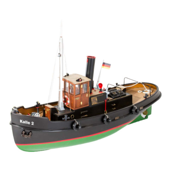
- Page 2 Thank you for buying an aero-naut kit! Kalle 2 is the model of a small steam tug which was in use in the 20ies and 30ies of the last century. This kit contains precisely laser-cut parts and a sheet of photo-etched brass parts for the fine details which give the model its realistic appearance.
- Page 3 Glue together keel parts 7 + 8 and keel extension parts 9 + 10. Glue together parts 4 - 6 to assemble the boat stand Trim the vacuum formed hull at the line indicated, leaving a ca. 10 - 20 mm wide rim. 7 mm Drill holes with a diameter of 7 and 4 mm into the rear end of...
- Page 4 When glue has dried completely, sand rudder to a drop-shaped cross- section. With a sanding block sand contact surface for keel parts smooth. 2 mm 2 mm Glue together rudder parts 11 - 14. Please note, that rudder stock 11 protrudes 2 mm at bottom end.
- Page 5 Place keel on hull, slide a Ø 3 mm brass rod through rudder sleeve 16 and into 3 mm hole in keel extension, but do not glue! 1 mm Check keel 7 for correct position, then glue in place with Stabilit Express (or similar). Insert rudder sleeve 16 in hull.
- Page 6 Glue together side panels 21, motor mount 19 and frame 20. Prepare motor mount 19 for motor installation. It is possible to install 500-type brushed motors or slow outrunners with a diameter of 28 mm. For 500-type brushed motors increase diameter of centre hole to 13 mm using a drill bit or a file (use engraved line on motor mount as a guide).
- Page 7 Temporarily install prop (diameter 50 mm) on prop shaft. There should be a space of about 5 mm between rudder and prop hub. 3 mm From the aero-naut range of accessories select a motor coupling which fits your prop shaft and motor shaft diameters.
- Page 8 Glue together servo tray brackets 27 + 28, then glue to servo tray 29. Use screws 15 to install servo tray on sub-deck assembly.
- Page 9 Cut off excess material as indicated from vacuum formed deck assembly. Turn deck assembly upside down and fit deck 30 in place. Use a sharp scalpell and scratch along the inside of the bulwark several times with only little pressure. Then carefully break off excess material.
- Page 10 Glue support frame 31 for rudder linkage access hatch cover to the underside of deck 30. Glue deck 30 onto the hull´s contact surface. Glue coaming parts 32 + 33 into deck opening.
- Page 11 Glue bulwark 2 onto deck. 180 mm 310 mm Position template S1 on bulwark as shown, draw contour of wash port onto bulwark with a soft pencil, then use drill bit and file to cut out wash port.
- Page 12 Drill three 1.5 mm holes for fender ropes into Glue wash ports 140 in place. bulwark. The tire fenders 138 will be tied to the hull at a later stage. Ø 1,5 mm Ø 1,5 mm Ø 1,5 mm 95 mm Clean the hull with warm water and a mild detergent, then lightly sand with wet sanding paper (600 grade or higher).
- Page 13 In the bow slide part 37 to foremost position 36.2 and glue onto centre line of deck. Glue support 38 to underside of part 39, the glue assembly onto part 37 and deck. Slide bracket 36.1 onto bollard 36.2. 36.1 Glue bollard onto deck with base ring 36 and from below glue bracket 36.1 to handrail of bulwark.
- Page 14 Install rudder servo in servo tray and secure with screws. Install connector 35 on servo arm. Install connector 35 on rudder control horn 34. Slide pushrod 156 into connectors, cut to length and secure.
- Page 15 Use template S2 to cut out the portholes and to drill four holes with a diameter of 0.5 mm. Cut out superstructure as indicated by red line on picture. Ø 0,5 mm Cut out skylights in such a way, that hatch covers 55 still fit over openings.
- Page 16 50.2 50.2 50.2 Assemble and glue together two cowl ventilators 54. 50.1 Determine orientation and hight of ventilators, then glue in place ventilators and collars. Note: To be able to rotate ventilators any time, just glue collars to ventilators at proper hight and insert ventilators in roof of superstructure.
- Page 17 Glue together three parts 62 to make up the mast. Slide mast ring 66 onto mast and glue Drill two 0.5 mm holes into funnel 56 Sand mast to a circular in place. Wrap eye band 75 around mast and glue in place steam pipe brackets cross section above the and glue in place.
- Page 18 Assemble and glue together Glue together wheel column parts 85. From shelves 82, then glue brass wire 89 form a ring with a diameter of assembled shelves into front Apply one coat of sanding sealer to inside and outside of 39.5 mm and glue around wheel.
- Page 19 Place wheelhouse on superstructure, but do not glue. Glue trim panels 91 + 94 to wheelhouse base, so that they fit around superstructure and hold wheelhouse in place. Remove wheelhouse, apply a second coat of sanding sealer, Glue window panes 95 - 97 sand lightly and apply a coat in place with glue suitable for of clear varnish.
- Page 20 Carefully round off edges of life belt 108, apply two coats of sanding sealer, then paint. Glue rope 109 to life belt in four places as illustrated. Cut off suitable pieces of fabric 110 and glue to life belt. Install llife belt in brackets 107 at front of wheel house. Glue port holes 143 onto boiler house hatch covers.
- Page 21 Bend photo etched part 117 along etchd lines to form shovel. Round off handle 118 of coal shovel and glue to shovel. Glue brackets 119 into superstructure and install shovel in brackets. 1 : 1 Glue in place rivet strips 126 + 127 and with Tie photo etched hooks 129 to 3 mm drill holes for tow rope guard 120.
- Page 22 Glue or solder eye 131 to top of flagpole 130, glue or solder cleat 132 to lower end of flagpole 130. Attach thread 155 to eye and cleat and attach flag 133 to thread. 130.1 Glue together windlass base parts 142 and 143. Glue in place supports 144.
- Page 23 1 : 1 Bend tow rope guard 136 as illustrated and glue into deck. Attech tire fenders 138 to bulwark with thread. Glue windlass onto deck. Glue anchor 154 into anchor pocket.
-
Page 24: Completing The Model
Make sure that hull, propeller shaft and rudder tube are watertight. If water enters hull, identify leak and repair. Have fun with your model of the Kalle 2. - Page 25 Description Pcs. Material Sheet Form Dimensions Remarks Description Pcs. Material Sheet Form Dimensions Remarks funnel/ventilator deck plywood laser-cut 0.8 mm hull styrene vacuum formed bulwark styrene vacuum formed tow hook assembly plastic tube cut part 7/6 x 78 mm cut from Z1 superstructure styrene vacuum formed...
- Page 26 Description Pcs. Material Sheet Form Dimensions Remarks Description Pcs. Material Sheet Form Dimensions Remarks nav light board plywood laser-cut 0.8 mm 148 gear wheel plywood laser-cut 2 mm 100 nav light board plywood laser-cut 0.8 mm 149 shaft brass wire cut part 1.5 x 50 mm cut from Z2...
-
Page 27: Photo-Etched Parts
Photo-etched parts 137.1 actro-n Brushless motors aero-naut servos Digital and analog servos for your model (8-20 mm) actro-n 28-3 1300 kV actro-n 35-4 1100 kv actro-n 50-2 760 kv actro-n 28-4 880 kv actro-n 35-4 790 kv actro-n 50-3 435 kv... - Page 28 Laser-cut wood kit with many photo-etched brass parts and many additional options for the ambitious modeller. aero Scale ca. 1:20 naut Length ca. 710 mm Beam ca. 230 mm aero-naut Modellbau Stuttgarter Strasse 18-22 D-72766 Reutlingen Find many more at www.aero-naut.com www.aero-naut.de...
Need help?
Do you have a question about the Kalle 2 and is the answer not in the manual?
Questions and answers