Advertisement
Quick Links
Advertisement

Subscribe to Our Youtube Channel
Related Manuals for aero-naut Quido


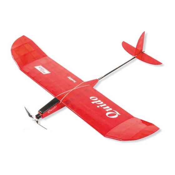
Summary of Contents for aero-naut Quido
- Page 1 Electric Model Aeroplane Quido Order-No. 1303/00...
-
Page 2: Technical Data
With the exception of the tail end of the fuselage, which is a carbon tube, and spruce spars Quido is a pure balsa model. The result is a light-weight yet strong model. A 2S-LiPo and an outrunner with 100 to 150 Watts are recommended to power the Quido. In addtion you´ll need basic 3-channel radio equipment with two micro servos and a speed controller. - Page 3 The wing spar is a lamination of three spruce spars. Mark the centre on all three spars and glue spars together as shown. Secure spars with tape or clamps until glue has dried completely. Remove any residual glue and carefully sand surface of spar. Sort ribs according to cross-section of spar and slide ribs on spar.
- Page 4 Place spar with ribs on Depron jig and glue ribs to spar. Glue in place upper wing spars 25 and lower trailing edge sheeting 37. Glue leading edge 27 to the front of ribs and glue in place balsa gussets: glue front gussets to groove in leading edge and rear gussets to top of trailing edge sheeting.
- Page 5 Remove centre wing panel from jig and turn upside down. Cut off tabs with modeller´s knife or razor saw and glue in place lower centre wing sheeting 36. Build up the outer wing panels. Insert ribs 33 to 35 into wing jigs and glue in place spars 26 and lower trailing edge sheeting 38.
- Page 6 Trim off spars and sheeting material at end ribs and position wing tips 39 at end ribs (do not glue!). Cut leading edge parts 28 to correct angle and length and glue to front of ribs. Glue in place plywood gussets 45 and upper trailing edge sheeting 38.
- Page 7 Trim off upper trailing edge sheeting material, then sand leading edges and wing tips to shape. Ribs with a triangular cross-section are used for correct dihedral of outer wing panels. Glue one rib 40 each flush with underside of wing panels to centre wing panel and to wing tips.
- Page 8 Glue outer wing panels to centre wing panel and secure with clamps or tape. After a careful sanding the wing is ready to cover.
- Page 9 Glue the 6 formers together as shown and make sure the apertures and outer contours match perfectly. Cut 5×5 mm balsa stripwood 13 to a length of 210 mm and build up a box structure using the two central fuselage formers, wing supports 11 and balsa stripwood 13.
- Page 10 Glue built-up structure to fuselage side 1. Make sure that contours for wing saddle match perfectly and that rear end of fuselage side is flush with contact surface of formers 5 and 6. The lower end of the fuselage side should stand proud of the stripwood by about 2 mm where the lower fuselage sheeting will be fitted later on.
- Page 11 Cut to length lower fuselage sheeting material 42 from 2 mm balsa and glue in place. Attention: Sheeting material ends exactly at the contact surface of formers 3 and 4!
- Page 12 Glue 5×5 mm balsa stripwood 12 to lower front fuselage sheeting 10 (2 mm balsa) as shown. Slightly bevel rear end of lower front fuselage sheeting and fit sheeting in place.
- Page 13 Glue doubled-up motor mount 2 in place together with lower fuselage sheeting 10 and secure with tape until dry. Then glue in place remaining 5×5 mm balsa stripwood. Attention: The rectangular cutout in motor mount 2 needs to face upward! Trim stripwood flush with front of motor mount and sand lightly.
- Page 14 From the rear insert carbon tube 14 in fuselage and through motor mount. The carbon tube is used to align the 4 parts that form the rear end of the fuselage. Slightly bevel gluing surfaces of parts 8 (2 mm balsa) and glue to fuselage, resting opposite end of parts 8 on carbon tube.
- Page 15 When glue has dried, remove tube from fuselage and sand fuselage to a smooth finish, rounding off rear end of fuselage and lower fuselage edges. Sand contact surfaces for front fuselage cover, secure fuselage cover 21 in place with tape and round off the edges.
- Page 16 Insert snakes 15 into fuselage and secure with epoxy or CA in holes of rear fuselage formers.
- Page 17 From the rear insert carbon tube in fuselage and through hole in rear fuselage former. The carbon tube should protrude from the former by 5 mm. Align stabilizer horizontally and glue carbon tube into fuselage. Secure snakes on top of carbon tube until 5 cm from front edge of stabilizer. Use either small cut-offs of snake outer 52 or secure snakes with tape.
- Page 18 Slide small GRP control horn 49 onto carbon rod 47. Cut or file a groove into the front edges of the elevator halves and connect them with the rod. For correct spacing place elevator halves next to horizontal stabilizer. With epoxy glue control horn to one elevator half at an angle of 90°.
- Page 19 At correct angle press large GRP control horn 48 approximately 1 cm above lower edge of rudder 18 into rudder and glue with CA or epoxy. For correct angle place rudder next to fin and mark position of snake on rudder. Install servos in servo tray 41 and glue servo tray into fuselage.
-
Page 20: Completing The Model
Completing the Model Make a Z-bend at one end of control wires 16. From the fuselage side insert wires into snakes and connect wires to servo contol horns. Attach control surfaces to fin and elevator with tape. Use solder extenders 50 and clevises 51 to connect control wires to rudder and elevator. -
Page 21: First Flight
Select a calm day with little wind for your first flight. Hand-start the model into the wind with 50 % power and a slight nose-up attitude. Allow Quido to climb to a save hight, then trim model for straight and level flight. - Page 22 Description Pieces Material Description Pieces Material fuselage side 3 mm balsa rib, centre panel 2.5 mm balsa motor mount 3 mm balsa rib, centre panel 2.5 mm balsa former 3 mm balsa rib, outer panel 2.5 mm balsa former 3 mm balsa rib, outer panel 2.5 mm balsa former...
- Page 24 ... and some more models from our range Rocky 1350/00 ARC wood kit aero naut aero-naut Modellbau Luxx 1327/00 Stuttgarter Strasse 18-22 Lasercut wood kit D-72766 Reutlingen Find many mor at www.aero-naut.de www.aero-naut.de...
Need help?
Do you have a question about the Quido and is the answer not in the manual?
Questions and answers