Table of Contents
Advertisement
Quick Links
*15G065096001AK*
P/N: 15G065096001AK V1.1
Quick Installation Guide
C3758D4I-4L / C3558D4I-4L
The server board User's Manual is available for download from the ASRock Rack's official website
at http://www.asrockrack.com.
Take note of the following precautions before you install server board components or change any
server board settings.
1.
Unplug the power cord from the wall socket before touching any components.
2.
To avoid damaging the server board's components due to static electricity, NEVER place your
server board directly on the carpet or the like. Also remember to use a grounded wrist strap or
touch a safety grounded object before you handle the components.
3.
Hold components by the edges and do not touch the ICs.
4.
Whenever you uninstall any component, place it on a grounded anti-static pad or in the bag
that comes with the component.
5.
When placing screws into the screw holes to secure the server board to the chassis, please do
not over-tighten the screws! Doing so may damage the server board.
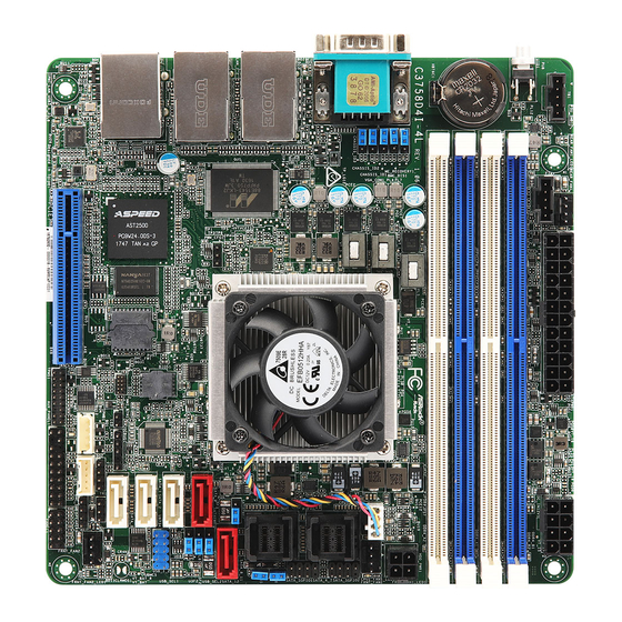
Motherboard Layout
2
1
40
1
REAR_FAN1
T 1
B
1
PSU_SMB1
UID
CMOS
Battery
39
38
1
ME_RECOVERY1
BMC_DIS1
1
37
1
CHASSIS_ID1
1
CHASSIS_ID2
CHASSIS_ID3
1
36
35
LAN1
LAN2
Marvell
LAN3
LAN4
USB 3.0
IPMI
T: USB2
LAN
B: USB1
34
3
I/O Panel
2
1
3
No. Description
1
UID Switch (UID)
2
COM Port (COM1)
3
VGA Port (VGA1)
4
LAN RJ-45 Port (LAN2)
5
LAN RJ-45 Port (LAN1)
2
3
17.0cm (6.7 in)
ATXPWR1
DDR4_B1 (
DDR4,
64 bit, 288-pin module, Blue)
DDR4_B2 DDR4,
(
64 bit, 288-pin module, White)
DDR4_A1 DDR4,
(
64 bit, 288-pin module, Blue)
DDR4_A2 DDR4,
(
64 bit, 288-pin module, White)
C3758
C3558
1543
BIOS
ROM
BMC
AST2500
PCIE7
(ME x8, EE x8)
1
33
32
31
4
6
8
5
7
9
No. Description
6
LAN RJ-45 Port (LAN4)
7
LAN RJ-45 Port (LAN3)
8
Dedicated IPMI LAN Port
USB 3.0 Ports (USB3_12)*
*The USB3_2 port on the rear I/O is shared
9
with the USB_1_2 header on the motherboard.
(Default is set to the USB_1_2 header.)
1
Install the Server Board
1
Insert the server board into the chassis.
2
A f f i x t he screws clock w ise into t he
mounting holes in all of the corners of
the server board.
Do not over-tighten the screws
4
DC_IN12V1
HDD_PWR1
FRNT_FAN1
CPU1_FAN1
SATA_4_7
SATA_8_11
SATA_PWR2
SATA_12
SATA_0
SATA_PWR1
SATA_1
USB_SEL2
USB_SEL1
SATA_2
1
SATA_3
USB_1_2
1
CLRMOS1
NMI_BTN1
1
1
LED_LAN3_4
T 1
R
1
1
1
SPEAKER1
FRNT_FAN2
BMC_SMB_1
IPMB1
AUX_PANEL1
1
1
TPMS1
PANEL1
30
29
28
4
Jumper Cap On/Off
When the jumper cap is placed on the pins, the
jumper is "Short". If no jumper cap is placed on the
pins, the jumper is "Open".
The illustration shows a 3-pin jumper whose pin1
and pin2 are "Short" when a jumper cap is placed on
these 2 pins.
www.asrockrack.com
C3758D4I-4L
No. Description
1
PSU SMBus (PSU_SMB1)
2
Rear Fan Connector (REAR_FAN1)
3
ATX Power Connector (ATXPWR1)*
4
ATX 12V Power Connector (DC_IN12V1)*
5
2 x 288-pin DDR4 DIMM Slots (DDR4_A1 DDR4_B1)
5
6
2 x 288-pin DDR4 DIMM Slots (DDR4_A2, DDR4_B2)
7
HDD Power Connector (HDD_PWR1)
6
8
CPU Fan Connector (CPU1_FAN1)
9
Front Fan Connector (FRNT_FAN1)
10
SATA SGPIO Connector (SATA_SGPIO1)
7
11
Mini SAS HD Connector (SATA_4_7)
8
9
12
SATA SGPIO Connector (SATA_SGPIO2)
13
Mini SAS HD Connector (SATA_8_11)
10
11
14
SATA DOM Power Jumper (SATA_PWR1)
12
15
SATA3 DOM Connector (SATA_12), Red
16
SATA3 DOM Connector (SATA_0), Red
13
17
SATA DOM Power Jumper (SATA_PWR1)
14
15
18
USB Selection Jumper (USB_SEL2)
16
17
19
USB Selection Jumper (USB_SEL1)
18
19
20
USB 2.0 Header (USB_1_2)**
20
21
Clear CMOS Pad (CLRMOS1)
21
22
23
22
Non Maskable Interrupt Button (NMI_BTN1)
24
25
23
LAN LED Connector (LED_LAN3_4)
26
27
24
Thermal Sensor Header (TR1)
25
Front Fan Connector (FRNT_FAN2)
26
Speaker Header (SPEAKER1)
27
BMC SMB Header (BMC_SMB1)
28
System Panel Header (PANEL1)
29
Auxiliary Panel Header (AUX_PANEL1)
30
TPMS Header (TPMS1)
31
Intelligent Platform Management Bus header (IPMB1)
32
SATA3 Connector (SATA_3), White
33
SATA3 Connector (SATA_2), White
34
SATA3 Connector (SATA_1), White
35
Chassis ID Jumper (CHASSIS_ID3)
36
Chassis ID Jumper (CHASSIS_ID2)
37
Chassis ID Jumper (CHASSIS_ID1)
38
Enable/Disable BMC Jumper (BMC_DIS1)
39
ME Recovery Jumper (ME_RECOVERY1)
40
Thunderbolt AIC Connector (TB1)
*Please use either the ATX 12V Power Connector (DC_IN12V1) or the ATX
Power Connector (ATXPWR1) at one time. Do not connect them both simutane-
ously.
** The USB3_2 port on the rear I/O is shared with the USB_1_2 header on the
motherboard. Please refer to the User Manual for jumper setup information.
C3558D4I-4L
Advertisement
Table of Contents

Related Manuals for ASROCK Rack C3758D4I-4L


Summary of Contents for ASROCK Rack C3758D4I-4L
- Page 1 C3758D4I-4L C3558D4I-4L Install the Server Board The server board User's Manual is available for download from the ASRock Rack's official website at http://www.asrockrack.com. Take note of the following precautions before you install server board components or change any Insert the server board into the chassis.
- Page 2 Quick Installation Guide C3758D4I-4L / C3558D4I-4L www.asrockrack.com C3758D4I-4L C3558D4I-4L Install the Power Cables LAN Port LED Indications LAN Port SPEED LED ACT/LINK LED LAN Port Speed LED Activity / Link LED Status Description Status Description 10Mbps connection or No Link...
Need help?
Do you have a question about the C3758D4I-4L and is the answer not in the manual?
Questions and answers