Rockwell Automation Allen-Bradley Kinetix 5500 Installation Instructions Manual
Hide thumbs
Also See for Allen-Bradley Kinetix 5500:
- User manual (260 pages) ,
- Questions and answers (10 pages) ,
- Selection manual (234 pages)
Table of Contents
Advertisement
Quick Links
Installation Instructions
Original Instructions
Kinetix 5500 Servo Drives
Catalog Numbers 2198-H003-ERS, 2198-H008-ERS, 2198-H015-ERS, 2198-H025-ERS, 2198-H040-ERS, 2198-H070-ERS,
2198-H003-ERS2, 2198-H008-ERS2, 2198-H015-ERS2, 2198-H025-ERS2, 2198-H040-ERS2, 2198-H070-ERS2
Topic
Summary of Changes
This publication contains new and updated information as indicated in the following table.
Topic
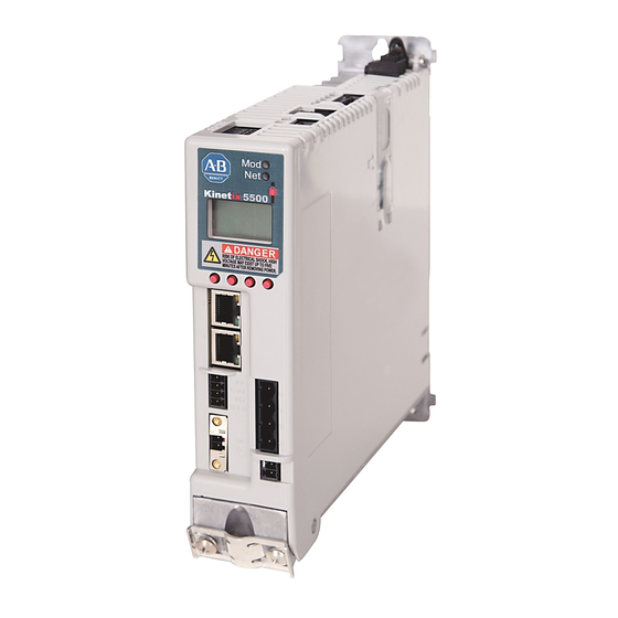
About the Kinetix 5500 Drives
Kinetix® 5500 servo drives provide an Integrated Motion over the EtherNet/IP network solution for applications with output power and current
requirements in the range of 0.2...14.6 kW and 1.4...32.5 A 0-pk, respectively.
See the Kinetix 5500 Servo Drives User Manual, publication 2198-UM001, for detailed information on wiring, applying power, troubleshooting,
and integration with ControlLogix® 5570, ControlLogix 5580, and GuardLogix® 5570, or CompactLogix™ 5370 and Compact GuardLogix 5370
controllers.
Page
1
1
2
2
2
3
6
9
10
12
14
15
Page
2...3
3
6
9
12...14
14
Advertisement
Table of Contents

Related Manuals for Rockwell Automation Allen-Bradley Kinetix 5500


Summary of Contents for Rockwell Automation Allen-Bradley Kinetix 5500
-
Page 1: Table Of Contents
Installation Instructions Original Instructions Kinetix 5500 Servo Drives Catalog Numbers 2198-H003-ERS, 2198-H008-ERS, 2198-H015-ERS, 2198-H025-ERS, 2198-H040-ERS, 2198-H070-ERS, 2198-H003-ERS2, 2198-H008-ERS2, 2198-H015-ERS2, 2198-H025-ERS2, 2198-H040-ERS2, 2198-H070-ERS2 Topic Page Summary of Changes About the Kinetix 5500 Drives Catalog Number Explanation Before You Begin Remove the Grounding Screws in Ungrounded Power Configurations Install the Kinetix 5500 Servo Drive Connector Data Wiring Requirements... -
Page 2: Catalog Number Explanation
Removing the grounding screws in multi-axis configurations is best done when the drive is removed from the panel and placed on its side on a solid surface that is equipped as a grounded static-safe workstation. ATTENTION: Because the unit no longer maintains line-to-neutral voltage protection, the risk of equipment damage exists when you remove the grounding screws. Rockwell Automation Publication 2198-IN001D-EN-P - February 2016... -
Page 3: Install The Kinetix 5500 Servo Drive
Because the system is of the open type construction, be careful to keep any metal debris from falling into it. Metal debris or other foreign matter can become lodged in the circuitry and result in damage to components. Rockwell Automation Publication 2198-IN001D-EN-P - February 2016... - Page 4 Zero-stack Tab and Cutout Aligned 2. Mount the Kinetix 5500 drive to the cabinet subpanel with M4 (#8-32) steel machine screws torqued to 2.0 N•m (17.7 lb•in), max. Rockwell Automation Publication 2198-IN001D-EN-P - February 2016...
- Page 5 Feedback Converter Kit Mounted on Frame 3 Drive Mounted on Frame 1 Drive Refer to Kinetix Servo Drives Technical Data, publication GMC-TD003, for motor/actuator compatibility with the 2198-H2DCK converter kit and product dimensions. Rockwell Automation Publication 2198-IN001D-EN-P - February 2016...
-
Page 6: Connector Data
2-position plug, spring terminals Brake power 2-position plug, terminal screws Digital inputs 4-position plug, spring terminals Safe torque off 5-position plugs, spring terminals, 2x (2 rows of 5 pins) PORT1, PORT2 Ethernet communication ports RJ45 Ethernet Rockwell Automation Publication 2198-IN001D-EN-P - February 2016... - Page 7 Cable shield and grounding plate (internal to 2198-KITCON-DSL connector kit) termination point SHIELD SHIELD Cable shield and shield clamp (internal to 2198-H2DCK converter kit) termination point (1) Refer to Kinetix 5500 Servo Drives User Manual, publication 2198-UM001, for installation instructions. Rockwell Automation Publication 2198-IN001D-EN-P - February 2016...
- Page 8 Port Pin Description Signal Transmit port (+) data terminal Transmit port (-) data terminal Standard RJ45 Receive port (+) data terminal – – – – Receive port (-) data terminal – – – – Rockwell Automation Publication 2198-IN001D-EN-P - February 2016...
-
Page 9: Wiring Requirements
• Use motor power connectors only for connection purposes. Do not use them to turn the unit on and off. • Ground shielded power cables to prevent potentially high voltages on the shield. Rockwell Automation Publication 2198-IN001D-EN-P - February 2016... -
Page 10: Attach The Motor Cable Shield Clamp
Shield Clamp Shield Clamp Screws (2) 2090-CSBM1DF-14AAxx Single Motor Cable IMPORTANT When the drive/motor combination calls for 14 or 10 AWG cable, the feedback cable routes along with the power and brake wiring. Rockwell Automation Publication 2198-IN001D-EN-P - February 2016... - Page 11 Clamp Screws 2.0 N•m (17.7 lb•in.) Refer to the Kinetix 5500 Servo Drives User Manual, publication 2198-UM001, for detailed information on wiring the 2198-H2DCK feedback converter kit and attaching the motor power/brake shield clamp. Rockwell Automation Publication 2198-IN001D-EN-P - February 2016...
-
Page 12: Circuit Breaker/Fuse Selection
Three-phase KTK-R-7 140U-D6D3-B60 140U-D6D3-B60 240V Single-phase KTK-R-10 140U-D6D2-B80 140U-D6D2-B80 2198-H015-ERSx 240/480V Three-phase KTK-R-15 140U-D6D3-C12 140U-D6D3-C12 2198-H025-ERSx 240/480V Three-phase KTK-R-20 140U-D6D3-C20 140U-D6D3-C20 2198-H040-ERSx 240/480V Three-phase KTK-R-25 140U-D6D3-C25 140U-D6D3-C25 2198-H070-ERSx 240/480V Three-phase LPJ-35SP 140G-G6C3-C40 140G-G6C3-C40 Rockwell Automation Publication 2198-IN001D-EN-P - February 2016... - Page 13 2 Axes 3 Axes 4 Axes 5 Axes 2 Axes 3 Axes 4 Axes 5 Axes 2198-H003-ERSx 240/480V 2198-H008-ERSx 240/480V 2198-H015-ERSx 240/480V 140U-D6D3-C15 140U-D6D3-C20 2198-H025-ERSx 240/480V 140U-D6D3-C25 140U-D6D3-C30 2198-H040-ERSx 240/480V 2198-H070-ERSx 240/480V 140G-G6C3-C60 Rockwell Automation Publication 2198-IN001D-EN-P - February 2016...
-
Page 14: Motor Overload Protection
ATTENTION: To avoid damage to your motor due to overheating caused by excessive, successive motor overload trips, follow the wiring diagram provided in the user manual for your motor and drive combination. Refer to your servo drive user manual for the interconnect diagram that illustrates the wiring between your motor and drive. Rockwell Automation Publication 2198-IN001D-EN-P - February 2016... -
Page 15: Additional Resources
Provides declarations of conformity, certificates, and other certification details. You can view or download publications at http://www.rockwellautomation.com/global/literature-library/overview.page. To order paper copies of technical documentation, contact your local Allen-Bradley distributor or Rockwell Automation sales representative. Rockwell Automation Publication 2198-IN001D-EN-P - February 2016... - Page 16 Rockwell Automation maintains current product environmental information on its website at http://www.rockwellautomation.com/rockwellautomation/about-us/sustainability-ethics/product-environmental-compliance.page. Allen-Bradley, CompactLogix, ControlLogix, GuardLogix, Kinetix, Rockwell Automation, and Rockwell Software are trademarks of Rockwell Automation, Inc. Trademarks not belonging to Rockwell Automation are property of their respective companies.
Need help?
Do you have a question about the Allen-Bradley Kinetix 5500 and is the answer not in the manual?
Questions and answers