Table of Contents
Advertisement
Quick Links
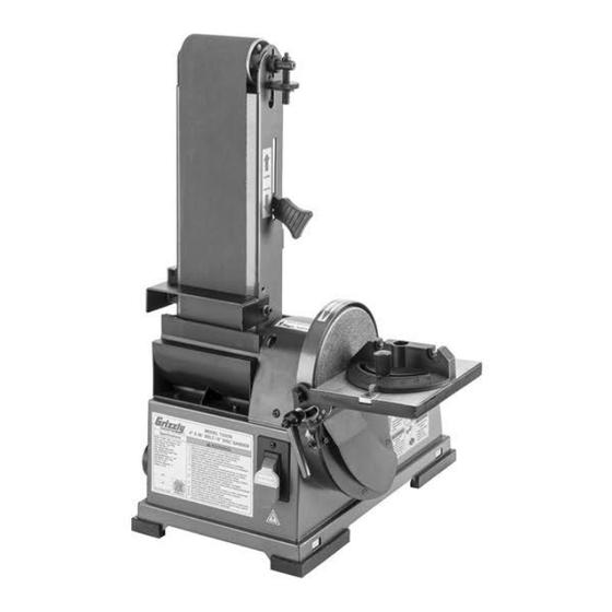
MODEL T33256
4" X 36" BELT / 6" DISC
COMBO SANDER
OWNER'S MANUAL
(For models manufactured since 04/22)
COPYRIGHT © APRIL, 2022 BY GRIZZLY INDUSTRIAL, INC.
WARNING: NO PORTION OF THIS MANUAL MAY BE REPRODUCED IN ANY SHAPE
OR FORM WITHOUT THE WRITTEN APPROVAL OF GRIZZLY INDUSTRIAL, INC.
#CS22256 PRINTED IN CHINA
V1.04.22
***Keep for Future Reference***
Advertisement
Table of Contents

Related Manuals for Grizzly T33256


Summary of Contents for Grizzly T33256
- Page 1 (For models manufactured since 04/22) COPYRIGHT © APRIL, 2022 BY GRIZZLY INDUSTRIAL, INC. WARNING: NO PORTION OF THIS MANUAL MAY BE REPRODUCED IN ANY SHAPE OR FORM WITHOUT THE WRITTEN APPROVAL OF GRIZZLY INDUSTRIAL, INC. #CS22256 PRINTED IN CHINA V1.04.22...
- Page 2 This manual provides critical safety instructions on the proper setup, operation, maintenance, and service of this machine/tool. Save this document, refer to it often, and use it to instruct other operators. Failure to read, understand and follow the instructions in this manual may result in fire or serious personal injury—including amputation, electrocution, or death.
-
Page 3: Table Of Contents
Table of Contents INTRODUCTION ..........2 SECTION 6: MAINTENANCE ......33 Contact Info............ 2 Schedule ............33 Manual Accuracy ........... 2 Cleaning & Protecting ........33 Identification ........... 3 Cleaning Sanding Belt/Disc ......33 Controls & Components ......... 4 SECTION 7: SERVICE ........34 Machine Data Sheet ........ -
Page 4: Introduction
ID label (see below). This information is required for us to provide proper tech support, and it helps us determine if updated documentation is available for your machine. Manufacture Date Serial Number Model T33256 (Mfd. Since 04/22) -
Page 5: Identification
Wear eye and ear protection. b) Support workpiece with miter gauge, backstop, or work table. c) Maintain ⁄ in. maximum clearance between table and sanding belt or disc. d) Avoid kickback by sanding in accordance with directional arrows. Model T33256 (Mfd. Since 04/22) -
Page 6: Controls & Components
Figure 3. ON/OFF switch. with sanding belt when platen is in vertical position. ON/OFF Switch w/Removable Key: Turns D. Table Lock Handle: Loosens to adjust table motor ON/OFF and prevents accidental tilt; tightens to secure. startup. Model T33256 (Mfd. Since 04/22) -
Page 7: Machine Data Sheet
MACHINE DATA SHEET Customer Service #: (570) 546-9663 · To Order Call: (800) 523-4777 · Fax #: (800) 438-5901 MODEL T33256 4" X 36" BELT / 6" DISC COMBO SANDER Product Dimensions: Weight................................33 lbs. Width (side-to-side) x Depth (front-to-back) x Height..............20 x 16-1/2 x 25 in. - Page 8 The information contained herein is deemed accurate as of 4/25/2022 and represents our most recent product specifications. Model T33256 PAGE 2 OF 2 Due to our ongoing improvement efforts, this information may not accurately describe items previously purchased. Model T33256 (Mfd. Since 04/22)
-
Page 9: Section 1: Safety
Never operate under the influence of drugs or injury or blindness from flying particles. Everyday alcohol, when tired, or when distracted. eyeglasses are NOT approved safety glasses. Model T33256 (Mfd. Since 04/22) - Page 10 Make sure they are properly installed, you experience difficulties performing the intend- undamaged, and working correctly BEFORE ed operation, stop using the machine! Contact our operating machine. Technical Support at (570) 546-9663. Model T33256 (Mfd. Since 04/22)
-
Page 11: Additional Safety For Combo Sanders
To avoid these hazards, keep all control when sanding force is applied. guards in place and closed. DO NOT wear loose clothing, gloves, or jewelry, and tie back long hair. Model T33256 (Mfd. Since 04/22) -
Page 12: Section 2: Power Supply
-10- Model T33256 (Mfd. Since 04/22) - Page 13 Two-prong outlets do not meet the grounding requirements for this machine. Do not modify or use an adapter on the plug provided—if it will not fit the outlet, have a qualified electrician install the proper outlet with a verified ground. -11- Model T33256 (Mfd. Since 04/22)
-
Page 14: Section 3: Setup
IMPORTANT: Save all packaging materials until you are completely satisfied with the machine and No list of safety guidelines can be com- have resolved any issues between Grizzly or the plete. Every shop environment is different. shipping agent. You MUST have the original pack- Always consider safety first, as it applies aging to file a freight claim. -
Page 15: Inventory
H. Table Stud ..........1 Wing Knobs M5-.8 x 14 ......2 Mounting Brackets ........4 K. Cap Screws M6-1 x 16 ....... 2 L. Flat Washers 6mm ........3 Figure 5. Inventory. M. Lock Washers 6mm........2 -13- Model T33256 (Mfd. Since 04/22) -
Page 16: Site Considerations
Figure 6. Minimum working clearances. Children and visitors may be seriously injured if unsuper- vised around this machine. Lock entrances to the shop or disable start switch or power connection to prevent unsupervised use. -14- Model T33256 (Mfd. Since 04/22) -
Page 17: Assembly
(see Figure 11), working from center outward, making sure it contacts surface evenly. Workbench Figure 9. "Direct Mount" setup. Sanding Disc (Aluminum Disc Hidden) Figure 11. Sanding disc stuck to aluminum disc. -15- Model T33256 (Mfd. Since 04/22) -
Page 18: Dust Collection
Tug hose to make sure it does not come off. To reduce risk of fingers or workpiece getting trapped between work stop and Note: A tight fit is necessary for proper sanding belt, adjust work stop within ⁄ " of performance. sanding belt. -16- Model T33256 (Mfd. Since 04/22) -
Page 19: Test Run
To prevent that from tect yourself from getting caught in moving happening, you must adjust belt tracking belt and disc when you start machine. before proceeding to next step. Refer to Checking/Adjusting Belt Tracking on Page 26. -17- Model T33256 (Mfd. Since 04/22) - Page 20 Switch disabling feature is not machine OFF and disconnect power. working correctly. This safety feature must Contact technical support. work properly before proceeding with reg- ular operations. Call Tech Support for Turn machine OFF. help. -18- Model T33256 (Mfd. Since 04/22)
-
Page 21: Section 4: Operations
Regardless of the content in this sec- in this manual are easier to understand. tion, Grizzly Industrial will not be held liable for accidents caused by lack of training. Due to the generic nature of this overview, it is not intended to be an instructional guide. -
Page 22: Sanding Tips
Choosing Sandpaper • Extend the life of the sandpaper by regularly The Model T33256 uses a 4" x 36" sanding belt using PRO-STIK® abrasive belt cleaners and a 6" sanding disc. Below is a chart that groups (see Accessories on Page 30). -
Page 23: Workpiece Inspection
Workpiece Adjusting Table Tilt Inspection The angle of the table on the Model T33256 can be adjusted between 0°–45° to sand angled Some workpieces are not safe to sand or may workpieces against either the sanding disc or the require modification before they are safe to sand. -
Page 24: Adjusting Miter Gauge
Adjusting Adjusting Platen Tilt Miter Gauge The Model T33256 platen can be positioned from 0°–90°, depending on your operation (see The miter gauge angle can be adjusted 60° to Figure 21). the right or the left, keeping angled workpieces accurate. -
Page 25: Changing Sanding Disc
Remove (4) button head cap screws shown in Figure 24 to remove disc cover. Sanding Disc The T33256 accepts 6" diameter PSA (pressure- sensitive adhesive) sanding discs. Use the fol- lowing steps to change the sanding disc when a sanding disc wears out or your operation requires a different grit size. -
Page 26: Disc Sanding
Figure 28. Bevel sanding. With light pressure, slowly move workpiece into left side of sanding disc. See Figures 26–29 for examples of disc sanding. Figure 29. Sanding round workpiece. Figure 26. 90° disc sanding. -24- Model T33256 (Mfd. Since 04/22) -
Page 27: Changing Sanding Belt
(1 of 2) Some sanding belts are designed to sand in only one direction and will have a direction indicated on the back of the belt. The Model T33256 is Sanding designed so that the sanding belt travels clock- Belt wise when viewed from the left side. -
Page 28: Checking/Adjusting Belt Tracking
— If sanding belt stays in center of rollers as you rotate belt by hand, proceed to Step 5. — If sanding belt does not stay in center of rollers as you rotate belt by hand, proceed to Step 4. -26- Model T33256 (Mfd. Since 04/22) -
Page 29: Platen Sanding
The allow motor to reach full speed. table also provides support for miter and bevel sanding. Items Needed Hex Wrench 5mm ..........1 Table Stud ............1 Open-End Wrench 14mm ........1 -27- Model T33256 (Mfd. Since 04/22) - Page 30 Adjust angle of table (and miter gauge, if desired) for operation. Connect machine to power, turn it ON, and allow it to reach full speed. Place workpiece on table (and against miter gauge, if used). -28- Model T33256 (Mfd. Since 04/22)
-
Page 31: Contour Sanding
Figure 43. End grain sanding. and continue moving workpiece profile along contour until you achieve desired shape, as shown in Figure 46. Figure 44. Miter sanding. Figure 46. Example of contour sanding. Figure 45. Sanding round workpiece. -29- Model T33256 (Mfd. Since 04/22) -
Page 32: Section 5: Accessories
Refer to our website or latest catalog for additional recommended accessories. Grizzly 6" Sanding Discs These tough, aluminum oxide sanding discs come in a variety of grits to fit the Model T33256. These sanding discs are pre-applied with top- quality pressure-sensitive adhesive. D1307—60-Grit, 3-Pk. - Page 33 Measures 3' wide x 5' long x ⁄ " thick. Figure 52. T10456 Anti-Fatigue Mat 3' x 5'. Figure 50. G0862 3 HP Portable Cyclone Dust Collector. www.grizzly.com 1-800-523-4777 order online at or call -31- Model T33256 (Mfd. Since 04/22)
- Page 34 T20456—DAKURA Safety Glasses, Black/Clear T28175—R3 SAFETY Stealth Safety Glasses T20502 T28175 T20503 T20451 T20456 Figure 54. T32736 Understanding Wood Finishing Book. Figure 56. Assortment of basic eye protection. www.grizzly.com 1-800-523-4777 order online at or call -32- Model T33256 (Mfd. Since 04/22)
-
Page 35: Section 6: Maintenance
To reduce risk of shock or accidental startup, always disconnect machine from power before adjustments, Cleaning the Model T33256 is relatively easy. maintenance, or service. Vacuum excess sawdust, and wipe off the remain- ing dust with a dry cloth. If any resin has built up, use a resin dissolving cleaner to remove it. -
Page 36: Section 7: Service
3. Belt is stretched unevenly, worn, or damaged. 3. Replace belt (Page 25). excessively. 4. Idler/drive roller is loose. 4. Tighten idler/drive roller. 5. Weak or broken tension spring. 5. Replace spring. -34- Model T33256 (Mfd. Since 04/22) - Page 37 90°. 1. Calibrate miter gauge scale (Page 38). Workpiece not 1. Miter gauge body is not square to miter bar. sanded square when miter gauge is set to 90°. -35- Model T33256 (Mfd. Since 04/22)
-
Page 38: Checking/Replacing V-Belt
Belt is correctly tensioned when there is approximately ⁄ " Figure 59. Location of machine base cover and deflection when it is pushed with moderate Phillips head screws. pressure, as shown in Figure 58. -36- Model T33256 (Mfd. Since 04/22) - Page 39 " deflection, then tighten cap screws from Step 6. 15. Install machine base cover, then turn machine upright. 16. Secure belt cover with screw removed in Figure 61. Location of table fasteners. Step 2. -37- Model T33256 (Mfd. Since 04/22)
-
Page 40: Calibrating Miter Gauge Scale
90°, pro- ceed to Step 3. Loosen Phillips head screw shown in Figure 64, adjust indicator to point to 90°, Table Lock then tighten screw. Handle Figure 66. Squaring table to sanding belt. -38- Model T33256 (Mfd. Since 04/22) - Page 41 Loosen angle indicator Phillips head screw (see Figure 67), adjust indicator to zero, then tighten screw. Figure 68. Location of side cover. Angle Indicator Figure 67. Location of angle indicator and Phillips head screw (disc table indicator shown). -39- Model T33256 (Mfd. Since 04/22)
-
Page 42: Section 8: Wiring
Technical Support at (570) 546-9663. The photos and diagrams included in this section are best viewed in color. You can view these pages in color at www.grizzly.com. -40- Model T33256 (Mfd. Since 04/22) -
Page 43: Wiring Diagram
DKLD AN17 20A 125V 120V MOTOR Ground Capacitor Ground Ground 30µF 250VAC Neutral 120 VAC Ground 5-15 Plug Figure 69. ON/OFF switch wiring. Figure 70. Run capacitor wiring. READ ELECTRICAL SAFETY -41- Model T33256 (Mfd. Since 04/22) ON PAGE 40! -
Page 44: Section 9: Parts
SECTION 9: PARTS We do our best to stock replacement parts when possible, but we cannot guarantee that all parts shown are available for purchase. Call (800) 523-4777 or visit www.grizzly.com/parts to check for availability. Main 44 45 46 54 57... - Page 45 WRENCH 14MM OPEN-END PT33256068 BEARING COVER PT33256113 CABLE TIE PT33256069 CAP SCREW M5-.8 X 10 PT33256114 MOUNTING BRACKET PT33256070 WORK STOP BUY PARTS ONLINE AT GRIZZLY.COM! -43- Model T33256 (Mfd. Since 04/22) Scan QR code to visit our Parts Store.
-
Page 46: Labels & Cosmetics
Safety labels help reduce the risk of serious injury caused by machine hazards. If any label comes off or becomes unreadable, the owner of this machine MUST replace it in the original location before resuming operations. For replacements, contact (800) 523-4777 or www.grizzly.com. BUY PARTS ONLINE AT GRIZZLY.COM! -44- Model T33256 (Mfd. -
Page 47: Warranty & Returns
WARRANTY & RETURNS Grizzly Industrial, Inc. warrants every product it sells for a period of 1 year to the original purchaser from the date of purchase. This warranty does not apply to defects due directly or indirectly to misuse, abuse, negligence, accidents, repairs or alterations or lack of maintenance.
Need help?
Do you have a question about the T33256 and is the answer not in the manual?
Questions and answers