Table of Contents
Advertisement
Advertisement
Table of Contents

Related Manuals for Seaga Naturals2GO NTG4000


Summary of Contents for Seaga Naturals2GO NTG4000
- Page 1 Owner’s Manual Vending System Model NTG4000 Revision 1.4, October 2013 ...
-
Page 2: Introduction
EQUIPMENT INSPECTION After you have received your vendor and have it out of the box, place it on a secure surface for further inspection. Note: Any damages that may have occurred during shipping must be reported to the delivery carrier immediately. Reporting damages and the seeking of restitution is the responsibility of the equipment owner. The factory is willing to assist you in this process in any way possible. Feel free to contact Seaga’s Customer Care Department with questions you may have on this process. It is important that you keep the original packaging for your vending machine at least through the warranty period. If your machine needs to be returned for repair, you may have to purchase this packaging if it is not retained. Once you have your vendor located, we suggest that you keep this manual for future reference, or you can view this manual online at seagamfg.com. Should any problems occur, refer to the ... -
Page 3: Table Of Contents
INTRODUCTION ...........................2 Preliminary Information ......................4 Initial Setup ..........................7 Equipment Setup ........................8 Customer Interface ........................20 Setting Up and Loading the Payment Systems ................22 Coin Changer ..........................22 Loading Changer ........................22 Coin Retrieval ..........................22 Clearing Coin Jams ........................23 Removal of Coin Changer ......................25 BILL VALIDATOR ........................25 Bill Validator Capacity .......................25 Bill Retrieval ..........................25 REMOVING BILL VALIDATOR .....................26 Clearing Bill Jams ... -
Page 4: Preliminary Information
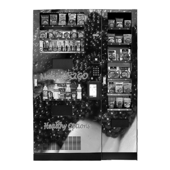
Preliminary Information Figure 1 – The NTG4000 Vending System Main Unit – Snack, Beverage, Controls Entree Unit Entree Display Snack Window Display Display Window Bill Validator Snack Delivery Door Keypad Coin Return Button Coin Slot Main Door Handle and Lock Beverage Entree Door Display Handle and Lock Window Air Vend Beverage Delivery Door Coin Return Entree Delivery Door Door Refrigeration Vents ... - Page 5 Figure 2 ‐ Interior of machine and controls Display VMC Bill Validator Beverage Harness Coin Changer Vertical Drop Door Hasps 1.4 10.13 Page 5 ...
- Page 6 Power Requirements Your NTG4000 system is equipped with a GFCI cord and grounded plug. The wall receptacle used must be properly polarized, grounded and of the correct voltage. Operating the NTG4000 system from a source of low voltage will VOID YOUR WARRANTY. Each NTG4000 system should have its own 12 Amp electrical circuit that is protected by a circuit breaker or fuse conforming to local power safety regulations. Unpacking the Vending System Remove all packing materials from the interior of the merchandiser. Keep all documents found packed inside which include payment system and accessory manuals as appropriate. Keep and set aside any accessory kits. Controls and Indicators Display The Display is how the vending system communicates with your customers while they are in front of the machine. The customer may see messages about how much an item costs, when a ...
-
Page 7: Initial Setup
Initial Setup Moving the Vending System Your NTG4000 system should never be moved with product or coins loaded and should be completely empty and any moving parts secured. The system can be located flush to the back wall but you will want at least 6” clearance on either side for the doors to open properly while you service the machine. After locating your vending system, plug the two power cords in and turn the system on. ... -
Page 8: Equipment Setup
Figure 4 – Wire Harnesses Two (2) connections Entree Unit to back of Wire Harness main unit Equipment Setup Loading Snack Trays Each snack tray has a release lever located on the right side. To place the tray in load position, press down on the release lever and slide the tray forward (toward you) until the roller hits the stop built into the slide rail. Gently release the front of the snack tray until it is tilted down and all coils are exposed (Figure 5). Figure 5 – Snack Tray in Load Position Each tray has a Release Lever Tray in Load Position 1.4 10.13 Page 8 ... - Page 9 Products Make sure your products are appropriate for the column and coil you are placing them in. Do not force products that are too wide into a narrow tray or too tight coil as this will cause vend problems for your customers. The product must also pass under the tray immediately above the one you are loading and should not touch products on either side. Once you have the appropriately sized products for each selection, correct loading of the products should be between the coils and resting on the product tray itself. See Figures 6 and 6a below: Figure 6 – Load products properly and neatly Correct Incorrect Incorrect ...
- Page 10 Removing Snack Trays It is sometimes necessary to replace a snack tray or you may find it easier to work on certain elements of a tray if it is removed from the vending system cabinet. To remove a snack tray: 1.) Remove all product from the tray you want to remove. 2.) Reach in and unplug the proper tray harness as shown in figure 7. Figure 7 – Tray Harnesses Tray 100 Harness Tray 200 Harness Tray 300 Harness 3.) Rest the tray harness on top of the tray you are removing to keep it out of the way. 4.) Press the release lever on the right side of the tray and slide the tray forward (toward you) until you feel the roller come to the built in rail stop. 5.) With a firm hold on the tray, lift up to release the roller from the rails on the sides of the cabinet. 6.) Pull the tray free and place it on a sturdy, flat surface to complete your work. 1.4 10.13 Page 10 ...
- Page 11 Figure 8 – Remove the tray Tray 300 Harness Lift tray free Adjusting Coils If you are required by a location to vend a product of a non‐standard size, you may need to order a different coil and install it. Replacing a coil is easier with the tray removed, as described in the last section. To replace a coil: 1.) Remove the coil from the coil driver by lifting the back of the coil up off the coil driver. You will need to move the bottom of the coil clear of the coil driver to completely remove the coil. See Figure 9 ...
- Page 12 Figure 9 – Removing and Aligning a Coil Lift Coil Coil Driver with three (3) adjustment options Apply pressure to the straight part of the coil that is inserted into the Coil Driver. Lift up the Coil to remove. Back of Product Tray, Snack or Entree If you are experiencing vending issues with certain products, you may need to adjust the coil rotation to better provide the momentum to push the snack off the tray and into the delivery area. To adjust the coil rotation: 1.) Squeeze ...
- Page 13 Replacing Snack Motors As one of the moving parts of the vending system, vend motors experience regular wear and may need to be replaced on occasion. To replace a vend motor, remove the tray as described earlier and then remove the coil driver and coil as shown in Figure 11. 1.) Press the tab unscrew two screws as shown in Figure 11. 2.) Unplug motor harness. Figure 11 –Motor on Snack Tray Unplug motor harness Unplug motor harness 3.) Replace motor and plug motor harness back in. 4.) Perform at least 5 (five) test vends to insure a proper vend. Loading Beverage Lanes The NTG4000 vending system uses vertical drop columns to provide the most flexibility in a compact space. The Vertical Drop Columns in your machine use an Auger that rotates counter‐...
- Page 14 Vertical Product Columns – Load products horizontally (laying down) 1.) For bottles, place top of the first bottle against the front of the column, making sure the Sold Out Switch is depressed. Place the second bottle to the rear of the column, facing the bottom of the bottle with the bottom of the first bottle. Load 12 oz. cans bottom to bottom in the first two positions, then top to top in the back position. Load 16 oz. cans bottom to top. 2.) To adjust the rear spacer, grasp firmly and lift, freeing the spacer from the slots in the column sides. Move the rear spacer to the closest slot to the back of the bottle or can placed in the rear of the column. The gap between the rear spacer and the rear bottle or can must be less than ½ inch. The slots are in ½ inch increments to let you adjust for many sizes of products. Lower the rear spacer into the new position, making sure the spacer is straight vertically. ...
- Page 15 Adjusting Beverage Lanes The shim positions are adjustable in each column. By making adjustments to the shim, back gate and cams, you can covert bottle lanes to cans and vice versa as well as accommodate most packing. Factory settings for the shims are shown below: Figure 13 ‐ Shims Shim position – 12 oz. cans Side Wall Thumb screw Adjustable Shim Shim position – 16.9 oz bottles and cans, 20 oz bottles Adjustment Bar To adjust the shim, loosen the thumb screw ONLY SLIGHTLY and slide the adjustment bar to the correct position. Tighten the thumb screw. Oddly shaped product may take some testing, trial and error to determine the correct adjustment. ...
- Page 16 Figure 14 – Rear Spacer Adjustment Thumb Screw Holes Position rear spacer within ½ inch or less of the loaded product and tighten thumb screw in nearest hole 1.4 10.13 Page 16 ...
- Page 17 Each vertical drop column is factory set for a specific product size and type when you receive your machine. This size and type is noted on a label located in front of each vertical drop column as shown in Figure 15: Figure 15 – Vertical Drop Column Labels Label Max Product Size Type Capacit Loading Instructions y Coca‐Cola and varieties 16.9 oz/500 ml Bottle 14 Load bottom to bottom Nestle Chocolate Milk 14 oz/414 ml Bottle 14 Load bottom to bottom Pepsi, Diet Pepsi, Mt. Dew and 16.9 oz/500 ml Bottle 14 Load bottom to bottom varieties 7 up and Diet 7up 16.9 oz/500 ml Bottle 14 Load bottom to bottom Dr. Pepper, Diet and varieties 16.9 oz/500 ml Bottle 14 ...
- Page 18 Home Switch Adjustment Due to variance in product sizes, it may be necessary to adjust the position of the Home Switch. This can be accomplished by rotating the Home Switch Mounting Ring clockwise or counter‐ clockwise to adjust the stop position of the Auger. Figure 16 ‐ Front of vertical drop system; motors removed from two selections Home Switches Sold Out Switches Can Cam Bottle Cam Home Switch Mounting Rings To make adjustments: 1.) Determine if you are adjusting a Bottle Column or Can Column by looking at the Cams or Column Labels. 2.) With the column empty, test vend the selection to rotate the Auger until the opening faces the 3:00 o’clock position. This is the beginning of the vend cycle. 3.) Load a single row of drinks on top of the Auger, laid down and oriented as shown in the ...
- Page 19 5.) If two products drop on the first vend in Step 4, the Auger turned too far. Adjust the Home Switch Mounting Ring slightly clockwise. Note: Make only 1/8” adjustments. 6.) Go back to Step 2, noting that one and only one product should drop. If this is a 12 oz. can column, test three times to insure that all three products drop correctly. 7.) Fill the column to the top and run a full cycle one more time, as the weight of a full column ...
-
Page 20: Customer Interface
Loading Beverage Live Display Unlike the snack section of the vending system, the products that will vend are not viewable by your customers when they are positioned in the vertical drop columns. To provide a live display, a product display shelf has been provided. Take care to use packaging that is in perfect condition and products that are still within their expiration date to present the best possible retail store front to your potential customers. To load the live product display: 1.) Remove the Drink Display Back Panel by loosening and removing the thumb screws located on either side of the panel. ... - Page 21 the vendor and the cost of their selection among other information as programmed. The display also shows the operator the Service Mode functions for setting the the vendor. Fig. 20a – LCD Display in Sales Mode When in Sales Mode Display Formats Top Line of Display Reads Normal Operation, no credit available $00.00 Normal Operation, some credit available $00.01 – 99.99 After Pressing a selection, if there is no credit, or the credit is less than the selection’s price, the price of the selection is displayed for a few seconds before reverting to one of the above credit display formats. (If a coin or other payment is made the display Price $00.01 – 99.99 reverts immediately to display the credit available) ...
-
Page 22: Setting Up And Loading The Payment Systems
Date and Time are always displayed on the second line in Sales Mode. If a calorie value is set for a selection, the value will be displayed when the product is vended or when a selection is made without any credit. Setting Up and Loading the Payment Systems Coin Changer The Coin Changer receives and returns change to customers. The Coin Changer will accept Quarters, Dimes, and Nickels. Once the coin tubes reach the required inventory level, all other coins will be routed into the coin overflow tray. Loading Changer As change is given to the customer in coins only, it is recommended that you initially load the coin hoppers half full when setting up your machine and that you do not allow your machine’s coin inventory to drop below this level. In order for your VMC to keep an accurate coin inventory, enter MENUS Mode, scroll through to Settings, Coin Refill, and load coins in through ... -
Page 23: Clearing Coin Jams
Figure 20 ‐ Coin Changer Coin Return Lever Coin Funnel Diagnostic LED User Interface Buttons Coin Channel Acceptor Gate Assembly Cover Cassette Latch Coin Cassette Clearing Coin Jams 1. Unplug the machine from the power source 2. Unlock and open the Front Door 3. Open the Acceptor Gate Assembly by pulling forward on the Coin Funnel 1.4 10.13 Page 23 ... - Page 24 4. Check for coin jams in this area. Note: the ramp in this area should also be cleaned on a regular basis to insure trouble‐free operation. Coin Ramp – keep clean 5. Open the Coin Channel Cover by using the tab on the left side to pull forward 6. Check this area for any jammed coins 1.4 10.13 Page 24 ...
-
Page 25: Removal Of Coin Changer
Removal of Coin Changer To Remove the Coin Changer: a. Disconnect the power to the machine b. Disconnect the Wire Harness to the changer c. Open the Acceptor Assembly as shown previously d. Loosen the three (3) Mounting Screws e. Lift Changer and remove. BILL VALIDATOR The Bill Validator allows your customers to pay for their purchase with paper currency. Your Bill Validator is installed at the factory, and is set to validate $1 and $5 bills, but will not accept bills if the coin tubes are empty. The Bill Validator verifies, accepts and stores paper currency but change is given in coins only. Bill Validator Capacity The Bill Storage Box will hold approximately 250 bills. Bill Retrieval The bills your customers spend are kept in the Bill Storage Box. 1. To Retrieve Bills. a. Unlock and open the Service Door b. Open door located on top of bill collection box and lift out bills c. Close top door on bill collection box after bills are retrieved ... -
Page 26: Removing Bill Validator
Figure 21 – Bill Validator Tab Bill Storage Box (4) Mounting Nuts Lower Housing REMOVING BILL VALIDATOR From time to time it may be necessary to remove the Bill Validator for cleaning and clearing jams. 1. To remove the Bill Validator a. Unplug the machine from the power source b. Unlock and open the Front Door c. Push Bill Validator Tab forward and slide Bill Storage Box up to remove Tab d. Disconnect Bill Validator from Wire Harness e. Remove the Four (4) Mounting Nuts. 1.4 10.13 Page 26 ... -
Page 27: Clearing Bill Jams
Wire Harness Four (4) Mounting Nuts f. Remove Bill Validator Clearing Bill Jams It is possible that a torn or damaged bill can jam within the Bill Validator, putting it out of service. 1. To Clear a Jam. a. Remove Bill Storage Box as instructed above b. Remove bill jam, and reassemble 1.4 10.13 Page 27 ... -
Page 28: Programming
Programming Service mode is used to program your NTG4000 vending system. To enter service mode, Unlock and open the front door to access the VMC, and press the MENUS Button. (Fig. 2 and Fig. 23) Figure 23 – VMC and MENUS Button MENUS Button Figure 24 – Display in Service Mode; first sub‐menu is Audit 1.4 10.13 Page 28 ... -
Page 29: Service Mode
SERVICE MODE Selections are Numeric and on decals on each tray front as well as part of the live beverage display. For example: Numeric (always three key presses) Top tray 1‐0‐1 First column Third tray 3‐0‐5 Fifth (5 ) column Fourth tray 4‐1‐0 Tenth (10 ) column Service Mode The operation of the machine can be adjusted by entering service mode by pressing the MENUS button on the VMC circuit board and then accessing the appropriate operation. Price setting, audit display and operating modes can be read and adjusted from here. The user can ... - Page 30 Operation 1.) Enter Service Mode by pressing the MENUS Button on the VMC Circuit board. 2.) Each Service Code can then be accessed using the 9 (Next) and 0 or 0(Previous) buttons to scroll through the menus in sequence: 1. AUDIT Displays Audit ‐‐ 2. PRICE SETTING Displays Prices ‐‐ 3. TEST MODE Displays Test Mode‐‐ Displays Control Mode: ** 4. CONTROL SETTING Where ** is the current value 5. SOUND On/Off Displays Sound : * Where * is the current state (Off or On) Displays Display Errors 6. DISPLAY ERRORS Displays Clear Errors 7. CLEAR ERRORS Displays Set Clock 8. SET CLOCK Displays Payment Dev: n 9. MDB PAYMENT DEVICES ...
-
Page 31: Price Setting
Audit Within Service Code Audit readings can be taken from the Display with regards to cash taken, and number of products vended. The following details can be obtained on the Display. 1. Total Cash IN : CA305 (up to 999999.99) 2. Total Product Sales Value: VA101 (up to 999999.99) 3. Total Count of Free Vend Tokens : TA202 (up to 49999) 4. Total Coins IN : CA306+CA307 (up to 999999.99) 5. Total Cash Out : CA403 (up to 999999.99) # 6. Total Bills IN : CA310 (up to 999999.99) 7. Total Card Payment : DA201 (up to 999999.99) 8. Total Manual Dispensed amount: CA404 (up to 999999.99) Selection (alpha then numeric, or * then 3 digits) Display the total number of individual vends of that selection (up to 49999) Press the Scroll buttons (9 or 0) repeatedly until the LCD Displays Audit. You are now in Audit Mode Press Selection 1 to reveal the total cash ($/£/€) and (c/p) taken. Displays 1: ****. ** Press Selection 2 to reveal the total sales value Displays 2: ****. ** Note: Decimal values “roll‐over” from 999999.99 to 0.00 ... - Page 32 CONTROL SETTING 1. Press the Scroll buttons (9 or 0) until the LCD Displays Control Mode : ** (where ** is current value) You are now in Control Word Setting 2. Press Selection Button 1 to 8 to change the control word Displays Control Mode : ** The control word options supported are : Code Multivend Forced Vend Positive Vend Sensor 1 No – single vend No Off 2 Yes ‐ multivend No Off 3 No – single vend Yes Off 4 Yes ‐ multivend Yes Off 5 No – single vend No On 6 Yes ‐ multivend No On ...
- Page 33 DISPLAY ERRORS 1. Press the scroll buttons (9 or 0) until the display reads D isplay Errors In this mode, press any selection button (other than 9 or 0) to display error codes in sequence, shown in plain text (see table of error messages) CLEAR ERRORS 1. Press the scroll buttons (9 or 0) until the display reads Clear Errors In this mode, press any selection button (other than 9 or 0) to clear all errors – confirmed with a “Cleared” display. SET CLOCK 1. Press the scroll buttons (9 or 0) until the display reads Set Clock In this mode, press the selection buttons listed below to set the current time, date and day of week: 1. Time – displayed in a 24 hour clock format as Time : HH:MM Press 4 digits in turn to set the time. 2. Date – displayed as Date D/M: DD/MM/YY Press 6 digits in turn to set the date, month and year. Alternate display displayed as Date M/D: MM/DD/YY Press 6 digits in turn to set the date, month and year. 3. Day of Week – displayed as Sunday .. Saturday enter a single digit to set the day of week (1 = Sunday, 2 = Monday … 7=Saturday) ...
- Page 34 MOTOR HOME and COUNT 1. Press the scroll buttons (9 or 0) repeatedly until the display reads Home & Count In this mode, press and key other than 9 or 0 to home and count the Motors. The display will show the row/column being homed. If the selection is OK the count of motors so far is shown, otherwise “Error” is displayed for faulty or non‐existent selections. MDB PAYMENT DEVICES 1. Press the scroll buttons (9 or 0) repeatedly until the display reads P ayment Dev: ** (where ** is current value) You are now in Payment Device Setting 2. Press a numeric selection (1 – 7) to change the value Payment Dev: ** The payment device values supported are: Value MDB Coin MDB Bill Reader MDB Card Reader Changegiver 1 ON OFF OFF 2 OFF ON OFF 3 ON ON OFF ...
- Page 35 TEMPERATURE SETTINGS 1. Press the scroll buttons (9 or 0) repeatedly until the display reads T emp Set ** This menu option allows the zone temperature settings to me displayed and modified. ** shows the current state. On/Off for the zone control an C or F for the temperature scale in use: F means Fahrenheit, C means Celsius Examples: Temp Set On F Zone control is ON, temperatures in Fahrenheit Temp Set On C Zone control is ON, temperatures in Celsius Temp Set Off F Zone control is OFF, temperatures in Fahrenheit In this mode, press the selection buttons listed below to set mode and temperature limits 1.) Turn the Zone ON 2.) Turn the Zone OFF 3.) Temperature Setting ‐ Press 2 digits in turn to set the temperature (00 – 99). If a negative temperature is required press the A selection button first. Any other alpha ...
- Page 36 INSTALLER MODE This mode can be set to allow a user to go through a pre‐determined reminder sequence when installing a machine on site. INSTALL MODE <1> default display shows the machine is install mode at stage 1. “9” to continue – goes to stage 2 if a coin changer is enabled otherwise goes to stage 3 “10” to skip – goes to stage 3, warns if any coin tube empty COIN FILL <2> stage 2 – allows tubes to be filled “9” or “0” to continue – goes to stage 4, warns if any coin tube empty MOTOR TEST <3> stage 3 – allows motors to be tested “9” to action “home each motor with 1 turn minimum” then goes to stage 4 “10” to skip – goes to stage 4 without any action SHOW ERRORS <4> stage 4 – error display – automatically skips to stage 6 if there are no errors after a “NO ERRORS” display for 2 seconds “9” to action – scrolls through errors then goes to stage 5 “0” to skip – goes to stage 6 without any action CLEAR ERRORS <5> stage 5 – clear errors “9” to action – clears errors then goes to stage 6 “0” to skip – goes to stage 6 without clearing the errors SET PRICES <6> stage 6 – allows prices to be set – identical to Price Setting Menu. This allows single selection pricing, whole tray or whole machine. ...
-
Page 37: Calorie Setting
CALORIE SETTING Enter calorie information by using Service Code Calories. 1.) Press the Scroll buttons (9 or 0) repeatedly until the LCD Displays Calories You are now in Calorie Value Setting Mode 2.) Make a selection to display the current calorie value Displays the row and column and then nnnnn 3.) Enter 5 digits. The display will then revert to Calories when this is complete. 1.4 10.13 Page 37 ... - Page 38 ERROR MESSAGES Error message Fault detected Hard/Soft Action Fault Motor Err Motor 101 .. 610 Soft Repair/replace motor or home 101..610 respectively switch Numeric selections Temp Sensor Err Temperature sensor error Soft Repair/replace temperature sensor or wiring Over Temp Compressor Temperature Hard Repair compressor sensor error (overtemperature) Comp Sensor Err Compressor Temperature Hard Repair/replace temperature sensor error sensor or wiring H & S (n) Health & Safety error Hard Check/replace products and 0 = timeout, 1= reset error by entering menus. temperature ...
-
Page 39: Refrigeration
Refrigeration Your beverages are kept cold by a high efficiency refrigeration system having two air circulation fans to chill the cans and bottles. The refrigeration unit can be easily accessed by opening the Front Door. Remove the blue thumb screws from the center of the refrigeration deck and unplug the three wire harnesses on the side of the deck (Fig. 25). The refrigeration deck can now be pulled out from the machine. Please make sure you unplug wire harnesses prior to pulling all the way out. ... - Page 40 This process is accomplished by the use of a sealed compressing system using an ozone friendly gas commonly known as R134a refrigerant. The system is comprised of several key mechanical components: the condenser, the evaporator and the compressor. The condenser is located in the lower front left of the machine and it is where the heat is dissipated from the cooling process and blown to the outside of the machine. The evaporator is located inside the machine towards the back of the cooling system underneath the beverage unit section being cooled. Its purpose is to absorb the heat from the drink selections and provide the cool air needed to refrigerate the beverages. The compressor is the heart of the cooling system and its purpose is ...
-
Page 41: Refrigeration Status Display
Refrigeration Status Display Press the “10” key on the Keypad when the machine is in Sales Mode to display the following indications of the refrigeration system activity on the LCD Display: Figure 26 – Refrigeration Indicators on LCD Display Current Temperature in Vertical Drop Beverage Area Character 2 Character 1 (blank) = Lights Off/Compressor Off (blank) = Normal Operation (Minus Sign ‐ ) = Lights On/Compressor Off (Minus Sign ‐ ) = Recent Defrost (Underscore _ ) = Lights On/Compressor On (Underscore _ ) = Compressor Off/Defrost Cycle (Dot • ) = Lights Off/Compressor On (Dot • ) = Compressor Off/Delay Mode on/Power Up ... -
Page 42: Troubleshooting
Troubleshooting NO DISPLAY ON THE FRONT PANEL Harness may be unplugged Faulty display harness Transformer fuse blown Restart machine Display board defective SELECTION WILL NOT VEND Disconnected tray wire harness Detection system may be blocked, if enabled Vend mechanism binding on tray Product jammed Tray or Motor connection unplugged or faulty connection Defective motor... - Page 43 My machine will not take in bills but accepts change ok. Several options here but the most common especially when first setting up the machine is that there is not enough change in the changer. By looking at the display it will give you a clue as to what may be wrong.
- Page 44 Freeport IL 61032 Seaga will repair or replace, at our option, any covered part which meets the provisions herein during the warranty period. It is our discretion to replace defective parts with comparable parts. Seaga reserves the right to make changes or improvements in its products without notice and without obligation, and without being required to make corresponding changes or improvements in equipment already manufactured or sold.
Need help?
Do you have a question about the Naturals2GO NTG4000 and is the answer not in the manual?
Questions and answers