
Related Manuals for Seaga SP 432


Summary of Contents for Seaga SP 432
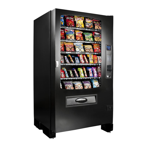
- Page 1 VÉÄÄxvà|ÉÇ Ambient and Refrigerated models SERVICE and PARTS MANUAL 700 Seaga Drive, Freeport, IL 61032, U.S.A. visit: seagamfg.com email: info@seagamfg.com Revision 2012.02.27...
- Page 2 8:30 a.m. - 4:00 p.m. CST. Mon thru Fri +44(0)1492 874010 815.297.9500 ext 160 +44(0)1492 874644 Fax 815.297.1758 Fax email: customercare@seagamfg.com email: info@seaga.co.uk Seaga UK Ltd. Seaga Manufacturing, Inc. Unit 8, Caebach, Off Builders Street 700 Seaga Drive Llandudno North Wales LL30 1DR Freeport, IL 61032 U.S.A. www.seaga.co.uk www.seagamfg.com...
- Page 3 Shipping Weight 470 lbs. 703 lbs. 698 lbs. 528 lbs. 764 lbs. 721 lbs. UK Version, 220 V 4 Wide 5 Wide Specifications SP 432 (F) SP 430D(F) SP 735R(F) SP 540(F) SP 536D(F) SP 536R(F) Ambient Refrigerated Refrigerated Ambient Refrigerated...
- Page 4 Finish Powder Coat paint Number of Trays 6 Standard ENVIRONMENT Location Environment: Indoors only ELECTRICAL REQUIREMENT US version requires one (1) 120 VAC 12 Amps grounded outlet. UK version requires one (1) 220 VAC 12 Amps grounded outlet. STANDARD COIL CONFIGURATION Subject to change without notice.
- Page 5 CAUTION: Certain procedures described in this manual require that voltage be on in the machine. Only trained personnel should perform these functions. Use extreme caution while performing the procedures marked with the voltage symbol shown here: CAUTION: Certain procedures described in this manual require a qualified, trained technician to perform the particular task at hand.
- Page 6 Proper leveling is also necessary to allow easy opening and closure of the vending machine door and to insure proper vending operation. Fig. 3 Leg Leveler Interior View Fig. 4 Control Board and Brown Service Mode Button Display Board Red Main Power Switch Refrigerated model, modular refrigeration unit.
- Page 7 Your vendor is intended for indoor use only. Your vendor must be set on a level, well-supported location. Always unload vendor before transporting it. Remove all wire ties and protective sheeting prior to vending. CAUTION! Procedures marked in this manual with the symbol shown to the left require power to the machine, which means that there is a shock hazard.
- Page 8 LOADING PRODUCTS To present your product in as an attractive and professional manner as possible, do not load any damaged items, and make sure items are facing forward for easy identification by your customer. Note: The size of the item being vended must be larger than the Helix Coil, but smaller than the Product Chute, to vend correctly.
- Page 9 LOADING BAGGED OR BOXED ITEMS When vending small bagged items in the 8 or 10 selection trays can be a problem when the products are not loaded properly. The flap edges of some products may get trapped under the spiral and cause the product to “hang up”. It is recommended that the bottom flap of this type of packaging be folded forward and up (Fig.
- Page 10 Installed Installed, side view. Installed, Front View Installed, Top View LOCK Your vendor has one Lock, more commonly known as T-handle lock. To unlock the front door, insert key and turn clockwise ¼ turn. When unlocked the ‘T’ of the Lock will pop out from its base. Turn the ‘T’ 15 to 20 times counter clock wise to unlock the door.
- Page 11 DISPLAY The VFD Display (Fig. 9) is a 2 x 20 Text Display. The display shows the customer the amount of money entered into the vendor and the cost of their selection among other information as programmed. It shows the operator the Service Mode functions for setting the various functions of the vendor.
- Page 12 To enter into service mode open the vendor door and Press the Brown Menu Service Mode Button (Fig. 10). After pressing the Service mode switch the controller will beep twice and the display will change to show “Service Menu” on the first line and “Prices”...
- Page 13 Exiting service mode The controller will remain in service mode as long as the user keeps using the keypad to move through the various service mode MENUS. The controller will automatically exit service mode and return to sales mode if any of the following occur: 1) The user is inactive for more than 3 minutes 2) The user presses the EXIT key (G).
- Page 14 In order to enter the price, Press the corresponding number. For example, if the Price of a Selection is $0.75, then Press “7” and “5”. Press F to accept the value; G to exit to the main menu. Note: Discount prices can only be set using a Seaga Smart Card.
- Page 15 Test the motors if they are home and total number of motors in the machine are displayed on the right 2. 2 Home Motors corner. (Fig. 6) Tests Individual Motors 2. 2 Motor 2.2.1 Enter Row/Column 2. 3 Positive Vend Sensor Test the vend sensor –...
- Page 16 3. 2 Change Out Displays Total Amount of Coins dispensed during transactions Displays Total Amount of Bills inserted during 3. 3 Bills In transactions Displays Total Amount of Card Transaction 3. 4 Card In 3. 5 Manual Dispense Displays total Amount that is dispensed manually during servicing of Coin Mechanism 3.
- Page 17 Shows the count of the coins of each denomination being inserted. Manual Dispense of the Coin mech is enabled in this menu option. Fig. 12 Depending on the model of changer installed, the amount will vary. ON/OFF ON/OFF 4.9.1 Coin Changegiver Enabled/Disabled 4.9.2 Bill Reader...
- Page 18 SECTION 4 SMARTWARE V.E The Seaga Smartware setup utility enables Setup smart cards to be used to set the configuration of the new generation of Seaga vending machine controller boards. The utility works in conjunction with a USB smart card reader.
- Page 19 Installing the Smartware Application Either : Insert the CD into the CD ROM drive Select the “Install Seaga Smartware” option Or : Run the programme "setup.exe" in the top level folder on the CD and follow the instructions.
- Page 20 General Operations Read Seaga Smart Card – read an existing smart card Write Seaga Smart Card – programme a card with the current settings Save to File – save the complete settings to a text file Load from File – restore previously saved configurations Check Website for Latest Version –...
- Page 21 CONFIGURATION PAGE (continued) Machine Selection / Basic Settings Use the Machine Type “pull-down” to select a standard machine configuration, or select a specific VMC type. Multivend, Forced Vend, Accept Tokens/Coupons and Sound ON – check the option to enable the corresponding feature.
- Page 22 PRICES PAGE Depending on the machine configuration, up to 80 Price Boxes will be displayed for the machine. To set a particular price type the value, in cents/pence, into the corresponding price box. To set ALL the prices to the same amount, enter the amount in the ALL Price box and click the Set All Prices button. The VMC can hold prices for the Main Machine and also up to three Satellite (MDB USD) machines –...
- Page 23 PRICES PAGE (continued) Discount Prices Select Discount Prices using the Price Bank pull-down. The VMC can operate at discounted prices between the Discount Start Time and Discount End Time points - refer to the “Timed Events” section. Revision 2012.02.27...
- Page 24 PRICES PAGE (continued) Meal Deals These are multiple selections that may be offered at a discount price for the group of selections. Meal deals are selected using the special selection prefix “GG” followed by the 1 – 10 key. The Meal Deal price is charged to the customer and multiple products are vended as specified.
- Page 25 INTERNATIONAL PAGE Language Select the default language for the display using the pull-down list. One language option is EEPROM. This language bank may be edited for special configurations and non-supported languages. Refer to the Text Messages page for more details. Currency Display Choose the desired currency Symbol and the number of Decimal Places to be displayed.
- Page 26 PAYMENT PAGE Payment Devices Check the corresponding boxes to turn Card, Coin and Bill payment on Executive – check this box to operate with an Executive / Protocol-A coin changegiver. Coin Changegiver Check the Enabled box to allow the corresponding coin to be accepted normally, and the Enabled in Exact Change box to allow this coin to still be accepted when the machine is in Exact Change mode.
- Page 27 SPACE to SALES PAGE Stock Links Where more than one selection contains the same product it is possible to link these selections together so that if one selection is sold out the product can be dispensed from another selection. This is particularly useful for increasing the effective stock for Meal Deals, and for Can/Bottles operation.
- Page 28 HOT BUTTONS (Space to Sales Page) Hot Buttons Check the “Active Button” to use Hot Buttons. Hot Buttons replace the standard keypad selections with up to 5 direct, single button selections. For capacity the Space To sales links allow multiple internal spirals to stock the same product. In the above example Hot Button 1 selects effectively Tray A.
- Page 29 TEXT MESSAGES PAGE VMC Text Messages This window displays the text held in EEPROM for an alternate language set. To Edit the VMC Text Messages use the Save to File button to save the text to a particular file . This file can be edited using Notepad and then reloaded using the Load from File button.
- Page 30 ADVANCED PAGE Build Configuration This section allows the tray options to be defined for the particular machine. Select the number of columns for a particular tray, the Motor Type as below, the overall run Timeout in seconds for the motor and whether a Sold Out switch is fitted.
- Page 31 REFRIGERATION PAGE Zone n ON – check the appropriate boxes turn refrigeration control ON for the Zone Low Limit / High Limit Temperatures – set the upper and lower temperature limits for the zone. Note: the VMC internally works in 0.5C steps so exact Fahrenheit figures may be adjusted to the nearest 0.5C step. Auto Defrost Check the box to turn automatic defrosting ON.
- Page 32 TIMED EVENTS PAGE Version 1.10 and later Premier VMC software supports up to 32 separate timed events. Each event can be set to occur between the START and END times for the selected days of the week. Event times may overlap. Each Event can then have the following actions (more than one selection may be applied) Timed Lockout Refrrigeration Energy Saving...
- Page 33 Appendix 1 – File formats Both Audit and Temperature Logging Cards are saved to .csv (comma separated value) format files that can be imported into a number of packages, including Microsoft Excel. Records are tabulated with a title to each column. Example Audit File –...
- Page 34 SECTION 5 DELIVERY OF PRODUCT DELIVERY SYSTEM Your vendor consists of the Keypad, 2 Line VF Display, Driver Motors, Product Trays, Helix Coils and Delivery Bin. In the case of the refrigerated models vending beverages, product stabilizers are also included. The customer inserts money and enters their selection on the Keypad.
- Page 35 VIGILANT VEND SENSOR SYSTEM The Vigilant system is a series of infrared sensors that send a beam of light across the delivery bin. If this beam is broken by a product, the Premium machine knows that an item was delivered to the customer. If this beam is not broken, the Premium machine assumes that nothing was vended and turns the selection spirals by ¼...
- Page 36 MULTIPLE VENDS MORE THAN ONE SELECTION SIMULTANEOUSLY Defective motor Motor harness not plugged into the vend motor correctly Defective or damaged motor interface board [KS11] Tray cable faulty System control board defective UNIT WILL NOT ACCEPT MONEY All Prices are set to zero or machine is set to Free Vend Will not accept bill if coins in coin changer below the minimum level Will not accept more than one bill if the bill equal or exceeds the highest priced item.
- Page 37 My machine will vend a product, display Vend Error then give my money back or allow me take make an alternate selection. This indicates there is a problem detected with the vend motor. Each vend motor has a small micro switch inside that indicates when the motor has made one full revolution and returns back to what is referred to as the “home position”.
- Page 38 Cabinet Assembly, Parts List ITEM PART NO. DESCRIPTION 8428001 CABINET 8428008 ELECTRICAL PANEL ASSEMBLY 8428003 DOOR SUPPORT ASSEMBLY 7011014 LEG (LEFT) 7021032A LEVELLING SCREW 8411002 LEG EXTENSION 7011006 LEG (RIGHT) 8428004 GRILL (CABINET BOTTOM) 8628003 PRODUCT TRAY RAIL (RIGHT) 8428005 GRILL (CABINET REAR) Refrigeration Deck Assembly Revision 2012.02.27...
- Page 39 Refrigeration Deck Parts List ITEM PART NO. DESCRIPTION 6717013 EVAPORATOR 6418003 MUFFIN FAN 8428015 EVAPORATOR ASSEMBLY 8418005 TEMPERATURE SENSOR 8428016 REFRIGERATION DECK COVER ASSEMBLY 8417003 COMPRESSOR 8411024 REFRIFERATION DECK TRAY 8428017 CAPACITOR BOX ASSEMBLY 8411025 CONDENSER FAN HOUSING 7017004 CONDENSER 8411026 CONDENSER BRACKET 8428017...
- Page 40 Product Bin Assembly, Parts List ITEM PART NO. DESCRIPTION 7028014 PRODUCT BIN 7014014 PUSH DOOR ASSEMBLY 8611007 CAM PLATE 7011032 PRODUCT GUIDE BRACKET 7011033 ANTI THEFT BRACKET Revision 2012.02.27...
- Page 41 Electrical Panel Assembly Electrical Panel Assembly, Parts List ITEM PART NO. DESCRIPTION 8411017 ELECTRIC PANEL 8418003 TRANSFORMER (110V/220V, 1.5A) 7018012 FILTER 7018039 RELAY (24V DC) 7018032 CIRCUIT BREAKER 8411018 SWITCH BRACKET (ELECTRICAL PANEL) 8418006 AUXILARY BOARD 8411019 POWER BOX 8411020 FRONT PLATE ELECTRICAL BOX 7018016 ON/OFF SWITCH (16A, 250V)
- Page 42 Vigilant Vend Sensor, Right Side Assembly Vigilant Vend Sensor, Right Side Parts List ITEM PART NO. DESCRIPTION 7011040 SENSOR BRACKET (RIGHT SIDE) 7014024 SENSOR SHEET 6014015 SPACER 7011041 SENSOR BRACKET (RIGHT SIDE) 8618009 VEND SENSOR - DETECTOR Vigilant Vend Sensor, Left Side Assembly Vigilant Vend Sensor, Left Side Parts List ITEM PART NO.
- Page 43 Seaga will repair or replace, at our option, any covered part which meets the provisions herein during the warranty period. It is our discretion to replace defective parts with remanufactured parts. Seaga reserves the right to make changes or improvements in its products without notice and without obligation, and without being required to make corresponding changes or improvements in equipment already manufactured or sold.
Need help?
Do you have a question about the SP 432 and is the answer not in the manual?
Questions and answers