
Related Manuals for Seaga Intelligent Inventory Control IQ640


Summary of Contents for Seaga Intelligent Inventory Control IQ640
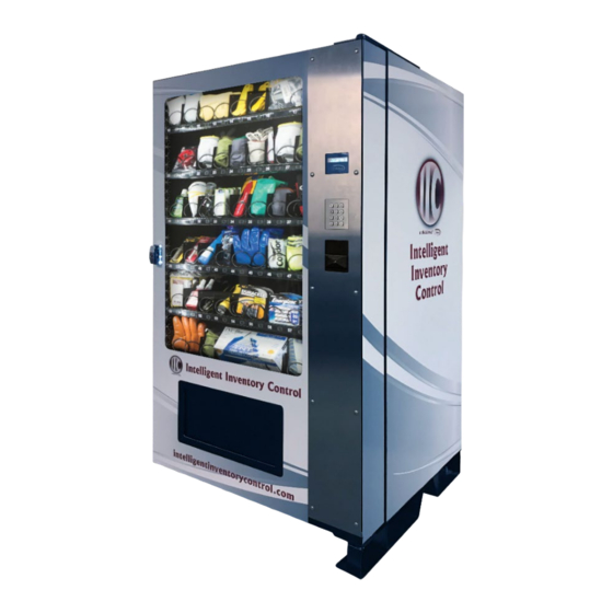
- Page 1 Intelligent Inventory Control A Division of IQ640 Service and Parts Manual Visit: intelligentinventorycontrol.com email: iic@seaga.com Revision 3 1 28 2019...
-
Page 2: Introduction
Once you have your vendor located, we suggest that you keep this manual for future reference, or you can view this manual online at seaga.com or intelligentinventorycontrol.com. Should any problems occur, refer to the section entitled “TROUBLESHOOTING”. It is designed to help you quickly identify a problem and correct it. -
Page 3: Table Of Contents
INTRODUCTION ................................2 MACHINE DETAILS ............................... 4 MACHINE OVERVIEW..............................6 CAUTIONS ..................................9 DOOR CLEARANCE ..............................10 LOADING PRODUCTS ..............................10 LOADING BAGGED OR BOXED ITEMS ........................10 RELOCATION OF TRAYS ............................10 COMBINING COLUMNS FOR WIDER PRODUCTS ....................12 LOCK .................................... -
Page 4: Machine Details
MACHINE DETAILS US Version 115 V Specifications Height 72” Width 39” Depth 37” Floor Space 9.75 Sq. Ft. 62.53 Cu. Packing Size Voltage (AC) 115V Hertz 60Hz Running Amperes 1Amp Watts 115 Watts Shipping Weight 528 lbs. EU and India Version, 230 V Specifications Height 184 cm... - Page 5 PHYSICAL CHARACTERISTICS • Finish Powder Coat paint ENVIRONMENT • Indoors only. ELECTRICAL REQUIREMENT US version requires one (1) 115 VAC 12 Amps grounded outlet. EU version requires one (1) 230 VAC 12 Amps grounded outlet. STANDARD COIL CONFIGURATION Custom configurations are available. Several kits are also available including AA, 9 volt, C Cell and D Cell Battery kits, large and small blade kits, a spray can kit as well as an adhesives and marking kit.
-
Page 6: Machine Overview
MACHINE OVERVIEW CAUTION: Certain procedures described in this manual require electrical power to the vending machine. Only trained personnel should perform these functions. Use extreme caution while performing the procedures marked with the voltage symbol shown here: CAUTION: Certain procedures described in this manual require a qualified, trained technician to perform the particular task at hand. - Page 7 1.) Remove Front and Back Door Protectors by removing four screws (2 front, 2 back) from the skid feet. (Fig. 2a) Remove screws, each side, front and back (4 screws total) 2.) On each side of the vending machine, remove four (4) screws from the front and back of the skid feet, remove plates.
- Page 8 Fig. 4 - Interior View VMC (Vending Machine Controller) Service Mode Button Display Board Power Switch Product Bin Door Wire Harness Revision 3 1 28 2019...
-
Page 9: Cautions
SECTION 2 INSTALLATION CAUTIONS Your vendor is intended for indoor use only. Excessive heat, cold or humidity levels will void your warranty; install only in climate controlled, indoor environments. For indoor machines the temperature range must be no higher than 32°C/90°F and no lower than 10°C/50°F with a relative humidity (Rh) level of no greater than 40%. -
Page 10: Door Clearance
Trays are fully loaded. To increase the length of the Helix Coil, plastic Product Pushers can be snapped on the end. Product Pushers can be purchased from Seaga’s Customer Care team. Fig. 5 – Loading Helix Coils Correct – load... - Page 11 Taller items that do not fit may require you to adjust the position of a tray in the machine. After planning what items you will stock in your IQ system, measure and decide which tray can be successfully moved to accommodate taller items. To relocate a tray, first test fit your items and determine how much extra room you will need.
-
Page 12: Combining Columns For Wider Products
6. Repeat for the right side rail. 7. Reinstall tray, taking care to position white locking lever in proper place. COMBINING COLUMNS FOR WIDER PRODUCTS Revision 3 1 28 2019... - Page 13 By combining two, three, four, five or even six columns into one, you can easily load wider items in your IQ system. This conversion requires kit SAI330 in different quantities depending on your column requirements. Please contact Seaga Customer Care for assistance and parts purchasing.
- Page 14 Note: To convert three single selections, remove both dividers and the right most coil as shown in steps 1 through 3. 4. Next, push down and hold the release latch located on the right side of the tray and lift the Product Tray slightly to clear the first tray stop only.
- Page 15 7. On the left motor of the two selections you are converting to a dual selection, remove two (2) screws fastening motor to tray back and unplug wire harness. Remove motor. Remove two (2) screws Unplug Wire Harness 8. Continue by installing the Coil Drivers into the Gears. Revision 3 1 28 2019...
- Page 16 9. On one of the Gears, which will be installed on the left side of the dual selection, install the Spacer onto the post of the coil driver. Note: This will be installed inside the tray as shown in #10 below. Note: It is very important to install the spacer in the tray with the flat sides of the spacer aligned into the grooves INSIDE the tray to prevent rotation of the spacer.
-
Page 17: Lock
Note: as one motor has been taken out of service, you must go into Service Mode on the VMC and run the Motor Home and Count (or Hardware, Motor Count on some VMCs) for proper operation of your new dual coil selection. The new dual selection will be identified on the VMC as the selection on the right side of the new dual space. -
Page 18: Menu Navigation
Figure 1 for location). With an established connection, the machine will provide you with a 10 digit code, which must be confirmed with Seaga to activate full function of your IQ. On initial setup: 1.) Plug the IQ640 into power and turn the main power on. -
Page 19: Chart Of Service Menus
To set Date and Time: 1.) Press the Service Mode button on the VMC (Fig. 4) 2.) Display will show Restock Options. 3.) Press the # key until Vendnovation appears on the display. 4.) Press 0 to enter this menu. 5.) Press # until the display shows Real Time Clock 6.) Press 0 to enter this menu. -
Page 20: Menus - Restock Options
MENUS – RESTOCK OPTIONS The Restock Options menu enables you to upload data after restocking the machine. Enter (#) Enter (#) Restock Options 1. 1 Restock to Picklist Scan your ID or enter with keypad to perform this function. Up Arrow (8) Enter (#) Uploads par value from web server settings. - Page 21 MENUS – CONFIGURATION The Configuration menu enables you to fine tune your IQ system and make customized changes. Configuration 3.1 Machine 1 3.1.1 Motor Range 3.1.2 Motor Rows Standard 3.1.3 Motor Mode Can/Bottle Locker Optic 1 3.1.4 Drop Sensor Optic 2 Vibration Enabled/Disabled 3.1.5 Auto-Reinstatement...
- Page 22 MENUS – VENDNOVATION The Configuration menu enables you to fine tune your IQ system and make customized changes. Displays the serial number of the VMC 5. Vendnovation 5.1 Serial Number Displays the MAC Address of the Ethernet hardware 5.2 MAC Address Use Keypad to enter 4 digit year 5.3 Real Time Clock 5.3.1 Enter Year...
-
Page 23: Delivery System
DELIVERY SYSTEM Your vendor consists of the VMC, Keypad, Display, Driver Motors, Product Trays, Coils and Delivery Bin. The customer enters their selection on the Keypad. The VMC signals the selection's Driver Motor to turn the Coil that vends the product into the Delivery Bin. -
Page 24: Product Sensor Electrical Specification
PRODUCT SENSOR ELECTRICAL SPECIFICATION There are four (4) wires from the sensor to the VMC as described below: Green +24V DC Vend Sensor Supply Voltage Brown Common Common (Supply and signal return) Grey +5V DC Signal Supply Voltage Yellow +5V DC Signal output TROUBLESHOOTING NO DISPLAY ON THE FRONT PANEL... -
Page 25: Custom Configurations And Optional Kits
The chart below shows the most common conversions IQ system users experience in the field and the kits available to adapt the system. If your particular requirement does not fall into these categories, please contact Seaga Customer Care to discuss your options. -
Page 26: Optional Spray Can Kit Installation
OPTIONAL SPRAY CAN KIT INSTALLATION In The Box Cassette Coil Tools Required Needle Nosed Pliers Phillips Screw Driver Installation 1. The tray above where you will install your Spray Can Kit must be adjusted upward to accommodate the height of the cassette. 2. - Page 27 3. Slide the tray toward you slowly, lifting slightly when the wheel hits the first tray stop on the rail. At this point, reach back on the right side of the cabinet and unplug the tray harness. 4. Lay the tray harness plug on top of the tray you’re removing and continue sliding the tray forward until it can be removed completely by lifting up slightly on the last tray wheel to free it from the side rails.
- Page 28 7. Repeat for the right side rail. 8. Continue working with the tray removed for better visibility. 9. The Spray Can Kit is installed by converting 3 single selections into one using the cassette and coil in the kit. 10. Begin by unlatching the tray you want to install the Spray Can Kit on and sliding it forward until you feel the wheel reach the first tray stop.
- Page 29 13. Install Spray Can Kit Cassette, using the divider hole to line up. Insert and re-use fastener from the center dividers to secure the cassette to the tray. Line up and Install Fastener 14. Snap Coil Retaining Hubs onto Coil. Revision 3 1 28 2019...
- Page 30 15. Install Coil Driver into Coil Retaining Hub. 16. Install Coil, Retainer and Driver assembly into center motor of the three selections you just converted, insuring that end of coil is in the 9:00 position. 17. Slide newly converted tray back into place. 18.
- Page 31 19. Load spray cans laying down in each section of the coil while lifting up the cassette loading platform. When all 6 spaces in the coils are loaded, close the cassette loading platform and load an additional 7 cans laying down to gravity feed as the coil stock is depleted.
-
Page 32: Optional Battery Kit Installation
OPTIONAL BATTERY KIT INSTALLATION In The Box Coil Retaining Hub Motor Coil Product Stabilizer Tools Required Needle Nosed Pliers Phillips Screw Driver Installation 1. Push down and hold the release latch located on the right side of the tray and slide the Product Tray toward you until it is in the Load Position. - Page 33 3. Push down and hold the release latch located on the right side of the tray and lift the Product Tray slightly to clear the first tray stop only. 4. Slowly slide the Product Tray toward you and down until it is in the Maintenance Position. Tray in Maintenance Position 5.
- Page 34 Remove two Unplug Wire Harness (2) screws 7. Install kit motor using the two screws removed previously and plugging in the wire harness. This motor may look the same as the current motor, but it has been modified to turn only 180 degrees for use with smaller product sizes such as batteries.
- Page 35 11. Install the newly assembled coil, hub and driver into the motor through the back of the tray, insuring the end of the coil is in the Home Position (approximately 9:00). 12. Slide stabilizer into coil, hooking slot over the washer on the Coil Retaining Hub. Slot in Stabilizer Hooks Over Washer in Coil Retaining Hub Revision 3...
- Page 36 13. Install a fastener screw at the front of the stabilizer to secure. Install fastener screw 14. Load batteries on each side of the Stabilizer as shown, insuring they are facing forward and undamaged to avoid product jams. Revision 3 1 28 2019...
-
Page 37: Optional Adhesive/Marking Kit Installation
OPTIONAL ADHESIVE/MARKING KIT INSTALLATION In The Box Motor Coil Retaining Hub Coil Tools Required Needle Nosed Pliers Phillips Screw Driver Installation 1. Push down and hold the release latch located on the right side of the tray and slide the Product Tray toward you until it is in the Load Position. - Page 38 3. Push down and hold the release latch located on the right side of the tray and lift the Product Tray slightly to clear the first tray stop only. 4. Slowly slide the Product Tray toward you and down until it is in the Maintenance Position. Tray in Maintenance Position 5.
- Page 39 6. Remove two (2) screws fastening motor to tray back and unplug wire harness. Unplug Wire Harness Remove two (2) screws 7. Install kit motor using the two screws removed previously and plugging in the wire harness. This motor may look the same as the current motor, but it is a custom design to turn only 180 degrees for use with smaller product sizes such as batteries.
- Page 40 10. Install the newly assembled coil, hub and driver into the motor through the back of the tray, insuring the end of the coil is in the Home Position (approximately 9:00). 11. Load adhesives or marking/paint pens on each side of the Coil Divider as shown, insuring they are facing forward and undamaged to avoid product jams.
-
Page 41: Optional Large Blade Kit Installation
OPTIONAL LARGE BLADE KIT INSTALLATION In The Box Stabilizer Bar Coils (2) Coil Retaining Hubs (2) Coil Driver Coil Drivers (2) Gear Spacer Gears (2) Non Drive Gear Retainer Tools Required Needle Nosed Pliers Phillips Screw Driver Installation 1. Push down and hold the release latch located on the right side of the selected tray and slide the Product Tray toward you until it is in the Load Position. - Page 42 2. If converting a dual selection, one of the coils in the next selection must also be removed. Start by removing the divider. 3. Remove the third (right) coil and coil driver by using the needle nosed pliers to squeeze the ends of the coil driver. Pull the coil and coil driver toward you to remove.
- Page 43 5. Install the stabilizer bar and screw from the kit in the area where the divider was previously. Stabilizer Bar Note: To convert three single selections, remove both dividers and the right most coil as shown in steps 1 through 3. 6.
- Page 44 9. Using the needle nosed pliers, gently press on the back of both Coil Drivers to remove them from the Motors. 10. On the left motor of the two selections you are converting to a dual selection, remove two (2) screws fastening motor to tray back and unplug wire harness.
- Page 45 12. On one of the Gears, which will be installed on the left side of the dual selection, install the Spacer onto the post of the coil driver. Note: This will be installed inside the tray as shown in #13 below. Note: It is very important to install the spacer in the tray with the flat sides of the spacer aligned into the grooves INSIDE the tray to prevent rotation of the spacer.
- Page 46 14. Then install the gear into the motor on the right side, making sure teeth on the two gears mesh properly. 15. Continue with step 5 to complete. 16. Note: as one motor has been taken out of service, you must go into Service Mode on the VMC and run the Motor Home and Count (or Hardware, Motor Count on some VMCs) for proper operation of your new dual coil selection.
-
Page 47: Optional Small Blade Kit Installation
OPTIONAL SMALL BLADE KIT INSTALLATION In The Box Stabilizer Bars (2) Coils (2) Coil Driver Coil Retaining Hubs (2) Gear Spacer Non Drive Gear Retainer Gears (2) Tools Required Needle Nosed Pliers Phillips Screw Driver Installation 1. Push down and hold the release latch located on the right side of the selected tray and slide the Product Tray toward you until it is in the Load Position. - Page 48 2. If converting a dual selection to this kit, start by removing the Coils and Coil Retaining Hubs with needle nosed pliers, squeeze the ends of the Coil Driver and pull the Coil Retaining Hub and coil toward you to remove. 3.
- Page 49 5. Install Left and Right Product Stabilizer Bars to create a “vee” shape as shown, hooking the slot in the back of the Product Stabilizer Bars into the washer on the Coil Retaining Hub. 6. Install fastening screws down through holes in the end of the Product Stabilizer Bars. Install fastening screws (2) 7.
- Page 50 Remove Screw and Center Divider 8. Next, push down and hold the release latch located on the right side of the tray and lift the Product Tray slightly to clear the first tray stop only. 9. Slowly slide the Product Tray toward you and down until it is in the Maintenance Position. 10.
- Page 51 11. Using the needle nosed pliers, gently press on the back of both Coil Drivers to remove them from the Motors. 12. On the left motor of the two selections you are converting to a dual selection, remove two (2) screws fastening motor to tray back and unplug wire harness.
- Page 52 13. Continue by installing the Coil Drivers into the Gears. 14. On one of the Gears, which will be installed on the left side of the dual selection, install the Spacer onto the post of the coil driver. Note: It is very important to install the spacer in the tray with the flat sides of the spacer aligned into the grooves in the tray to prevent rotation of the spacer.
- Page 53 15. Install Gears and Drivers on back of Tray, using the Non Drive Gear Retainer to install the Gear with Spacer on the left side: 16. Then install the gear into the motor on the right side, making sure teeth on the two gears mesh properly. 17.
- Page 54 Revision 3 1 28 2019...
- Page 55 Revision 3 1 28 2019...
-
Page 56: Cabinet Assembly
CABINET ASSEMBLY ITEM PART NO. DESCRIPTION SAI88002A CABINET STI70035 BRACKET, LEFT FRONT SAI88004 ASSEMBLY, ELECTRICAL BOX STI70039 PANEL, WIRING DIAGRAM STI70091 BRACKET, TRAY CONNECTOR STI573A LEGS SAI778 SUPPORT, DOOR STI87062 STOPPER, TRAY STI900 RAIL, TRAY LEFT STI901 RAIL, TRAY RIGHT HAC910 SPLIT NUT, T-HANDLE LOCK STI57038... -
Page 57: Door Assembly
DOOR ASSEMBLY ITEM PART NO. DESCRIPTION SAI89030 ASSEMBLY, DOOR HAC909 T-HANDLE STI89050 FRAME, DELIVERY DOOR SAI780 ASSEMBLY, HINGE, BOTTOM STI70058 COVER, DOOR LOCK PLI2082 CAP, TUBE, LED HAI990A TUBE, LED SAI777 ASSEMBLY, HINGE, TOP GLI953 GLASS HAI990 TUBE, LED SAI89013 ASSEMBLY, DELIVERY BIN ELI962D Revision 3... -
Page 58: Delivery Bin Assembly
DELIVERY BIN ASSEMBLY ITEM PART NO. DESCRIPTION SAI89012 DELIVERY BIN ASSEMBLY STI86007 CAM PLATE SAI89014 PUSH DOOR ASSEMBLY SAI779 ASSEMBLY, VEND SENSOR, LEFT SAI775 ASSEMBLY, VEND SENSOR, RIGHT STI89048 PANEL, DELIVERY BIN Revision 3 1 28 2019... -
Page 59: Electrical Panel Assembly
ELECTRICAL PANEL ASSEMBLY ITEM PART NO. DESCRIPTION STI70060 BOX, ELECTRICAL STI70010 BRACKET, SWITCH, MOUNTING ELI972 CIRCUIT BREAKER ELI946 FILTER ELC478 TRANSFORMER STI70059 BRACKET, TRANSFORMER ELI916 ON/OFF SWITCH Revision 3 1 28 2019... -
Page 60: Product Sensor, Right Side Assembly
PRODUCT SENSOR, RIGHT SIDE ASSEMBLY ITEM PART NO. DESCRIPTION STI70086 SENSOR BRACKET PLI609A SPACER ELI974 EMITTER FAI922 PRODUCT SENSOR, LEFT SIDE ASSEMBLY ITEM PART NO. DESCRIPTION STI70086 SENSOR BRACKET PLI609A SPACER ELI2169 DETECTOR FAI922 Revision 3 1 28 2019... -
Page 61: 10 Space Tray Assembly
10 SPACE TRAY ASSEMBLY ITEM PART NO. DESCRIPTION SAI87041 ASSEMBLY, WELDED TRAY FAI923 NUT, NYLOCK, M6 PLI802A WHEEL, TRAY HAI602 PIN, WHEEL, TRAY PLC958 PROFILE, PRICE SELECTION HAI976 PIN, PROFILE LABEL HOLDING STI70010A PARTITION, TRAY ELC920 MOTOR PLI721C SHAFT, GEAR MOTOR PLI331 HUB, COIL, RETAINER PLI87001... -
Page 62: Space Tray Assembly
5 SPACE TRAY ASSEMBLY ITEM PART NO. DESCRIPTION SAI87041 ASSEMBLY, WELDED TRAY FAI923 NUT, NYLOCK PLI802A WHEEL, TRAY HAI602 PIN, WHEEL, TRAY PLC958 PROFILE, PRICE SELECTION HAI976 PIN, PROFILE LABEL HOLDING STI70010A PARTITION, TRAY ELC920 MOTOR PLI721C SHAFT, GEAR MOTOR PLI536 GEAR PLI332... - Page 63 LIMITED WARRANTY Seaga warrants to the original purchaser that the equipment is free from defects in material and factory workmanship for a period of one (1) year from date of shipment. This warranty applies only if the equipment has been serviced and maintained in strict accordance with the instructions presented in the Operator’s Manual and no unauthorized service, repair, alteration or disassembly has been performed.
Need help?
Do you have a question about the Intelligent Inventory Control IQ640 and is the answer not in the manual?
Questions and answers