Table of Contents
Advertisement
Advertisement
Table of Contents

Related Manuals for Seaga SM16S


Summary of Contents for Seaga SM16S
- Page 1 SERVICE and PARTS MANUAL Rev.1.2 – 7.2018.EL950.1.3.1086C...
-
Page 2: Equipment Inspection
Once you have your vendor located, we suggest that you keep this manual for future reference, or you can view this manual online at www.seaga.com. Should any problems occur, refer to the section entitled “TROUBLESHOOTING”. It is designed to help you quickly identify a problem and correct it. -
Page 3: Specifications
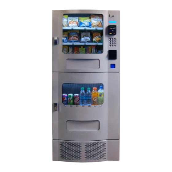
SPECIFICATIONS The vending machine is comprised of two (2) units - Snack Unit (SM16S) and Beverage Unit (SM7RD). Installation and setup of these units is explained in the next sections of this manual. Machine Description Snack Unit Beverage Unit SM16S... -
Page 4: Installation
Reporting damages and the seeking of restitution is the responsibility of the equipment owner. The factory is willing to assist you in this process in any way possible. Feel free to contact Seaga Customer Care with questions you may have on this process. Once you have your vending machine located, we suggest that you keep this manual for future reference. - Page 5 Once the machines have been unpacked and placed in their permanent location, the electrical connection and mechanical connection must be made. Tools required: Adjustable wrench and Philips screwdriver. For optimal installation, follow the order of connections as outlined below: 1. Mechanical Connection between Snack and Beverage Units: The Snack and Beverage units must be screwed together for safety purposes.
- Page 6 Figure 3– Making Drink Connections MENUS Button Drop Sensor (ELI2310) Harness connection Beverage main harness attaches to bottom connector port The Beverage Unit has a live product display that is lit by LED lighting. Locate the LED Light harness on the inside of the Beverage Unit Door. Insert the LED Light harness up through the Snack Unit as done for the other connections.
- Page 7 Figure 5 – Main Power Connection Connect the snack unit to the beverage unit with the jumper power cord. Then connect the beverage unit power cord to wall socket with power. Using a power strip is recommended. CAUTION: to avoid risk of electrical shock, the power to the wall socket should be made last of all connections.
-
Page 8: Product Loading
1. To Load Product in Snack Unit: a. Pull the desired product tray all the way forward. Product tray will tilt down. Note: Pull out only one (1) product tray at a time b. Place product in proper size coil. Note: Bottom of product must rest on the product tray and not on the Coil. - Page 9 COIL ADJUSTMENT If you are required by a location to vend a product that does not fit into the standard coil installed, you may need to order a different coil and install it. To replace a coil: 1. Remove the Coil from the Coil Driver by lifting the back of the coil up off the coil driver. You will need to move the bottom of the coil clear of the coil driver to completely remove the coil.
- Page 10 BEVERAGE UNIT Figure 10 – Factory setup for your machine. Back of machine Front of machine Vertical Product Columns – Load products horizontally (laying down) Your vending machine has been set by the factory for the following products and groups (see chart): Selection 140 –...
- Page 11 1.) For most bottles, place top of the first bottle against the front of the column. Place the second bottle to the rear of the column, facing the bottom of the bottle with the bottom of the first bottle. See Figure 10. Load 12 oz.
- Page 12 Retainer 2.) 20 oz/591 ml Bottles are loaded laying down, two deep in each column. Load the first bottle so that the top touches the back of the column. The next bottle should also be loaded with the top toward the back of the column, positioned against the bottom of the first bottle.
- Page 13 Retainer Adjusted within ½” of product Locking Arm Secured Note: There are many variations of packaging. These instructions are meant to be a guideline. If you have packaging that isn't mentioned or shown, setup and testing will be necessary to ensure proper vending. For 12 oz.
- Page 14 Back By adjusting the Shims and/or changing the cams any column can be converted to cans or bottles. Contact Seaga Customer Service if you need assistance. Figure 14– Side Spacer, Small, LH, Side Spacer, Large, LH and Side Spacer, RH...
- Page 15 Side Spacer, Large, LH Side Spacer, Small, LH Part # SA846 Part # ST691 Side Spacer, RH LIVE DRINK PRODUCT DISPLAY Part # SA689 Figure 15 – Auger Insert, Large Auger Insert, Auger Insert, Large Narrow Product Part # PLI2182 Part # PLI2206 Figure 16 –Back Spacer Part # SA484...
- Page 16 Your machine has a live product display shelf for the drinks. Take care to use packaging that is in perfect condition and products that are still within their expiration date to present the best possible advertisement to your potential customers. To display your products: 1.) Remove the Drink Display Back Panel by loosening and removing the thumb screws located on either side of the panel.
- Page 17 DISPLAY The LCD Display (Fig. 18) is a two line, 20 character text display panel located on the front of your vending machine. The display interacts with the customer to show the amount of money entered into the vendor and the cost of their selection among other information as programmed. The display also shows the operator the Service Mode functions for setting the vendor.
-
Page 18: Service Mode Navigation
KEYPAD * = Exit or Next # = Save SERVICE MODE The operation of the machine can be adjusted by entering service mode by pressing the MENUS button on the VMC circuit board and then accessing the appropriate operation. Price setting, audit display and operating modes can be read and adjusted from here. - Page 19 VMC – VENDING MACHINE CONTROLLER Enter Service Mode by pressing the MENUS Button on the VMC Circuit board. (Fig. 19) Figure 19 – VMC and Menus Button MENUS Button Rev.1.2 – 7.2018.EL950.1.3.1086C...
-
Page 20: Menu Hierarchy
MENU HIERARCHY PRICE CASH QTY/TUBE CONFIGURATION OPTIONS Date/Time All Items All Items Enter this mode Forced Vend when priming/filing Health Safety Bill Escrow the changer Selection Selection Language Multi-Vend Coupon All Items – Type Free Vend Token Row – Type Fast Change Selection –... - Page 21 SERVICE MODE 1. PRICE PROGRAM Price Program is used to set the prices for All Items, by Row or by individual Selection. Save time and set All Items to the most common price, going back to Row or Selection for different prices as required.
- Page 22 Coupons Press 4 for Coupons * -Exit, no change Coupon1 Press 1 for Coupon1 (or corresponding number for * -Exit, no change #-Save additional coupons, up to Coupon5) All Items (Current Setting) Press 1 for All Items * -Exit, no change 1-Edit All Items (Choice Flashing) Press 1 to toggle On/Off...
- Page 23 *-Exit, no change #-Save Coupon1: $(New Value) Press # to Save the Coupon1 Value setting * -Exit, no change #-Save Press * two times to continue to Coupon2 – 5 or press * five Price Program times to exit. COUPON BY ITEM STEP DISPLAY Press Service Mode Button...
- Page 24 Tokens Press 5 for Tokens * -Exit, no change Token1 Press 1 for Token1 (or corresponding number for * -Exit, no change #-Save additional tokens, up to Token5) All Items (Current Setting) Press 1 for All Items * -Exit, no change 1-Edit All Items (Choice Flashing) Press 1 to toggle On/Off...
- Page 25 *-Exit, no change #-Save Token1: $(New Value) Press # to Save the Token1 Value setting * -Exit, no change #-Save Press * two times to edit Token2 – 5 or press * five times to Price Program exit. TOKEN BY ITEM STEP DISPLAY Press Service Mode Button...
- Page 26 COMBO Combos are a group of 2-5 selections that can be sold together for one price. For example, a price of $7.50 the customer will be able to purchase a bagged snack (110), a snack from the third tray (131) and a drink (142) which will all vend when the Combo Selection is used.
-
Page 27: Cash Counters
2. CASH COUNTERS Cash Counters displays the total vend count and the total sales value for the machine, for All Items, by Row or by individual Selection. Note: The resettable counters can be cleared. ALL ITEMS STEP DISPLAY Press Service Mode Button Motor Count or Error Code ** Press 2 for Cash Counters Cash Counters... -
Page 28: Health & Safety
3. QTY/TUBE Enter this menu when priming the changer with coins. As you load coins from the front door in the coin slot, this menu will keep track of the quantity and monetary amount which enables the VMC to know that change can be made during sales transactions. STEP DISPLAY Press Service Mode Button... - Page 29 ON/OFF *-Exit, no change 2- Toggle On/Off # to Save Selection – Use number keys to select Press 3 to change one Selection ON/OFF *-Exit, no change 3- Toggle On/Off # to Save Press 2 to change Lower Zone Lower Zone All Items ON/OFF -Exit, no change Press 1 to change All Items...
-
Page 30: Selection: Type
ROW: TYPE (Trays 110, 120, 130 must be set to Snack/Tray, 140 to Can) STEP DISPLAY Press Service Mode Button Motor Count or Error Code ** Press 4 for Configuration Configuration Row – Use number keys to enter Row * -Exit, no change 1 –... - Page 31 SPACE TO SALES (StS) This feature is not used in this model and should be set to OFF. STEP DISPLAY Press Service Mode Button Motor Count or Error Code ** Press 4 for Configuration Configuration StS (Current setting) Press 8 for Space to Sales * -Exit, no change 8-Edit StS Off...
-
Page 32: Beep Enable
ADVANCED A password is required to enter this menu. The factory default password is 2314. The following sub-menus are available under this sub-menu: • Beep Enable • Temp Optics Disables Selection Style • • • Motor Type BEEP ENABLE STEP DISPLAY Press Service Mode Button Motor Count or Error Code **... -
Page 33: Motor Type
MOTOR TYPE Note: Must be set to 3 Wire. STEP DISPLAY Press Service Mode Button Motor Count or Error Code ** Press 4 for Configuration Configuration Password: Press 0 for Advanced Config Use keypad to enter password Motor Type (Current Setting) Press 3 for Motor Type menu * -Exit, no change 3-Edit Motor Type (Choice Flashing) - Page 34 5. OPTIONS The following sub-menus are included in the Options Menu: Forced Vend Optical Vend • • • Bill Escrow • POS Message Multi Vend Set Point • • • Free Vend • Drop Sensor Fast Change • FORCED VEND Forces the customer to complete a purchase once they have made payment in any form.
- Page 35 STEP DISPLAY Press Service Mode Button Motor Count or Error Code ** Press 5 for Options Menu Options Multi Vend (Current Setting) Press 3 for Multi Vend Menu * -Exit 3-Edit Multi Vend (Choice Flashing) Press 3 to toggle between ON and OFF * -Exit #-Save Multi Vend (New Setting)
- Page 36 All Items (New Setting) Press # to save the setting -Exit 3-Edit Press * four times to exit 0.00 OPTICS BY ROW STEP DISPLAY Press Service Mode Button Motor Count or Error Code ** Press 5 for Options Menu Options Press 6 for Optical Vend Menu Optical Vend Row: --...
- Page 37 SET POINT Displays the factory default Set Point temperature for each machine type. See Temp section for the specific machine refrigeration modes. Ambient snack machines without a refrigeration system will display 43 °F. These temperatures may be adjusted, however it is not advised without direction by an authorized technician.
- Page 38 DISCOUNT This menu uses various sub-menu settings to allow a different price for selections at different times or on different days. STEP DISPLAY Press Service Mode Button Motor Count or Error Code ** Press 6 for Password (Advanced Features) Menu Password Enter Password (default 2314) Advanced Features...
- Page 39 * -Exit #-Save Enable (New Setting) Press # to save the setting * -Exit 9-Edit Press * five times to exit to Sales Mode 0.00 DISCOUNT BY ROW Note: Make sure All Items setting in the Discount Advanced Features menu is set to OFF. STEP DISPLAY Press Service Mode Button...
- Page 40 Discount (New Value) Press 7, then enter new Discount Value (Enter the new * -Exit #-Save price at which to sell the item) Discount (New Setting) Press # to save the discount value * -Exit #-Save Press * two times to return to Discount menu Discount Enable (Choice Flashing) Press 9 for Enable Discount menu...
- Page 41 Press * two times to return to Discount menu Discount Press 6 two times for Stop Time menu Stop Time New Time Press 6, then enter Start Time in 24-hr time (HH:MM) * -Exit #-Save New Time Press # to save the time * -Exit 6-Edit Press * two times to return to Discount menu...
- Page 42 Alt Rules (Current Setting) Press 2 to set Alt Rules * -Exit 2-Edit Alt Rules (Choice Flashing) Press 2 to toggle ON/OFF (default ON) * -Exit #-Save Alt Rules (New Setting) Press # to save the setting * -Exit 3-Edit Press * two times to exit 0.00 UNCONDITIONAL ACCEPTANCE...
- Page 43 If a row or individual selection has been set for Shutdown, the same message displays once every time the customer makes that selection or selections (row). NOTE: the correct time and date must be set so that the shutdown intervals work correctly. See Time and Date section of this manual.
- Page 44 Lighting OFF leaves lights on during Energy Saving interval Lighting (New Setting) Press # to save the setting * -Exit 8-Edit Press * five times to exit to Sales Mode 0.00 SHUTDOWN BY ROW STEP DISPLAY Press Service Mode Button Motor Count or Error Code ** Press 6 for Password (Advanced Features) Menu Password...
- Page 45 SHUTDOWN BY SELECTION STEP DISPLAY Press Service Mode Button Motor Count or Error Code ** Press 6 for Password (Advanced Features) Menu Password Enter Password (default 2314) Advanced Features Press 5 for Shutdown Shutdown Press 1 for Interval1 (2 for Interval2, and so on) Interval1 Selection: -- Press 3 for Selection menu...
-
Page 46: Energy Savings
Lighting (New Setting) Press # to save the setting * -Exit 8-Edit Press * five times to exit to Sales Mode 0.00 ENERGY SAVINGS Use this menu to set a non-health safety machine to run at a higher than normal temperature during set times. - Page 47 Lighting OFF leaves lights on during Energy Saving interval Lighting (New Setting) Press # to save the setting * -Exit 8-Edit Press five times to exit to Sales Mode 0.00 PAIR Not applicable. No motors should be paired. STEP DISPLAY Press Service Mode Button Motor Count or Error Code ** Press 6 for Password (Advanced Features) Menu...
-
Page 48: Test Modes
Selection: (Current Selection) Enter selection to test and wait * -Delete Selection: (New Selection) Repeat for any other selections or * -Delete Press * to exit to Sales Mode 0.00 9. SELECTION: ALL This function tests all motors in sequence automatically. To stop the test, press * to exit. NOTE: All selections should be empty prior to performing this test. - Page 49 VMC Scale Factor There is a conflict with one or more Review manuals and settings for MDB setting from the installed MDB installed MDB devices to make devices. sure they are compatible. VMC Selection SW A keypad selection button is stuck in Determine reason why keypad the depressed position.
- Page 50 Vend Sensor Errors Error Message Description Possible Solutions Optical Sensor Error Not Applicable Coin Changer Errors Error Message Description Possible Solutions Coin Mech Comm VMC does not have communication Check MDB Harness to changer. with the coin changer. Check for power on changer. See changer service manual.
- Page 51 Card RDR1 or 2 Comm VMC does not have communication Check MDB Harness to card with the card reader. reader. Check for power on card reader. Card RDR1 or 2 Err The card reader reports an error See card reader service manual. NOTE: Errors are cleared after the problem detected has been resolved.
-
Page 52: Payment Systems
one hand pinching the lugs of the shaft. Push the shaft through the back of the vend motor, freeing up the coil/driver/shaft assembly for removal. Note: This operation is more difficult with smaller Coils. e. Remove the two Phillips head screws that are securing the motor to the product tray. Disconnect Wires of the Vend Motor, paying close attention to the orientation of the motor plug wire connector. - Page 53 Figure 21 - Coin Changer Coin Return Lever Lever Coin Funnel Diagnostic LED User Interface Buttons for Coin Tubes A, B, C, D, E Channel Acceptor Gate Assembly Cover Cassette Latch Coin Coin Tubes Cassette Clearing Coin Jams 1. Unplug the machine from the power source 2.
- Page 54 Coin Ramp – keep clean 5. Open the Coin Channel Cover by using the tab on the left side to pull forward 6. Check this area for any jammed coins Rev.1.2 – 7.2018.EL950.1.3.1086C...
- Page 55 Removal of Coin Changer To Remove the Coin Changer: a. Disconnect the power to the machine – this is very important to avoid damaging not only the coin changer but your VMC. Failure to disconnect power before performing this operation will void your warranty. b.
- Page 56 Lift Changer and remove. Bill Validator The Bill Validator allows your customers to pay for their purchase with paper currency. Your Bill Validator is installed at the factory, and is set to validate $1 and $5 bills, but will not accept bills if the coin tubes are empty.
- Page 57 Figure 22 – Bill Validato Bill Collection Box (4) Mounting Nuts Lower Housing Removing Bill Validator From time to time it may be necessary to remove the Bill Validator for cleaning and clearing jams. 1. To remove the Bill Validator a.
- Page 58 Four (4) Mounting Nuts f. Remove Bill Validator Nut is horizontally across from upper nut) Clearing Bill Jams It is possible that a torn or damaged bill can jam within the Bill Validator, putting it out of service. 1. To Clear a Jam. a.
- Page 59 d. Inspect and remove jammed bill. e. Replace lower unit to resume normal operation. REFRIGERATION DECK Your Drink unit incorporates a high efficiency refrigeration system having two air circulation fans to chill the cans and bottles. The refrigeration unit can be easily accessed by opening the Drink unit door and sliding the front grill up and out.
-
Page 60: Cleaning The Condenser
CLEANING THE CONDENSER Dust and dirt restricts good airflow and cooling of the condenser, causing the refrigeration unit to not chill the beverages properly. Remove the front bottom panel of the beverage unit. Brush the dirt and dust from the condenser fins. You can also blow canned air, available at computer and office supply stores, on the condenser or vacuum clean it. - Page 61 Installation in outside or environments without climate control will compromise cooling, potentially damage your machine and void the warranty. If further assistance is needed, please contact Seaga Customer Care or a local refrigeration technician. Q. My drinks are not cooling at all.
- Page 62 2. Insure spacers are properly installed. 3. See seaga.com for helpful videos on how to properly load a vertical drop system. Q. A product keeps hanging up or getting stuck. What can I do? 1. The product may be loaded incorrectly in the coil or the product may be in the wrong sized coil.
-
Page 63: Frequently Asked Questions
Q. Are there different coils that will hold a larger number of products (more product spaces)? A. For other coil options, please call Seaga Customer Care. Q. My Drink Unit door will not line up and lock. What can I do? A. - Page 64 Bill Validator My vendor won’t accept bills, what do I do? 1. Make sure the bill acceptor is clean and there are no jams or debris inside of the acceptor. Beverage Vending My beverages aren’t vending at all. 1. Make sure all items are loaded correctly. 2.
- Page 65 Figure 24 – Snack Unit (SM6S) ITEM PART NO. DESCRIPTION SA9215A DOOR WE9225A VERTICAL SHELF AND COMPONENTS ELC478 TRANSFORMER SA9221 8-SELECTION PRODUCT TRAY SA9222 4-SELECTION PRODUCT TRAY SA9009 MAIN CABINET ELC952B POWER CORD, JUMPER ELI950 Rev.1.2 – 7.2018.EL950.1.3.1086C...
- Page 66 Figure 25 – Snack Unit Door (SM16S) ITEM PART NO. DESCRIPTION HAC246 and HAC247 T-HANDLE LOCK SAI92005a DOOR ASSEMBLY HAI351 HINGE SAI92012 DELIVERY DOOR CARD READER Rev.1.2 – 7.2018.EL950.1.3.1086C...
- Page 67 Figure 26 – Beverage Unit (SM7RD) ITEM PART NO. DESCRIPTION SA9401 MAIN CABINET SAI56012A PRODUCT DELIVERY SYSTEM REI801F REFRGERATION DECK ASSEMBLY WE9410 FRONT PANEL SA9420 DOOR ELC348 POWER CORD ELI2293A MAIN HARNESS BEVERAGE UNIT Rev.1.2 – 7.2018.EL950.1.3.1086C...
- Page 68 Figure 27 – Beverage Unit Door (SM7RD) ITEM PART NO. DESCRIPTION HAI246 and HAI247 T-HANDLE LOCK SAI94006 DOOR SA94010 DELIVERY DOOR PLI2106 BEVERAGE DISPLAY COVER PLI615 GASKET Rev.1.2 – 7.2018.EL950.1.3.1086C...
- Page 69 Figure 28 – Vertical Shelf and Components ITEM PART NO. DESCRIPTION SAI92008 VERTICAL SHELF ELI909 VFD DISPLAY VARIES BILL VALIDATOR SAI920 COIN RETURN FLAP PLI607 COIN RETURN CUP SAI92024 COIN DROP CHUTE SAI92029 COIN RETURN CHUTE VARIES COIN CHANGER SAI92023 COIN INSERT CHUTE SAI92016 COIN RETURN MECHANISM...
- Page 70 Figure 29 – Refrigeration Deck ITEM PART NO. DESCRIPTION SAI94021 DECK BASE REI830 EVAPORATOR REI872 COMPRESSOR REI300 ELI764 24 VOLT RELAY ELI595 TERMINAL BLOCK PLI612 CONDENSATE TRAY REI612 CONDENSER MOTOR ASSEMBLY REI609A CONDENSER Rev.1.2 – 7.2018.EL950.1.3.1086C...
- Page 71 Figure 30 – Wiring Diagram Rev.1.2 – 7.2018.EL950.1.3.1086C...
-
Page 72: Limited Warranty
Freeport IL 61032 Seaga will repair or replace, at our option, any covered part which meets the provisions herein during the warranty period. It is our discretion to replace defective parts with comparable parts. Seaga reserves the right to make changes or improvements in its products without notice and without obligation, and without being required to make corresponding changes or improvements in equipment already manufactured or sold.
Need help?
Do you have a question about the SM16S and is the answer not in the manual?
Questions and answers