
Subscribe to Our Youtube Channel
Related Manuals for Seaga Quick Break Combo QB218


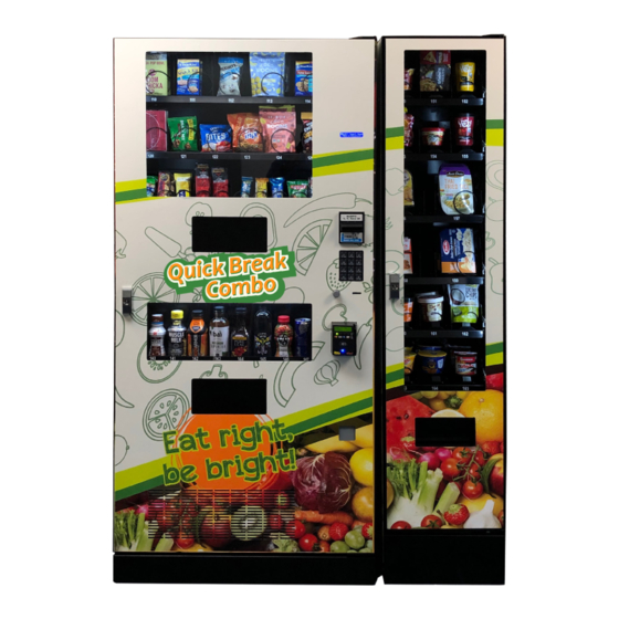
Summary of Contents for Seaga Quick Break Combo QB218
- Page 1 Quick Break Combo with optional Entree Unit QB218 SERVICE and PARTS MANUAL 700 Seaga Drive, Freeport, IL 61032, U.S.A. | visit: seaga.com | email: info@seaga.com QB218 6.1.2019 vers 1.0...
-
Page 2: Introduction
Once you have your vendor located, we suggest that you keep this manual for future reference, or you can view this manual online at www.seaga.com. Should any problems occur, refer to the section entitled “TROUBLESHOOTING”. It is designed to help you quickly identify a problem and correct it. -
Page 3: Table Of Contents
Table of Contents Introduction ............................2 Preliminary Information ........................4 Initial Setup ............................6 Equipment Setup ..........................9 Loading Snack Trays ..........................9 Removing Snack Trays ........................11 Adjusting Coils ...........................12 Replacing Snack Motors ........................13 Loading Product Lanes ........................14 Customer Interface ..........................20 Setting Up And Loading The Payment Systems ..................21 Coin Changer ............................21... -
Page 4: Preliminary Information
Preliminary Information Figure 1 – The QB218 Vending System Aux Unit Main Unit - VMC optional Aux. Display Window Display Window Display Product Delivery Door Aux. Door Main Door Handle and Lock Handle and Lock keypad Display Window Aux Product Delivery Door Product Delivery Door... - Page 5 Machine Description Main Unit Aux. Unit Height (in) 73.5 73.5 Width (in) Depth (in) 28.25 28.25 Volts (V) Frequency (Hz) Watts (W) Current (A)* Figure 2 - Interior of machine and controls Display Bill Validator Beverage Harness Vertical Drop Door Hasps Coin Changer QB218 6.1.2019 vers 1.0...
-
Page 6: Initial Setup
Power Requirements The wall receptacle used for your vendor must be properly polarized, grounded and of the correct voltage. Operating the QB218 system from a source of low voltage will VOID YOUR WARRANTY. Each QB218 system should have its own 15 Amp electrical circuit that is protected by a circuit breaker or fuse conforming to local power safety regulations. - Page 7 Front Door Unlocking – Insert the key into the lock and turn the key clockwise until the T-Handle pops out – then turn the T-Handle counter-clockwise 3 or more revolutions until the door can be pulled open. Locking – Close the door firmly. Turn the lock housing one revolution clockwise and pull to test that the lock spear has engaged with the locking mechanism.
- Page 8 Figure 3 – Auxilary Unit Bolts Attach with provided bolts and washers Disconnect power from Main Unit. Connect Wire Harness from the Entree Unit to the Main Unit. (Figure 4) Reconnect power to Main Unit. Figure 4 – Wire Harnesses IQ380 Aux Unit IQ380 Main Unit Aux.
-
Page 9: Equipment Setup
Theory of Operation for Snack & Entree Trays When a snack vends, power is sent to the motor (that drives the coil) and it turns until the motor hub is back to the internal “home switch” then it stops and the vend is considered to be complete. The motor simply rotates 360 degrees and stops. - Page 10 Products Make sure your products are appropriate for the column and coil you are placing them in. Do not force products that are too wide into a narrow tray or too tight coil as this will cause vend problems for your customers.
-
Page 11: Removing Snack Trays
Removing Snack Trays It is sometimes necessary to replace a snack tray or you may find it easier to work on certain elements of a tray if it is removed from the vending system cabinet. Figure 7 – Tray Harnesses Tray 110 Harness Tray 120 Harness Tray 130 Harness... -
Page 12: Adjusting Coils
Figure 8 – Remove the tray Tray 130 Harness Lift tray free Adjusting Coils If you are required by a location to vend a product of a non-standard size, you may need to order a different coil and install it. Replacing a coil is easier with the tray removed, as described in the last section. To replace a coil: 1. -
Page 13: Replacing Snack Motors
If you are experiencing vending issues with certain products, you may need to adjust the coil rotation to better provide the momentum to push the snack off the tray and into the delivery area. To adjust the coil rotation: 1. Squeeze the two tabs on the back of the coil driver and pull the coil driver and coil toward the front of the tray to remove it. -
Page 14: Loading Product Lanes
Theory of Operation of Beverage Vending The beverage section uses (2) Drop Sensors (vibration sensors) to detect the product drop. In normal operation, the auger will rotate counter clockwise to drop a product onto the delivery chute. Upon detection of the product drop by these sensors, the motor (driving the auger) will stop and the vend is considered complete. - Page 15 Figure 13 – Retainer in Load Position Retainer 2. 20 oz/591 ml Bottles are loaded laying down, two deep in each column. Load the first bottle so that the top touches the back of the column. The next bottle should also be loaded with the top toward the back of the column, positioned against the bottom of the first bottle.
- Page 16 Note: There are many variations of packaging. These instructions are meant to be a guideline. If you have packaging that isn’t mentioned or shown, setup and testing will be necessary to ensure proper vending. Below is an overhead view of several product types loaded and an illustration of accessory placement: Figure 15 –...
- Page 17 *Note: see list below for Loading Group by Selection; this illustration is not of your machine set up Back of Machine Front of Machine To accommodate a wide variety of packaging, spacers and other accessories are provided to assist with vending performance.
- Page 18 15 oz Starbucks Side Spacer, Small, LH Alternate top and 443 ml Doubleshot Back Spacer bottom Coffee 12 oz Most Brands, Side Spacer, large, LH Alternate top and 355 ml Standard Size bottom Cans 13.7 oz Glass Bottle Starbucks Side Spacer, large, LH Alternate top and 405 ml Frappuccino...
- Page 19 Figure 17 – Auger Inserts Auger Insert, Large Auger Insert, Narrow Product Part # PLI2182 Part # PLI2206 Figure 18 –Back Spacer Part # SA484 Unlike the snack section of the vending system, the products that will vend are not viewable by your customers when they are positioned in the vertical drop columns.
-
Page 20: Customer Interface
Loading Entrees Entrees are loaded in spiral equipped columns very similar to the snack section of the IQ380 vending system. Please review the procedures in that section of the manual to assist you with loading the entrees. Customer Interface Display The LCD Display (Fig. -
Page 21: Setting Up And Loading The Payment Systems
Setting Up and Loading the Payment Systems Coin Changer The Coin Changer receives and returns change to customers. The Coin Changer will accept Dollar Coins, Quarters, Dimes, and Nickels. Once the coin tubes reach the required inventory level, all other coins will be routed into the coin overflow tray. -
Page 22: Clearing Coin Jams
Clearing Coin Jams 1. Unplug the machine from the power source 2. Unlock and open the Front Door 3. Open the Acceptor Gate Assembly by pulling forward on the Coin Funnel 4. Check for coin jams in this area. Note: the ramp in this area should also be cleaned on a regular basis to insure trouble-free operation. -
Page 23: Removal Of Coin Changer
6. Check this area for any jammed coins Removal of Coin Changer To Remove the Coin Changer: a. Disconnect the power to the machine – this is very important to avoid damaging not only the coin changer but your VMC. Failure to disconnect power before performing this operation will void your warranty. b. -
Page 24: Bill Validator
c. Lift up on the white lever on the top left side of the coin mechanism d. Tilt the Discriminator assembly forward and lift off main housing. Note: the discriminator will still be at- tached by a cable. e. Loosen the three (3) Mounting Screws f. - Page 25 c. Close top door on bill collection box after bills are retrieved Figure 22 – Bill Validator Bill Collection Box (4) Mounting Nuts Lower Housing QB218 6.1.2019 vers 1.0...
-
Page 26: Removing Bill Validator
REMOVING BILL VALIDATOR From time to time it may be necessary to remove the Bill Validator for cleaning and clearing jams. a.Disconnect the power to the machine – this is very important to avoid damaging not only the bill validator but your VMC. Failure to disconnect power before performing this operation will void your warranty. -
Page 27: Clearing Bill Jams
Clearing Bill Jams It is possible that a torn or damaged bill can jam within the Bill Validator, putting it out of service. 1. To Clear a Jam. a. Remove Bill Collection Box as instructed in Bill Retrieval and inspect for a jammed bill b. -
Page 28: Programming
PROGRAMMING Enter Service Mode by pressing the MENUS Button on the VMC Circuit board. (Fig. 23) Figure 22 – VMC and Menus Button SERVICE MODE NAVIGATION Use the 0 through 9 keys to access the various menus and sub-menus. Use the “*” key on the keypad to Exit without changing or to go back (Previous). Use the “#”... -
Page 29: Service Mode
SERVICE MODE 1. .PRICE PROGRAM Price Program is used to set the prices for All Items, by Row or by individual Selection. Save time and set All Items to the most common price, going back to Row or Selection for different prices as required. The value for Coupons accepted by pre-programmed validators and Tokens accepted by pre-pro grammed coin changers as well as Combo pricing are also set in this menu. - Page 30 SELECTION STEP DISPLAY Press Service Mode Button Motor Count or Error Code ** Press 1 for Price Program Price Program Selection: -- $--.-- Press 3 for Selection *-Exit, no change Use number keys on the keypad to set new Selection: (New Selection and Price) price, including cents.
- Page 31 Coupon1: $0.00 Enter Coupon1 value *-Exit, no change #-Save Coupon1: $(New Value) Press # to Save the Coupon1 Value setting *-Exit, no change #-Save Press * two times to continue to Coupon2 – Price Program 5 or press * four times to exit. COUPON BY ROW STEP DISPLAY...
- Page 32 Coupon1: $(New Value) Press # to Save the Coupon1 Value setting *-Exit, no change #-Save Press * two times to continue to Coupon2 – Price Program 5 or press * five times to exit. COUPON BY ITEM STEP DISPLAY Press Service Mode Button Motor Count or Error Code ** Press 1 for Price Program Price Program...
- Page 33 TOKEN IMPORTANT: This option requires a programmed changer and allows you to set the value of tokens accepted. Note: If Space to Sales Whole Machine is On and you are setting Tokens by Row, the Row must be set to Row 1. If using both coupons and tokens, there are only five selection combinations available. For example, if Coupon1 is set for “All”...
- Page 34 All Items (Current Setting) Press 1 for All Items to verify Off *-Exit, no change 1-edit All Items (Choice Flashing) Press 1 to toggle On/Off if necessary *-Exit, no change 1-edit Press # to Save the new setting to Off if All Items (New Setting) necessary *-Exit, no change #-Save...
- Page 35 Selection: -- Press 3 to enter an Item *-Exit Selection: XX (Current Setting) Enter Item Number *-Exit, no change #-Edit Selection: XX (Choice Flashing) Press 1 to toggle Item On/Off *-Exit, no change #-Save Selection: XX (New Setting) Press # to save the setting *-Exit, no change #-Edit Press * twice to return to the Token 1 menu Token1...
- Page 36 Enter Range number, then enter selection numbers Note: A Range represents the first selection(s) in the combo. In our example, the range Range1: --- to --- would be selection 110 to 110. A second *-Exit, no change #-Save range would be set for selection 131 to 131 and the third range for 142 to 142.
- Page 37 STEP DISPLAY Press Service Mode Button Motor Count or Error Code ** Press 2 for Cash Counters Cash Counters Press 2 for Row Use keypad to choose Row. Press 1 for Historical Count Hist Count -- Press 2 for Historical Cash Hist Cash $--.-- Press 3 for Reset Count Res Count --...
- Page 38 CONFIGURATION The following sub-menus are included in the Configuration Menu: • Date/Time • Selection – Type • Health Safety • Auto Reinstate • Language • StS • All Items – Type • StS Custom • Row – Type • Advanced Config* DATE/TIME STEP DISPLAY...
- Page 39 Selection – Use alpha and number keys to select row ON/OFF Press 3 to change one Selection *-Exit, no change 3- Toggle On/Off # to Save Press 2 to change Lower Zone Lower Zone All Items ON/OFF *-Exit, no change Press 1 to change All Items 1- Toggle On/Off # to Save...
- Page 40 ROW: TYPE (Trays 11, 12, 13 must be set to Snack, 14 to Can) STEP DISPLAY Press Service Mode Button Motor Count or Error Code ** Press 4 for Configuration Configuration Row – Use alpha keys to enter Row *-Exit, no change 1 – Edit Press 5 for Row: Type 1 to Toggle Snack, Can or Sold Out Switch Press # to Save...
- Page 41 Selection – Use alpha and number keys to select row ON/OFF Press 3 to change one Selection *-Exit, no change 3- Toggle On/Off # to Save Press * two times to exit 0.00 SPACE TO SALES (StS) This feature is not applicable in this model and must be set to OFF. STEP DISPLAY Press Service Mode Button...
- Page 42 XXX: Clear links? Press 1 to clear links menu *-Exit, no change # to Clear? XXX: Cleared Press # to clear current links settings *-Exit, no change # Add 1 – Clear XXX:--- Press # to add new selection *-Exit, no change XXX:YYY (in our example, 140) Enter next selection *-Exit, no change # Add...
- Page 43 Optics Disables (Current Setting) Press 2 for Optics Disables menu *-Exit, no change 2-Edit Optics Disables (Choice Flashing) Press 2 to toggle ON/OFF *-Exit, no change # to Save Optics Disables (New Setting) Press # to save the setting *-Exit, no change 2-Edit Press * three times to exit 0.00 MOTOR TYPE...
- Page 44 SEL STYLE Note: Must be set to 3 Digit. STEP DISPLAY Press Service Mode Button Motor Count or Error Code ** Press 4 for Configuration Configuration Password: Press 0 for Advanced Config Use keypad to enter password Sel Style (Current Setting) Press 5 for Sel Style *-Exit, no change 5-Edit Press 5 to toggle 3 digit, 2 Dgt 40+, 2-Dgt ever,...
- Page 45 BILL ESCROW Allows the last bill accepted to be returned, provided the bill acceptor is capable of such a feature. STEP DISPLAY Press Service Mode Button Motor Count or Error Code ** Press 5 for Options Menu Options Bill Escrow (Current Setting) Press 2 for Bill Escrow Menu *-Exit 2-Edit Bill Escrow (Choice Flashing)
- Page 46 Free Vend (New Setting) Press # to save the setting *-Exit 4-Edit Press * three times to exit 0.00 FAST CHANGE Enables the vending machine to give change immediately after the customer makes a selection. If Fast Change is ON, it overrides the Multi Vend feature. STEP DISPLAY Press Service Mode Button...
- Page 47 Row: X (Choice Flashing) Press 1 to toggle between ON and OFF *-Exit #-Save Row: X (New Setting) Press # to save the setting *-Exit 1-Edit Repeat Steps 4 through 7 until all desired rows are completed. Press * to enter another Row or four times to 0.00 exit OPTICS BY SELECTION...
- Page 48 SET POINT Displays the factory default Set Point temperature for each machine type. See Temp section for the specific machine refrigeration modes. Ambient snack machines without a refrigeration system will display 43 °F. These temperatures may be adjusted, however it is not advised without direction by an authorized technician.
- Page 49 ADVANCED FEATURES* This menu requires a password. The following sub-menus are included in the Advanced Features menu: • Discount • Shutdown • Exact Change • Energy Savings • Unconditional Acceptance • Pair • Max Change • Degrees DISCOUNT This menu uses various sub-menu settings to allow a different price for selections at different times or on different days STEP DISPLAY...
- Page 50 Press * two times to return to Discount menu Discount Press 6 two times for Stop Time menu Stop Time Press 6, then enter Start Time in 24-hr time New Time (HH:MM) *-Exit #-Save New Time Press # to save the time *-Exit 6-Edit Press * two times to return to Discount menu Discount...
- Page 51 All Days (Current Setting Press 1 for All Days *-Exit 1-Edit All Days (New Setting) Press 1 to toggle All Days ON/OFF *-Exit #-Save All Days (New Setting) Press # to save the setting *-Exit 1-Edit Mon (Choice Flashing) Press 2 to toggle Monday ON/OFF *-Exit 2-Edit Mon (New Setting) Press # to save the setting...
- Page 52 DISCOUNT BY SELECTION Note: Make sure All Items setting in the Discount Advanced Features menu is set to OFF. STEP DISPLAY Press Service Mode Button Motor Count or Error Code ** Press 6 for Password (Advanced Features) Password Menu Enter Password (default 2314) Advanced Features Press 1 for Discount Discount...
- Page 53 Press * two times to return to Discount menu Discount Discount (Current Value) Press 7 for Discount Value menu *-Exit 7-Edit Press 7, then enter new Discount Value (Enter Discount (New Value) the new price at which to sell the item) *-Exit #-Save Discount (New Setting) Press # to save the discount value...
- Page 54 Press 6 for Password (Advanced Features) Password Menu Enter Password (default 2314) Advanced Features Exact Change $--.00 Press 2 for Exact Change *-Exit 1-Edit Alt Rules (Current Setting) Press 2 to set Alt Rules *-Exit 2-Edit Alt Rules (Choice Flashing) Press 2 to toggle ON/OFF *-Exit #-Save Alt Rules (New Setting)
- Page 55 Max Change (Current Setting) Press 1 for current Max Change setting *-Exit 1-Edit Max Change (Choice Flashing) Press 1 to toggle ON/OFF *-Exit #-Save Max Change (New Setting) Press # to save the setting *-Exit 1-Edit Max Change: $--.— Press 2 and enter dollar amount *-Exit #-Save Max Change (New Setting) Press # to save the setting...
- Page 56 All Days (New Setting) Press # to save the setting *-Exit 1-Edit Mon (Choice Flashing) Press 2 to toggle Monday ON/OFF *-Exit 2-Edit Mon (New Setting) Press # to save the setting *-Exit 2-Edit Use numbers 3-8 to complete the other days of the week using steps 13 and 14. Press * two times to return to Interval1 Interval1 menu...
- Page 57 Row XX: (Choice Flashing) Press 1 to toggle Row ON/OFF *-Exit #-Save Row XX: (New Setting) Press # to save the setting *-Exit 2-Edit Press * once to enter another row or two Shutdown times to return to Shutdown menu Press 4 for Day menu All Days (Current Setting Press 1 for All Days...
- Page 58 Press 6 for Password (Advanced Features) Password Menu Enter Password (default 2314) Advanced Features Press 5 for Shutdown Shutdown Press 1 for Interval1 (2 for Interval2, and so Interval1 Selection: -- Press 3 for Selection menu *-Exit Selection XX: (Current Setting) Enter Selection number *-Exit 3-Edit Selection XX: (Choice Flashing)
- Page 59 Press * two times to return to Shutdown Shutdown menu Press 2, 3 or 4 to edit Intervals 2, 3 or 4 IntervalX Press 9 for Enable menu (Enable must be on Enable (Current Setting) to start shut down) *-Exit 9-Edit Lighting (New Setting) Press # to save the setting *-Exit 8-Edit...
- Page 60 Press 6 two times for Stop Time menu Stop Time Press 6, then enter Stop Time in 24-hr time New Time (HH:MM) *-Exit #-Save New Time Press # to save the time *-Exit 6-Edit Press * to return to Interval1 menu Interval1 Press 7 to enter Storage Temp (default is 62°...
- Page 61 DEGREES This function allows you to change from Fahrenheit to Celsius. STEP DISPLAY Press Service Mode Button Motor Count or Error Code ** Press 6 for Password (Advanced Features) Password Menu Enter Password (default 2314) Advanced Features Degrees - - - Press 8 for Degrees menu *-Exit 8-Edit Press 8 to Edit...
- Page 62 TEST MODES This menu contains diagnostic tests and settings for the following systems: • Relays • System Logs* • Vigilant Vend Sensor • On Door • Drop Bias Setting* • Manual Defrost STEP DISPLAY Press Service Mode Button Motor Count or Error Code ** Press 0 for Test Modes Test Modes Press 1 to test relays;...
- Page 63 4-6 Selection – Type 4-7 Auto Reinstate 4-8 Space to Sales (StS) 4-9 StS Custom 4-0 Advanced* (Password required) 4-0-1 Beep Enable 4-0-2 Optics Disables 4-0-3 Motor Type 4-0-4 Temp 4-0-5 Selection Style 4-0-6 Touch Comm 5 – Options 5-1 Forced Vend 5-2 Bill Escrow 5-3 Multi-Vend 5-4 Free Vend...
-
Page 64: Error Code Messages
ERROR CODE MESSAGES VMC Errors Error Message Description Possible Solutions VMC Settings Reset VMC has been reset to factory default. If a software upgrade has just been performed, the VMC has been reset to default settings. Change your prices and other settings as required. Cycle power and verify your changes and any error messages. - Page 65 Temperature Sensor Errors Error Message Description Possible Solutions A temperature sensor or harness is Check sensor and sensor harness for open Refrig Sensor # considered to have an open electrical connections. Check for sensor readings. Replace Open connection. Where # is the sensor number. sensor if necessary.
-
Page 66: Refrigeration
Bill Validator Errors Error Message Description Possible Solutions VMC does not have communication with the Check MDB Harness to validator. Check for power Bill Val Comm bill validator. on validator. The bill validator has reported that the Check bill stacker box for bills. See validator Bill Val Stack Full stacker is full of bills. -
Page 67: Refrigeration Status Display
Cleaning the Condenser Dust and dirt restricts good airflow and cooling of the condenser, which will not allow the refrigeration unit to chill the beverages properly. Brush the dirt and dust from the condenser fins every thirty (30) days as routine maintenance. -
Page 68: Troubleshooting
Troubleshooting SELECTION DISPLAYS SOLD OUT WHEN PRODUCT IS PRESENT Product is not loaded correctly. Ensure product is located to the front of the column and depresses sold out indicator. A jam caused an error and Lockout – Press menu button then 7 to reactivate all lanes. -
Page 69: Frequently Asked Questions
MACHINE WILL NOT COOL Press the “#” key on the keypad to get a temperature reading Verify that Temp Set is 43° F in Service Mode. Note: Setting the temperature too cold will put your evaporator at risk of freezing up. Verify that all fans are running Clean the condenser Remove your refrigeration deck and inspect for ice. - Page 70 2. Make sure all product loaded is installed in the correct selection. Load product according to the machine Plan-O-Gram. A change from the Plan-O-Gram may require new setup. See the Loading Beverage Lanes section of this manual and study the Product Groups and how to load them and accessories required (if any).
-
Page 71: Wiring Diagram
Figure 25 – Wiring Diagram QB218 6.1.2019 vers 1.0... - Page 72 LIMITED WARRANTY Seaga warrants to the original purchaser that the equipment is free from defects in material and factory workmanship for a period of one (1) year from date of shipment. This warranty applies only if the equipment has been serviced and maintained in strict accordance with the instructions presented in the Operator’s Manual and no unauthorized service, repair, alteration or disassembly has been performed.
Need help?
Do you have a question about the Quick Break Combo QB218 and is the answer not in the manual?
Questions and answers
How many snack items can be loaded in tray 3 of a QB218 machine