Akuvox E12 Quick Manual
Smart intercom
Hide thumbs
Also See for E12:
- Administrator's manual (86 pages) ,
- Quick manual (7 pages) ,
- Admin manual (114 pages)
Advertisement
Unpacking
Before you being using the device, please check the version you obtained and ensure that the following
items are included in the shipped box:
Universal Accessories :
E12 x 1
Wall-mounting
bracket x 1
ST4x20 crosshead screw x 4
M3x6 Torx head screw x 2
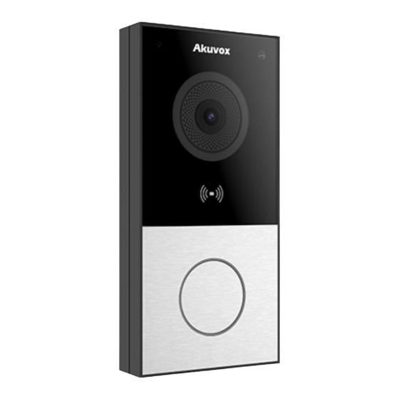
Product Overview
Plastic wall anchor x 4
Wiring cover x 1
7-PIN cable x 1
Wall-mounting template x 1
E12
M3x4 crosshead screw x 4
Torx wrench x 1
6-PIN cable x 1
Diode
x
1
Mic
Photosensitive Sensor
White Light LED
Camera
RF Card Reader(Except E12N)
Call Button
E12
Advertisement
Table of Contents

Related Manuals for Akuvox E12


Summary of Contents for Akuvox E12
- Page 1 Before you being using the device, please check the version you obtained and ensure that the following items are included in the shipped box: Universal Accessories : E12 x 1 Plastic wall anchor x 4 M3x4 crosshead screw x 4...
-
Page 2: Installation Environment
Installation Environment Please do not place device under direct sunlight, it will bring bad effect or be broken with high temperature. If installing the device indoors, please keep device at least 2 meters away from light, and at least 3 meters away from window and door. - Page 3 Connect the wires to the interface of Hang the device on to the two square The installation is completed. hangers on the wall-mounting bracket, the device as needed (for details, then use the Torx wrench attached to refer to “Device Wiring” ). After tighten the bottom of the device with arranging the wires, tighten the two M3x6 Torx head screws.
-
Page 4: Device Wiring
Device Wiring Warning When you connect a device containing a coil, such as a relay or an electromagnetic lock, it is necessary to protect the intercom against voltage peak while switching off the induction load. For this way of protection we recommend a diode 1 A / 200 V (included in the a ccessories) connected antiparallet to the device. -
Page 5: Operation
IP Announcement 1. While E12 starts up normally, hold the Call Button for several seconds after the LED light turns blue, voice system will enter IP announcement mode. 2. In announcement mode, the IP address will be announced periodically. 3. Press Call Button again to the announcement mode. -
Page 6: Notice Information
Information contained in this document is believed to be accurate and reliable at the time of printing. This document is subject to change without notice, any update to this document can be viewed on Akuvox’ s website: http://www.akuvox.com © Copyright 2022 Akuvox Ltd. All rights reserved.
Need help?
Do you have a question about the E12 and is the answer not in the manual?
Questions and answers