Akuvox E16 Series Administrator's Manual
Hide thumbs
Also See for E16 Series:
- Administrator's manual (117 pages) ,
- Manual (105 pages) ,
- Quick manual (9 pages)
Table of Contents
Advertisement
Quick Links
Advertisement
Table of Contents

Related Manuals for Akuvox E16 Series


Summary of Contents for Akuvox E16 Series
- Page 2 Version: 1.0 | Date: Jan.2021...
- Page 3 About This Manual Thank you for choosing Akuvox E16 series door phone. This manual is intended for the administrators who need to properly configure the door phone. This manual applies to 116.30.0.43 version, and it provides all the configurations for the functions and features of E16 series door phones.
- Page 4 Introduction of Icons and Symbols Warning: Caution: Note: Informative information and advice from the efficient use of Tip:...
- Page 5 Related Documentation You are advised to refer to the related documents for more technical information via the link below:...
-
Page 6: Table Of Contents
Table of Contents 1. Product Overview ..................... 1 2. Change Log ......................2 3. Model Specification ................... 3 4. Installation ......................5 5. Introduction to Configuration Menu ............17 6. Access the Device .................... 20 6.1. Access the Device Setting on the device ........21 6.2. - Page 7 7.4.1. Configure Screensaver ............32 7.4.2. Upload Screensaver ............... 34 7.5. Volume & Tone Configuration ............37 7.5.1. Volume Configuration ............37 7.5.2. Upload Open Door Tone ............38 7.5.3. Configure Door Access Prompt Text ......40 8. Network Setting ..................... 42 8.1.
- Page 8 9.4.1. Maximum Call Duration Setting ........61 9.4.2. Maximum Dial Duration Setting ........63 9.4.3. Audio& Video Codec Configuration for SIP Calls ..64 9.4.3.1. Configure Audio Codec ..........65 9.4.3.2. Configure Video Codec ..........66 9.5. Configure DTMF Data Transmission ........... 68 10.
- Page 9 12.1.4. Configure Private PIN Access Mode ......93 12.2. Configure RF Card for Door Unlock ........95 12.2.1. Configure RF Card on the Web Interface ....95 12.2.1.1. Configure RF Card Code Format ......96 12.2.2. Configure Facial Recognition for Door Unlock ..97 12.2.2.1.
- Page 10 13.2. Motion Detection ................122 13.3. Security Notification Setting ........... 122 13.3.1. Email Notification Setting ..........122 13.3.2. FTP Notification setting ..........124 13.3.3. TFTP Notification Setting ..........126 13.4. Web Interface Automatic Log-out ........127 14. Monitor and Image .................. 128 14.1.
- Page 11 18. Backup ......................151 19. Auto-provisioning via Configuration File ........153 19.1. Provisioning Principle ..............153 19.2. Configuration Files for Auto-provisioning ......154 19.3. AutoP Schedule ................156 19.4. DHCP Provisioning Configuration .......... 158 19.5. Static Provisioning Configuration .......... 162 20.
-
Page 12: Product Overview
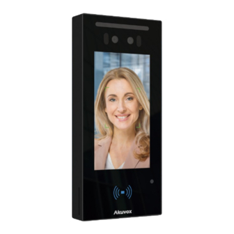
1.Product Overview Akuvox E16 series is an Android-based IP video door phone with a touch screen. It incorporates audio and video communications, access control, and video surveillance. Its finely-tuned Android OS, SmartPlus and AI-based communication technology allow featured customization to better suit your operation habit. E16 series multiple... -
Page 13: Change Log
2.Change Log The change log will be updated here along with the changes in new software version. AKUVOX SMART INTERCOM www.akuvox.com... -
Page 14: Model Specification
3.Model Specification E16C Model & Feature Display 5” IPS Touch Screen √ Button Housing Material Plastic Relay Out Alarm In RS485 √ √ Resolution 1280x720 Brightness 500cd/m AKUVOX SMART INTERCOM www.akuvox.com Card Reader 13.56MHz... - Page 15 Wall √ Mounting Flush √ Mounting Desk Mounting Wall Mounting √ Dimension Wall Mounting √ Dimension POE Stand 5.5W by Power POE Full AKUVOX SMART INTERCOM www.akuvox.com...
-
Page 16: Installation
4.Installation Universal Accessories Accessories Description Quantity Wall-mounting bracket Cable locking plate Back cover Rubber Plug Allen Wrench Torx Wrench Plastic Wall Anchor M3×6 Screw M4×30 Screw Torx Screw AKUVOX SMART INTERCOM www.akuvox.com... - Page 17 M2.5×6 Screw ST4×20 Screw AKUVOX SMART INTERCOM www.akuvox.com...
- Page 18 Digital Temperature Detector Accessories (Optional) No. Accessories Description Quantity Digital Forehead Temperature Detector Digital Wrist Temperature Detector M3x6 Screw 3×10.5 Screw AKUVOX SMART INTERCOM www.akuvox.com...
- Page 19 Use a hand drill with 5mm diameter bit to make two positioning holes with 5mm in depth in the marked positions. Insert two plastic wall anchors into the two drilled holes. Fix the wall-mounting bracket with AKUVOX SMART INTERCOM www.akuvox.com...
- Page 20 With 2x3 Inches Embedded Single-gang Box in the Wall Installation Steps Installation Description Picture Fix the wall-mounting bracket on the single-gang junction box with the two M4x30 screws. Finish the bracket installation. AKUVOX SMART INTERCOM www.akuvox.com...
- Page 21 Note: The positioning holes should be market in the center of the holes. Take off the wall-mounting and drill the four marked positioning holes and the wire holes using 5mm hand drills. Insert four plastic wall anchors into the holes. AKUVOX SMART INTERCOM www.akuvox.com...
- Page 22 Fasten the back cover with four M3x6 screws using the Allen wrench attached with. Hang the device on to the square hanger on the wall mounting bracket, pull AKUVOX SMART INTERCOM www.akuvox.com down device make fall completely on to the square hanger on...
- Page 23 And then select a suitable size rubber plug to push all the cables into the back cover. Fix cable locking plate to the back cover with two M2.5x6 screws using the Allen wrench attached with. AKUVOX SMART INTERCOM www.akuvox.com...
- Page 24 Torx Wrench attached with to tighten the device with the Torx screw. Installation is completed. AKUVOX SMART INTERCOM www.akuvox.com...
- Page 25 Fasten the module on to the nuts on the device ’ s rear cover with two M3X6 screws using the Allen wrench attached with, then Lead the wires from the wall-mount bracket and the module through the square hole on the back AKUVOX SMART INTERCOM www.akuvox.com...
- Page 26 Hang the device on to the square hanger on the wall mounting bracket, pull down device make fall completely on to the square hanger on the wall-mounting bracket, then use the Allen Wrench attached with to tighten the device with two M3x6 screws. AKUVOX SMART INTERCOM www.akuvox.com...
- Page 27 Fasten the back cover with four M2.5x6 screws using the Allen wrench attached with. AKUVOX SMART INTERCOM www.akuvox.com...
-
Page 28: Introduction To Configuration Menu
Access Control: this section includes input type setting, relay setting, door access control in terms private PIN code, Facial recognition, RF card, and BLE setting as well log related configurations such as door log and temperature log. AKUVOX SMART INTERCOM www.akuvox.com... - Page 29 Device: this section concerns LED light setting, ODSP Setting, screen saver setting, sound&volume setting and third-party integration in terms of integration via Wiegand, RS485. Mode selection : 1. Discovery mode: It is a plug and play configuration mode. Akuvox AKUVOX SMART INTERCOM www.akuvox.com...
- Page 30 SmartPlus mode: Akuvox SmartPlus is an all-in-one management system. Akuvox SmartPlus is the mobile service that allows audio, video, remote access control between smart phones and Akuvox intercoms. All configurations in the device will be issued automatically from cloud.
-
Page 31: Access The Device
3. Akuvox PC Manager: Distribute all configuration items in batch on a LAN. 4. IP scanner: it is used to search Akuvox device IP addresses on a LAN. 5. FacePro: Manage face data in batch for the door phone on a LAN. -
Page 32: Access The Device Setting On The Device
To access the device setting, you can do as follows: 1. Long press any where on the initial screen for approximately five seconds to go to project PIN screen. 2. Enter the default PIN code “admin”. 3. press Confirm tab to go to Setting screen. AKUVOX SMART INTERCOM www.akuvox.com... -
Page 33: Access The Device Setting On The Web Interface
You can also enter the device IP address on the web browser in order to log in the device web interface where you can configure and adjust parameter etc. To log in device web interface, you can do as follows: AKUVOX SMART INTERCOM www.akuvox.com... - Page 34 2. Check the device IP address on the device. 3. Enter the IP address on the web browser. 4. Enter the User Name and Password of the device web interface. 5. Click Login tab to log in the web interface. AKUVOX SMART INTERCOM www.akuvox.com...
- Page 35 You can also obtain the device IP address using the Akuvox IP scanner to log in the device web interface. Please refer to the URL below for the IP scanner application: Note Google Chrome browser is strongly recommended.
-
Page 36: Time And Language Setting
7.Time and Language Setting 7.1. Language Setting When you first set up the device, you might need to set the language to your need. You can select the language display the device web interface. AKUVOX SMART INTERCOM www.akuvox.com... -
Page 37: Time Setting
And when your time zone is selected, the device will automatically notify the NTP server of its time zone so that the NTP server can synchronize the time zone setting in your device. AKUVOX SMART INTERCOM www.akuvox.com... - Page 38 4. Enter the NTP server you obtained in the field of the primary and secondary NTP server. 5. Set up the update timing via NTP server. 6. Click the Submit tab for the validation and the Cancel tab for the cancellation. AKUVOX SMART INTERCOM www.akuvox.com...
- Page 39 Secondary Server: enter the secondary NTP server you obtained in the NTP Server field to be used as a backup. Update Interval: set the automatic time update via NTP server. Note: AKUVOX SMART INTERCOM www.akuvox.com When the check box is unticked , the parameters related to...
-
Page 40: Led Setting
To do the configuration, you can do as follows: 1. Click Device > Light > LED of Swiping Card Area 2. Set the parameter and click Submit tab for the validation. AKUVOX SMART INTERCOM www.akuvox.com... -
Page 41: Configure Led White Light Setting
LED White light is used to reinforce the lighting for facial recognition as well as for the QR code access as needed in the dark environment. You can set the white light function properly on the device web interface. AKUVOX SMART INTERCOM www.akuvox.com... - Page 42 And if you select “Off” then the white light will be turned off. Max White Light Value: set the white light value from 1-5, and the default white light value is “3”. The greater value it is, the brighter the light will be. AKUVOX SMART INTERCOM www.akuvox.com...
-
Page 43: Screen Display Configuration
IR LED light should be triggered first before the white light 7.4. Screen Display configuration E16 series door phones allow you to enjoy a variety of screen displays to enrich your visual and operational experience through the customized setting to your preference. - Page 44 “ 30” minutes For example, if you set it as “ 15 seconds” then the device will go into screen saver mode in 15 second when when there is no operation on the device or no one is detected approaching AKUVOX SMART INTERCOM www.akuvox.com...
-
Page 45: Upload Screensaver
5. Set the display time of each individual picture you uploaded in Interval (Sec.) the display time range is from “1-120” seconds. 6. Click Submit tab or Delete tab for the confirmation or the cancellation of the pictures uploaded with the designated ID order AKUVOX SMART INTERCOM www.akuvox.com... - Page 46 You are allowed to upload a maximum of 5 pictures, and each picture will be displayed in rotation according to the ID order with specific time duration (Time Interval ) you set. Please see the picture below: AKUVOX SMART INTERCOM www.akuvox.com...
- Page 47 Note: The pictures uploaded should be in JPG format with 2M AKUVOX SMART INTERCOM www.akuvox.com...
-
Page 48: Volume & Tone Configuration
7.5. Volume & Tone Configuration Volume and tone configuration in E16 door phone refers to the Call volume, the AD volume, key volume and Mic volume and open door tone configuration. Moreover, you can upload the tone you like to enrich your personalized user experience. -
Page 49: Upload Open Door Tone
Mic Volume: set the mic volume from 0-15 according to your need. The default volume is “8”. Speaker Volume: set the speaker volume from 0-15 according to your need. The default volume is “8”. Ring Volume: set the ring volume from 0-15 according to your need. - Page 50 You can upload the Open Door Tone on the device web interface. To upload open door tone, you can do as follows: 1. Click Device >Voice > Open Door Tone Setting 2. Tick the check box in Open Door Tone Setting field to enable the open door time setting.
-
Page 51: Configure Door Access Prompt Text
7.5.3. Configure Door Access Prompt Text You can enable or disable the door access prompt to be shown on the door phone screen for door open failure and success. To do the configuration, you can do as follows: 1. Setting > Door > Open Door Succeeded Text Prompt 2. - Page 52 Parameter set-up: Open Door Success: Tick the check box if you want to see the text prompt after the door open success and vice versa. Open Door Failed: Tick the check box if you want to see the prompt words after the door open failure and vice versa.
-
Page 53: Network Setting
8.Network Setting 8.1. Device Network Connection Setting configure default DHCP mode (Dynamic Host Configuration Protocol) and static IP connection. More over, you can set up IP address, Subnet Mask, Default Gateway, LAN DNS1 & LAN DNS2. To configure the device network connection, you can do as follows: 1. - Page 54 Parameter Set-up: DHCP: select the DHCP mode by checking off the DHCP box. DHCP mode is the default network connection. If the DHCP mode is selected, then the door phone will be assigned by the DHCP server with IP address, subnet mask,default gateway,and DNS server address automatically.
-
Page 55: Device Deployment In Network
IP Address: set up the IP Address if the static IP mode is selected. Subnet Mask: set up the subnet mask according to your actual network environment. Default Gateway: set up the correct gateway default gateway according to the IP address of the default gateway. ... - Page 56 operation mode, address and extension numbers as opposed to other devices for the device control and the convenience of the management. To deploy the device in the network, you can do as follows: 1. Click Network > Advanced > Connect Setting 2.
- Page 57 Server Mode: It is automatically set up according to the actual device connection with a specific server in the network such as SDMC or Cloud and None. None is the default factory setting indicating the device is not in any server type, therefore you are allowed to choose Cloud, SMDC in discovery mode.
-
Page 58: Nat Setting
8.3. NAT Setting In order to speed up the communication between the door phone and the SIP server, you can configure the NAT setting (Network Address Translation) on the web interface. To set up NAT, you can do as follows: 1. -
Page 59: Intercom Call Configuration
RPort: enable the Rport when the SIP server is in WAN (Wide Area Network). 9.Intercom Call Configuration... -
Page 60: Ip Call & Ip Call Configuration
Intercom call in the device can be configured to allow you to perform a variety of customized intercom calls such as IP call and SIP call for different application scenarios. 9.1. IP call & IP Call Configuration IP call can be made directly on the intercom device by entering the IP number on the device. -
Page 61: Ip Call Configuration
Note: You can press Home on the Dial screen if you want to go 9.1.2. IP Call Configuration To configure the IP call on the device web interface, you can do as... - Page 62 follows: 1. Click Intercom > Basic > Direct IP 2. Set up related parameters as needed. 3. Click Submit tab for the validation or Cancel tab for the cancellation. Parameter set-up: Direct IP Call: click “Enable” or “Disable” to turn the direct IP call on or off.
-
Page 63: Sip Call &Sip Call Configuration
9.2.1. SIP Account Registration E16 series door phones support two SIP accounts that can all be registered according to your applications. The SIP account can be configured on the device interface. - Page 64 as follows: 1. Click Account > Basic > SIP Account 2. Set up parameters for the SIP Account. 3. Click Submit tab for the validation and Cancel tab for the cancellation. Parameter Set-up: Status: check to see if the SIP account is registered or not. ...
-
Page 65: Sip Server Configuration
deactivate the registered SIP account. Display Name: configure the name, for example the device’s name to be be shown on the device being called to. Display Label: configure the device label to be shown on the device screen. ... - Page 66 through SIP server between intercom devices. To set up SIP server , you can do as follows : 1. Click Account > Basic > Preferred SIP Server 2. Enter parameters required. 3. Press Submit tab for the validation and Cancel tab for the cancellation.
-
Page 67: Configure Outbound Proxy Server
Alternate SIP Server: enter the backup SIP server IP address or its URL. Port: set up SIP server port for data transmission. Registration Period: set up SIP account registration time pan. SIP re-registration will start automatically if the account registration fails during the registration time span. - Page 68 2. Set up parameters properly. 3. Press Submit for the validation. Parameter Set-up: Enable Outbound: click “Enable” and “Disable” to turn on or turn off the outbound proxy server. Server IP: enter the SIP address of the outbound proxy server. ...
-
Page 69: Configure Data Transmission Type
backup outbound proxy server. 9.2.4. Configure Data Transmission Type SIP message can be transmitted in three data transmission protocols: Datagram Protocol),TCP(Transmission Control (User Protocol),TLS (Transport Layer Security) and DNS-SRV. In the meantime, you can also identify the server from which the data come from. -
Page 70: Call Auto-Answer Configuration
Parameter Set-up: UDP: select “UDP” for unreliable but very efficient transport layer protocol. UDP is the default transport protocol. TCP: select “TCP” for Reliable but less-efficient transport layer protocol. TLS: select “TLS” for Secured and Reliable transport layer protocol. - Page 71 You can define how quick the door phone should response in answering the incoming SIP/IP call automatically by setting up the time related parameters. In addition, you can also define the mode in which the calls are to be answered ( video mode or audio mode) To do the configuration, you can do as follows: 1.
-
Page 72: Call Settings
Parameter Set-up: Auto Answer: turn on the the Auto Answer function by clicking “Enable”. Auto Answer Delay: set up the delay time (from 0-5 sec.) before the call an be answered automatically. For example, if you set the delay time as 1 second, then the call will be answered in 1 second automatically. - Page 73 E16 series door phone allows you to set up the call time duration in receiving the call from the calling device as the caller side might forget to hang up the phone. When the call time duration is reached, the door phone will terminate the call automatically.
-
Page 74: Maximum Dial Duration Setting
9.4.2. Maximum Dial Duration Setting Maximum Dial duration is consisted of Maximum dial-in time duration and the maximum dial-out time. Maximum dial in time refers to the maximum time duration before the door phone hang up the call if the call is not answered by the door phone. In contrary, Maximum dial-out time refers to the maximum time duration before the door phone hang up itself automatically when the call from the door phone is not answered by the intercom device being called to. -
Page 75: Audio& Video Codec Configuration For Sip Calls
Parameter set-up: Dial In Time: enter the dial in time duration for you door phone (ranging from 30-120 sec.) for example, if you set the dial in time duration is 60 second in your door phone, then the door phone will hang up the incoming call automatically if the call is not answered by the door phone in 60 seconds. -
Page 76: Configure Audio Codec
Calls 9.4.3.1. Configure Audio Codec E16 series door phone support four types of Codec (PCMU, PCMA, G729, G722) for encoding and decoding the the audio data during the call session. Each type of Codec vary in terms of the sound quality. -
Page 77: Configure Video Codec
Please refers to the bandwidth consumption and sample rate for the four types of codecs below: Codec Type Bandwidth Sample Rate Consumption PCMA 64 kbit/s 8kHZ PCMU 64 kbit/s 8kHZ G729 8 kbit/s 8kHZ 9.4.3.2. Configure Video Codec This series support H.264 codec that provides a better video quality at much lower bit rate with different video quality and payload. - Page 78 2. Tick the H.264 Codec name check box. 3. Set up parameters according to your need. 4. Click Submit tab for the validation or Cancel tab for the Cancellation. Parameter set-up: Name: Check to select the H264 video codec format for the door phone video stream.
-
Page 79: Configure Dtmf Data Transmission
Payload: select the payload type (ranging from 90-118) to configure the audio codec payload. The pay load between the door phone and the corresponding intercom device should be identical. The default payload is 104. 9.5. Configure DTMF Data Transmission In order to achieve the door access via DTMF code or some other applications, you are required to properly configure DTMF in order to establish a DTMF-based data transmission between the door phone... - Page 80 Parameter set-up: Mode: select DTMF mode among five options: “Inband”, “RFC2833”, “Info+Inband” and “Info+RFC2833” based on the specific DTMF transmission type of the third party device to be matched with as the party for receiving signal data. How to Notify DTMF:select among four types: “Disable” “ DTMF” “DTMF-Relay”...
-
Page 81: Relay Switch Setting
10. Relay Switch Setting 10.1. Relay Switch Setting You can configure the relay switch(es) and DTMF for the door access on the web interface. To do the configuration, please do as follows: 1. Click Access Control > Relay > Relay 2. - Page 82 Parameter Set-up: Trigger Delay (Sec): set the relay trigger delay timing (Ranging from 1-10 Sec.) For example, if you set the delay time as “5” sec. then the relay will not triggered until 5 seconds after you press “unlock “ tab. ...
- Page 83 digit DTMF code or 2-digit DTMF code etc., according to your need. 1-digt DTMF : set the 1-digt DTMF code within range from ( 0-9 and *,#). 2~4 Digits DTMF: set the DTMF code according to the DMTP Option setting.
-
Page 84: Web Relay Setting
Note: If DTMF mode is set as “1 Digit DTMF” , you cannot edit DTMF code in 2~4 Digits DTMF field. And if you set DTMF 10.2. Web Relay Setting In additional to the relay that is connected to the door phone, you can also control the door access using the network-based web relay on the device and on the device web interface. - Page 85 To do the configuration , you can do as follows: 1. Click Access Control > Web Relay 2. Enter the parameters properly. 3. Go to the “Web Relay Action Setting” below in the same interface. 4. Configure the parameter properly. 5.
- Page 86 Type: select among three options “Disabled” “WebRelay” and “Both”. Select “WebRelay” to enable the web relay. Select “Disable” to disable the web relay. Select “Both” to enable both local relay and web relay. IP Address: enter the we relay IP address provided by the web relay manufacturer.
- Page 87 relay automatically. Web Relay Extension: enter the relay extension information, which can be a SIP Account user name of an intercom device such as an indoor monitor, so that the specific action command will be sent when unlock is performed on the intercom device, while this setting is optional.
-
Page 88: Configure Web Relay On The Device
corresponding location in the Web Relay field. 5. Click Submit tab for the validation. 10.2.2. Configure Web Relay on the Device You can also assign a specific web relay to a resident for the door access based on order of the the web relay set up on the web interface. To do so , you can do as follows: 1. - Page 89 5. Press the Save tab on the Add User screen for the validation...
-
Page 90: Door Access Schedule Management
Door Access Schedule Management You are required to configure and make schedule for the user-based door access via RF card, Private PIN and Facial recognition. -
Page 91: Configure Door Access Schedule
11.1. Configure Door Access Schedule You can create door access schedules so that they can be later conveniently applied to the door access control intended for individual user or a group of users created. More over, you can edit your door access schedule if needed. - Page 92 3. Enter the schedule name. 4. Set up the daily time schedule for the validity of the door access. 5. Click Add tab for the validation and Reset tab to clear the setting. To create a weekly schedule, you can do as follows: 1.
- Page 93 To create a longer period schedule, you can do as follows: 1. Click Schedule Type field to select “Normal” Type. 2. Repeat the setting in the identical way as you do for the “ Weekly” schedule. 3. Set the time period specifying year, month and date. 4.
-
Page 94: Import And Export Door Access Schedule
11.1.2. Import and Export Door Access Schedule In addition to creating door access schedule separately, you can also conveniently import or export the schedules in order to maximize your door access schedule management efficiency. To import and export the schedule, you can do as follows: 1. -
Page 95: Edit The Door Access Schedule
Note: It only supports .xml format file for importing and exporting 11.1.3. Edit the Door Access Schedule If you want to edit or delete your door access schedule you created, you can edit or delete the configured schedule separately or in batch on the web interface. -
Page 96: Door Unlock Configuration
12. Door Unlock Configuration E16 series door phone offer you three types of door access via PIN code, RF card and Facial recognition. You can configure them on the device and web interface. More over, you can import or exporting the... -
Page 97: Configure Pin Code For Door Unlock
12.1. Configure PIN Code for Door Unlock You can create and modify both public PIN code and private PIN code for the door access on E16 series door phones. 12.1.1. Configur Public PIN code You can configure and modify a total of 3 sets of separate PIN codes on the device web interface. - Page 98 Note: Public PIN code will not valid until the function is turned on. Note: APT+PIN can only be applicable when the device is added to...
-
Page 99: Configure Private Pin Code On The Device
12.1.2. Configure Private PIN Code on the Device You can configure door access by Private PIN code on the device by entering the user’s name and the PIN code for the door access. To configure private PIN code , you can do as follows: 1. -
Page 100: Configure Private Pin Code On The Web Interface
12.1.3. Configure Private PIN Code on the Web Interface... - Page 101 On the web interface, you can not only set up PIN code, but also set and select the door access schedule that you created for the validity of the PIN Code access during a certain time span you scheduled. In addition, you can set the limit for the total number of valid PIN code door access.
- Page 102 To select door access Schedule for Private PIN Code door access, you can do as follows: 1. Go to Access Setting section in the same interface page 2. Set up PIN code validity time in the Validity Term field. 3. Set the limit for the total number of PIN code door access. 4.
- Page 103 Parameter Set-up: Validity Term: select validity term among three options: “Always”, “ Schedule” and “ Never”. if you select “Always”, then the door access via PIN code will always be valid with no restriction. If you select “ Schedule”, then you are required to select among the created schedule for user-based PIN code access.
-
Page 104: Configure Private Pin Access Mode
This step is applicable to door access by RF card and facial 12.1.4. Configure Private PIN Access Mode E16 series door phones offer you two types of access modes for private PIN code access, namely “ PIN” and “ APT#+PIN”. - Page 105 Parameter Set-up: Authorization Mode: select access mode between “ PIN” and “APT#+PIN”. if you select “PIN” then you are only required to enter PIN code directly for the door access,while if you select “ APT#+PIN”, then you are required to enter the Apartment Number first before entering your PIN code for the door access.
-
Page 106: Configure Rf Card For Door Unlock
12.2. Configure RF Card for Door Unlock 12.2.1. Configure RF Card on the Web Interface To configure RF card , you can do as follows: 1. Click Access Control > User 2. Click the Add tab. 3. Go to User Basic section. 4. -
Page 107: Configure Rf Card Code Format
Note: RF card with 13.56 MHz and 125 KHz can be applicable to 12.2.1.1. Configure RF Card Code Format If you want to integrate with the third party intercom system in terms of RF card door access, you can change the RF card code format to be identical with that applied in the third party system. -
Page 108: Configure Facial Recognition For Door Unlock
Parameter Set-up: IC-Card Display Mode: select the card format for the ID Card for the door access among five format options: 8H10D; 6H3D5D(W26); 6H8D; 8HN; 8HR. The card code format is 8HN by default in the door phone. 12.2.2. Configure Facial Recognition for Door Unlock... -
Page 109: Configure Facial Recognition On The Device
12.2.2.1. Configure Facial Recognition on the Device To configure the facial recognition, you can do as follows: You can configure door access by facial recognition on the device by entering the user’s name and register your facial ID on the device for the door access. -
Page 110: Configure Facial Recognition On Web Interface99
6. Press Save tab on the bottom to save the facial registration. 12.2.2.2. Configure Facial Recognition Interface... - Page 111 To configure PIN code , you can do as follows: 7. Click Access Control > User 1. Click the Add tab. 2. Go to User Basic section. 3. Enter the user’s name and floor number 4. Click Select File tab to upload the picture from PC for facial recognition.
-
Page 112: Configure Door Access Using Configured Files
Note: 12.3. Configure Door Access Using Configured Files. E16 series door phones allow you to speedily configure user(s)-specific door access in batch by importing the configured all-in-one door access control files incorporating user information, door access type,... - Page 113 door access schedule etc., thus all the door access setting can be done at one stop, saving your time and effort from configuring the door access for users separately when users are large in number. To import the configured door access files, you can do as follows: 1.
-
Page 114: Editing The User(S)-Specific Door Access Data
Note: Configured file for facial recognition and the other types of 12.4. Editing the User(s)-specific door access data You can search user(s)-specific door access and edit the door access data on the web interface. To search and edit the user data, you can do as follows: 1. -
Page 115: Unlock By Qr Code
2. Enter the search information in the Search field and press Reset tab if you want to clear the information entered. 3. Click Edit tab to add the user data. 4. Tick the check box of the specific user if you want to delete the user or ticket the the check box by the the Index to delete all the user data. -
Page 116: Unlock By Bluetooth
12.4.2. Unlock by Bluetooth You can also gain the door access by mobile phone with Bluetooth which is used together with Akuvox SmartPlus. You can shake the mobile phone closer to the door phone for the door access. 1. Click Access Control > BLE > BLE... - Page 117 2. Set up parameter according to your need. 3. Click on Submit tab for the validation and Cancel tab for the cancellation. Parameter Set-up: Enabled: enable or disable the Bluetooth function. Bluetooth is turned off by default. Rssi Threshold: select signal...
-
Page 118: Unlock By Http Command On Web Browser
12.4.3. Unlock by HTTP Command on Web Browser You can unlock the door remotely without approaching the device physically for the door access by typing in the created the HTTP command (URL) on the web browser to trigger the relay when you are not available by the door for the door access. - Page 119 Parameter Set-up: Enable: enable the HTTP command unlock function by clicking on Enable field. User Name: enter the user name of the device web interface, for example “Admin”. Password: enter the password for the HTTP command. For example : “12345”.
-
Page 120: Unlock By Exit Button By The Door
Note: DoorNum in the HTTP command above refers to the relay 12.4.4. Unlock by Exit Button by the Door When you need to open the door from inside using the exit button installed by the door, you can configure the door phone Input to trigger the relay for the door access. - Page 121 Parameter set-up: Trigger Electrical Level: select the trigger electrical level options between “High” and “Low” according the actual operation on the Execute Relay: set up relays to be triggered by the input. Door Status: display the status of input signal.
-
Page 122: Unlock By Reception Tab
12.4.5. Unlock by Reception Tab In the device home screen, E16 series door phone provide residents and visitors a quick door access by pressing the Reception tab on the bottom of the home screen. To do the configuration, you can do as follows: 1. - Page 123 Parameter Set-up: Reception Enabled: Tick the check box to enable the function. Name: enter the name for the Reception icon on the home screen. Number: enter the SIP/IP number to be called to after pressing the Reception icon for the door access.
-
Page 124: Unlock By Dtmf Code
12.4.6. Unlock by DTMF Code DTMF codes can be configured on the door phone web interface and set up identical DTMF code on the corresponding intercom devices such as indoor monitor, which allows residents to enter the DTMF code on the soft keypad or press DTMF code attached unlock tab on the screen to unlock the door for visitors etc., during a call. - Page 125 Type: select DTMF type among five options: “ Inband”, “ RFC2833”, “ Info+Inband” and “Info+RFC2833” according to you need. How to Notify DTMF: select among four options: “Disable” “ DTMF” “DTMF-Relay” “Telephone-Event” according to your need. DTMF Payload: select the payload 96-127 for data transmission identification.
-
Page 126: Optional
12.4.7. Body Temperature Measurement for Door Access(Optional) E16 series provide you with an optional body temperature measurement function designed to be applied in the situation where the measurement becomes necessary for the safety of the residents and visitors etc. Residents and visitors are required to go through temperature measurement along with optional mask detection check before they are allowed for the door access. - Page 127 1. Click Access Control > Body Temperature > Measuring Body Temperature 2. Set up parameters properly. 3. Set the schedule for the validity of the body temperature measurement. 4. Click on Submit tab for the validation and Cancel tab for the cancellation.
- Page 128 be installed with digital forehead temperature detector therefore you can are required to set the mode properly according to your application. Mask Detection: select “Enable” or” Disable” to turn on or turn off the mask detection. When enabled, the device will check if the visitor is wearing a mask or not while reminding the visitor with the announcement “Please wear a mask”...
-
Page 129: Ambient Temperature Configuration
Action to Execute: check the box to enable or disable the SIP/IP Call. If you want to be notified via SIP/IP call when abnormal temperature and low temperature is detected. SIP/IP Call Number: enter the SIP or IP call for the notification. The field will appear for you to fill in SIP/IP numbers when you check the box in the Action to Execute field. - Page 130 1. Click Access Control > Body Temperature > Ambient Temperature Setting 2. Set up parameters properly. 3. Click Submit tab for the validation or Cancel tab for the cancellation. Parameter Set-up: Start Time/End Time: select the start time and end time temperature by referring to the actual temperature measured at the time segments ranging from 10- 40℃degree Celsius.
-
Page 131: Security
each of the time segments will be six hours (24 hours a day), while the end time of one segment should be the start time of the next time segment. You can divide the time segments according to your need. ... - Page 132 To set up the temper alarm , you can do as follows: 1. Click Security > Basic > Temper Alarm 2. Tick the check box to enable the temper alarm function. Parameter Set-up: Enable: tick the check box to enable the temper alarm function. When the temper alarm goes off , you can press the Disarm tab beside the check box to clear the alarm.
-
Page 133: Motion Detection
Note: The round rubber button at the back of the device must be in 13.2. Motion Detection 13.3. Security Notification Setting 13.3.1. Email Notification Setting If you want to receive the security notification via email, you can configure the Email notification on the web interface properly. To do the configuration, you can do as follows: 1. - Page 134 2. Set up parameters properly according to your need. 3. Click Submit tab for validation and Cancel tab for cancellation. Parameter set-up: Sender’s Email Name: enter the name of the email sender. Sender's email address: enter the sender’s email address from which the email notification will be sent out.
-
Page 135: Ftp Notification Setting
Receiver's email address: enter the receiver’s email address. Receiver’s Email Name: enter the the name of the email receiver. SMTP server address:enter the SMTP server address of the sender. Port: enter the port number from which the email is sent out. ... - Page 136 If you want to receive the security notification via FTP, you can configure the FTP notification on the web interface properly. To do the configuration, you can do as follows: 1. Click k Setting > Action > FTP Notification 2. Set up parameters properly according to your need. 3.
-
Page 137: Tftp Notification Setting
FTP User Name: enter the FTP server user name. FTP Password: enter the FTP server password. FTP Path: enter the folder name you created in FTP server. 13.3.3. TFTP Notification Setting If you want to receive the security notification via TFTP, you can configure the FTP notification on the web interface properly. -
Page 138: Web Interface Automatic Log-Out
Parameter set-up: TFTP Server: enter the address (URL) of the TFTP server for the FTP notification 13.4. Web Interface Automatic Log-out You can set up the web interface automatic log-out timing, requiring re-login by entering the user name and the passwords for the security purpose or for the convenience of operation. -
Page 139: Monitor And Image
14. Monitor and Image 14.1. Mjpeg Image Capturing E16 series allow you to capture the Mjpeg format monitoring image if needed. You can enable the Mjpeg function and set the image quality on the web interface. To do the configuration, you can do as follows: 1. - Page 140 cancellation. Parameter Set-up: Enabled: Tick the check box to enable or disable the Mjpeg service. Image Quality: select the quality for the image capturing among seven options: QCIF, QVGA, CIF, VGA, 4CIF, 720P, 1080P After the Mjpeg service is enabled, you can capture the image from the door phone using following three types of URL format: ...
-
Page 141: Live Stream
2. Ppress Enter key in your keyboard to capture the image. 14.2. Live Stream If you want to check the real-time video from the E16 series door phone, you can go to the the device web interface to obtain the real-time video or you can also enter the correct URL on the we browser to obtain it directly. - Page 142 1. Click Surveillance > Live Stream 2. Check the real time video on the web interface. To check the real time video using URL, you can do as follows: 1. Enter the correct URL (http://IP_address:8080/video.cgi) on the web browser if you want to obtain the real-time video directly with going to the web interface.
-
Page 143: Rtsp Stream Monitoring
14.3. RTSP Stream Monitoring E16 series door phone support RTSP stream that allows intercom devices such as indoor monitor or the monitoring unit from the third party to monitor or obtain the the real time audio/ video (RTSP stream) from the door phone using the correct URL. - Page 144 Authorization, authentication and password etc., before you are able to use the function. To do the configuration, you can do as follows: 1. Click Surveillance > RTSP > RTSP Basic 2. Set up parameters properly. 3. Click Submit tab for validation and Cancel tab for cancellation. Parameter Set-up: ...
-
Page 145: Rtsp Stream Setting
Authorization Enabled: Tick the check box to enable the RTSP authorization. If you enable the RTSP Authorization, you are required to enter RTSP Authentication Type, RTSP Username, RTSP Password on the intercom device such as indoor monitor for authorization. ... - Page 146 interface. To configure the parameters, please do as follows: 1. Click Surveillance > RTSP > H.264 Video Parameters 2. Set up video parameters according to your need. 3. Click Submit tab for validation and Cancel tab for cancellation. Parameter Set-up: ...
- Page 147 2nd Video Bitrate: select video bit-rate among the six options for the second video stream channel. While the second video stream channel is “512 kpbs” by default. Note: E16 series supports two video stream channels for H.264 codec...
-
Page 148: Onvif
14.4. ONVIF Real-time video from the E16 series door phone camera can be searched and obtained by the Akuvox indoor monitor or by the third party devices such as NVR (Network Video Recorder) you can configure the ONVIF function in the door phone so that other device will be able to see the video from the door phone. - Page 149 1. Click Intercom > ONVIF 2. Set up parameters properly. 3. Click Submit tab for validation and Cancel tab for cancellation. Parameter Set-up: Discoverable: Tick the check box to turn on the the ONVIF mode. If you select video from the door phone camera can be searched by other devices.
- Page 150 default. After the setting is complete, you can enter the ONVIF URL on the third party device to view the video stream. For example: http://IP address:80/onvif/device_service Note:...
-
Page 151: Logs
15. Logs 15.1. Call Logs If you want to check on the calls inclusive of the dial-out calls , received calls and missed calls in a certain period of time, you can check and search the call log on the device web interface and export the call log from the device if needed. -
Page 152: Door Logs
2. Click Call history field to select specific type of call log. 3. Click Export tab if you want to export the call log. 4. Check the specific call log check box and click Delete tab to delete. 5. Click Delete all tab if you want to delete all of the call logs. Parameter Set-up: ... - Page 153 and check the door logs on the device web interface. To access the door logs , you can do as follows: 1. Click Access > Door log 2. Tick the the check box of Save Door Log Enabled if you want to save the log.
-
Page 154: Temperature Log
Parameter set-up: Save Door Log Enabled: Tick the check box to turn on or turn off the door log function. Status: select between “Success” and “Failed” options to search for successful door accesses or Failed door accesses. Time: select the specific time select the specific time span of the door logs you want to search, check or export. - Page 155 To check temperature log, you can do as follows: 1. Click Access Control > Temperature Log 2. Click Status field to select the range and category of temperature log check among four options:“All”, “Normal”, “Abnormal”, “Low Temperature”. 3. Click Filter tab to see the specific category of temperature log selected.
-
Page 156: Debug
16. Debug 16.1. System Log for Debugging System log in the door phone can be used for debugging purpose. If you want to export the system out to a local PC or to a remote server for debugging , you can set up the function on the web interface. To do the configuration, you can do as follows: 1. - Page 157 Parameter Set-up: LogLevel: select log levels from 1 to 7 levels. You will be instructed by Akuvox technical staff about the specific log level to be entered for debugging purpose. The default log level is “3”, the higher the level is “5”, the more complete the log is “7”.
-
Page 158: Pcap For Debugging
Akuvox technical support. 16.2. PCAP for Debugging PCAP in E16 series door phone is used to capture the data package going in and out of the devices for debugging and troubleshooting purpose. You can set up the PCAP on the device web interface properly before using it. - Page 159 tab. Parameter set-up: Specific Port: select the specific ports from 1-65535 so that only the data packet from the specific port can be captured. You can leave the field blank by default. PCAP: click Start tab and Stop tab to capture the a certain range of data packets before clicking Export tab to export the data packets to you Local PC.
- Page 160 1MB.
-
Page 161: Firmware Upgrade
17. Firmware Upgrade Firmwares of different versions for E16 series door phone can be upgraded on the device web interface. To upgrade the firmware, you can do as follows:... -
Page 162: Backup
1. Click Upgrade > Basic 2. Select firmware files from your local PC. 3. Press Submit tab for the validation and Cancel tab for the cancellation. Note: 18. Backup... - Page 163 Configuration files can be imported to or exported out of the device to your local PC on the device web interface if needed. To do so , you can do as follows: 1. Click Upgrade > Advanced > Others 2. Click Select File to select the file from your local PC. 3.
-
Page 164: Auto-Provisioning Via Configuration File
19. Auto-provisioning via Configuration File Configurations and upgrading on E16 series door phone can be done on the web interface via one-time auto-provisioning and scheduled auto- provisioning via configuration files, thus saving you from setting up configuration needed one by one manually on the door phone. -
Page 165: Configuration Files For Auto-Provisioning
DHCP, PNP, TFTP, FTP, HTTPS are the protocols used by the Akuvox intercom devices to access the URL of the address of the third party server which stores configuration files and firmwares, which will then be used to to update the firmware and the corresponding parameters on the door phone. - Page 166 Configuration files have two formats for the auto-provisioning. one is the general configuration files used for the general provisioning and other one is the MAC-based configuration provisioning. The difference between the two types of configuration files is shown as below: ...
-
Page 167: Autop Schedule
If a server has these two types of configuration files, then IP devices will first access the general configuration files before 19.3. AutoP Schedule Akuvox provides you with different Autop methods that enable the door phone to perform provisioning for itself in a specific time according to your schedule. - Page 168 1. Click Upgrade > Advanced > Automatic Autop 2. Set up mode and schedule according to your need. 3. Click Submit tab for the validation and Cancel tab for the cancellation. Parameter Set-up: Power On: select “Power on”, if you want the device to perform Autop every time it boots up.
-
Page 169: Dhcp Provisioning Configuration
Power On + Repeatedly: select “Power On + Repeatedly” if you want to combine Power On Mode and Repeatedly mode that will enable the device to perform Autop every time it boots up or according to the schedule you set up. ... - Page 170 1. Click Upgrade > Advanced > Automatic Autop 2. Click Export tab in Export Autop Template to export Autop template. 3. Set up DHCP Option on DHCP server.
- Page 171 Note: The custom Option type must be a string. The value is the URL 4. Rename the AutoP config template. 5. Select general provisioning configuration file for the device in-batch provisioning or the MAC-based configuration file for the specific device provisioning. 6.
- Page 172 Parameter set-up: Custom Option: enter the DHCP code that matched with corresponding URL so that device will find the configuration file server for the configuration or upgrading. DHCP Option 66: If none of the above is set, the device will automatically use DHCP Option 66 for getting the upgrade server URL.
-
Page 173: Static Provisioning Configuration
Note: The general configuration file for the in-batch provisioning is with the format “r0000000000xx.cfg” taking E16 as an example “r000000000016.cfg ( 10 “zeros” in total while the 19.5. Static Provisioning Configuration You can manually set up a specific server URL for downloading the firmware or configuration file. - Page 174 2. Click Export tab in Export Autop Template to export Autop template. 3. Rename the AutoP config template. 4. Select general provisioning configuration file for the device in-batch provisioning or the MAC-based configuration file for the specific device provisioning. (for example: r000000000016 for E16 door phone and r000000000115 for C315 in door monitor) 5.
- Page 175 Parameter set-up: URL: set up tftp , http , https , ftp server address for the provisioning. User Name: set up a user name if the server needs an user name to be accessed to otherwise leave it blank. ...
- Page 176 MAC-based auto provisioning configuration file. Note: Note: Server Address format: TFTP: tftp://192.168.0.19/ FTP: ftp://192.168.0.19/ (allows anonymous login) ftp://username:password@192.168.0.19/(requires a user name and password) Tip: Akuvox do not provide user specified server. Please prepare TFTP/FTP/HTTP/HTTPS server by yourself.
-
Page 177: Integration With Third Party Device
20. Integration with Third Party Device... -
Page 178: Integration Via Wiegand
20.1. Integration via Wiegand If you want to integrate the E16 series door phone with the third party devices via Wiegand, you can configure the Wiegand on the web interface. 1. Click Device > Wiegand > Wiegand 2. Set up parameters according to your need. - Page 179 8H10D; 6H3D5D; 6H8D; 8HN; 8HR; RAW. Wiegand Card Reader Mode: set the wiegand data transmission format among three options: “ Wiegand 26”, “ Wiegand 34”, “ Wiegand 58”. The transmission format should be identical between the door phone and the device to be integrated. ...
-
Page 180: Integration Via Rs485
according to the established data transmission format. 20.2. Integration via RS485 RS485 Integration mode should be configured properly on the door phone’s web interface before you can implement the integration between the door phone and the third party devices. To do the configuration, you can do as follows: 1. - Page 181 “ None” ,” OSDP”, the detail for the two options will be provided in the following chart. NO. Integration Description Mode None If you select “None” then the RS485 integration will be disabled. OSDP If you Select “OSDP” Mode, then the integration communication between the E16 series door phone and the third...
-
Page 182: Osdp Setting
20.3. OSDP Setting If you choose OSDP integration mode, you can not only check for OSDP status but also obtain the authentication from the third party devices for various applications such as door access etc. To do the configuration, please do as follows: 1. - Page 183 Parameter Set-up: Connect Status: indicate OSDP based communication status. Send by: select in what way you want to send out the card number among three options: “OSDP”, “Wiegand” and “ None”. if you select “OSDP” then the card number will be sent out to the third party devices via RS485.
-
Page 184: Password Modification
21. Password Modification On the device web interface, you can set and change both the project... - Page 185 PIN Code for accessing the device setting and password for accessing the web interface. In addition, you can also select the user role when setting passwords. To set and change the web interface passwords, you can do as follows: 1. Click Security > Basic > Web Password Modify 2.
-
Page 186: System Reboot&Reset
3. Click Submit tab for the validation and Cancel tab for the cancellation. 22. System Reboot&Reset 22.1. Reboot If you want to restart the device, you can operate it on the device web interface as well. More over, you can set up schedule for the device to be restarted. - Page 187 1. Click Upgrade > Basic 2. Click on Submit tab for restarting the device. To set up the device restart schedule, you can do as follows: 1. Click Upgrade > Advanced > Reboot Schedule 2. Enable the scheduled Reboot mode. 3.
-
Page 188: Reset
22.2. Reset If you want to reset the device system to the factory setting, you can it on the web interface. To reset to the factory setting, you can do as follows: 1. Click Upgrade > Basic 2. Click on Submit tab for Reset to Factory Setting. -
Page 189: Abbreviations
23. Abbreviations ACS: Auto Configuration Server Auto: Automatically AEC: Configurable Acoustic and Line Echo Cancelers ACD: Automatic Call Distribution Autop: Automatical Provisioning AES: Advanced Encryption Standard BLF: Busy Lamp Field COM: Common CPE: Customer Premise Equipment CWMP: CPE WAN Management Protocol DTMF: Dual Tone Multi-Frequency DHCP: Dynamic Host Configuration Protocol DNS: Domain Name System... - Page 191 PCMA: Pulse Code Modulation A-Law PCMU: Pulse Code Modulation µ-Law PCAP: Packet Capture PNP: Plug and Play RFID: Radio Frequency Identification RTP: Real-time Transport Protocol RTSP: Real Time Streaming Protocol MPEG: Moving Picture Experts Group MWI: Message Waiting Indicator NO: Normal Opened NC: Normal Connected NTP: Network Time Protocol NAT: Network Address Translation...
-
Page 193: Faq
24. FAQ Q1: How to obtain IP address of R2X A1: ✔ For devices with single button - E21/ R20/ R23/ R26: While E21/ R20/ R23/ R26 power up normally, hold the call button for 5 seconds after the statue LED turns blue and it will enter into IP announcement mode. - Page 194 Using Akuvox IP Scanner to search Akuvox devices in the same LAN network. Q2: Do Akuvox devices support opus codec? A2: For now, only Akuvox Android video IP phone R48G can support Opus audio codec. Q3: What is the supported temperature range for akuvox doorphone? A3: R20/E21/R26/R23/Standard R27/Standard R29 -- 14°...
- Page 195 3. After you export , you need to unzip the .tgz folder , then make the unziped folrder into .zip again. Q55: Which version of ONVIF does R20 and R29 support? A55: Onvif 18.04 profiles Q6: Do door phones support these card types? Prox, Legacy iClass,iClassSE,HID Mifare, HID DESFire,HID SEOS A6: Sorry, they are not supported.
- Page 196 Hardware version 2 Firmware Version The firmware is different between hardware version1 and hardware version 2. Go to Web-Status -Firmware Version.
- Page 197 20.X.X.X is hardware version 1. 220.X.X.X is hardware version 2. Hardware version The firmware is different between hardware version1 and hardware version 2. Go to Web-Status -Firmware Version. If the hardware version is 220.x, then the device is hardware version...
-
Page 198: Contact Us
25. Contact Us For more information about the product, please visit us at www.akuvox.com or feel free to contact us by Sales email: sales@akuvox.com Technical support email: support@akuvox.com Telephone: +86-592-2133061 ext.7694/8162 We highly appreciate your feedback about our products.
Need help?
Do you have a question about the E16 Series and is the answer not in the manual?
Questions and answers