Advertisement
Quick Links
Advertisement

Related Manuals for CLEAR DESIGN BOOST PRO BP-1


Summary of Contents for CLEAR DESIGN BOOST PRO BP-1
- Page 1 BP–1 BOOST PRO FACING INSTALLATION GUIDE *General Guide | See Master Plan...
- Page 3 48" POWER PARTS LIST CODE DESCRIPTION BPROTPB Module Mounting Plate (Short) Power Module Bracket Power Beam PRODB Double Receptacle Block PROR Receptacles PROJ Jumper...
- Page 4 1 | ATTACH RECEPTACLE TO MOUNTING PLATE Place receptacle on top of mounting plate. Slide brackets over receptacle and secure with provided screws. Note: Do not over torque screws. 2 | ASSEMBLE POWER BEAM Slide inner beam inside of the outer beam and adjust until at least 2 power slots are visible on the inner beam.
- Page 5 3 | CONNECT JUMPER TO RECEPTACLE Connect the thicker end of the jumper to the double block where the greater jog is located. Greater Lesser...
- Page 6 4 | INSERT POWER INTO BEAM While having the mounting module slightly tilted, insert and guide the jumper through the opposite end of the beam. Pull the jumper out from the other end. Connect the mounting plate to the power beam using 4 screws. Transparency View of Jumper Inside Beam...
- Page 7 54"-72" POWER PARTS LIST 54"-72" CODE DESCRIPTION BPROTPB Module Mounting Plate (Long) Power Module Bracket Power Beam PRODB Double Receptacle Block PROSB Single Receptacle Block PROBC In-line Connector PROR Receptacles PROJ Jumper...
- Page 8 1 | ATTACH RECEPTACLE TO MOUNTING PLATE Place receptacle on top of mounting plate. Slide brackets over receptacle and secure with provided screws. Note: Do not over torque screws. 2 | ASSEMBLE POWER BEAM Slide inner beam inside of the outer beam and adjust until at least 2 power slots are visible on the inner beam.
- Page 9 3 | CONNECT JUMPER TO RECEPTACLE Before securing to power beam, secure jumper(s) to receptacle. Note: Jumper connects to the single block.
- Page 10 4 | INSERT POWER INTO BEAM While having the mounting module slightly tilted, insert and guide the jumper through the opposite end of the beam. Pull the jumper out from the other end. Connect the mounting plate to the power beam using 4 screws. Transparency View of Jumper Inside Beam...
- Page 11 PARTS LIST CODE DESCRIPTION BPROF Adjustable Leg Surface Attachment Bracket Surface Support Bracket Width Adjusting Bracket BPROCB Cross Beam with Cover BPROBRG Jumper Box BPROTPB Data Beam Bridge Power Beam with Assembly Data Beam Set Laminate Surfaces Note: Parts list if for a Pod of 2, additional parts will be needed for larger pods.
- Page 12 1 | SECURE CROSS BEAM Remove cross beam cover and line up pre-drilled holes on inside of beam with mounting plate of leg. Connect the cross beam to each leg using 4 screws. You may need a right angle drill attachment. Repeat step for other set of legs.
- Page 13 3 | ATTACH CROSS BEAM COVERS Align beam covers and slide down and over cross beam. Using 3 screws, secure cover to cross beam from the bottom of the beam. 4 | PLACE SURFACE BRACKET ON FRAME Expand surface brackets so that they align flush with end of the leg cap, being sure all pre-drilled holes are aligned.
- Page 14 5 | SECURE SURFACE AND ARM BRACKETS Align pre-drilled holes of surface and arm bracket to BOOST Pro frame and secure with 4 screws each. 6 | SET WORKSTATION LENGTH Measure from outer edges of legs to determine proper workstation length.
- Page 15 7 | SET POWER BEAM WIDTH Once length of workstation is determined, insert and secure set screws to underside of beam and tighten to secure. Note: Use 2 set screws with 48" workstations and 4 set screws for all other widths. 8 | REMOVE DATA PLATE COVER Secure each side of the power beam to the cross beams using 4 screws.
- Page 16 9 | ASSEMBLE DATA TRAY Slide the inner beam into the grooves of the outer beam and place onto the underside of the power beam. Adjust width as needed and secure.
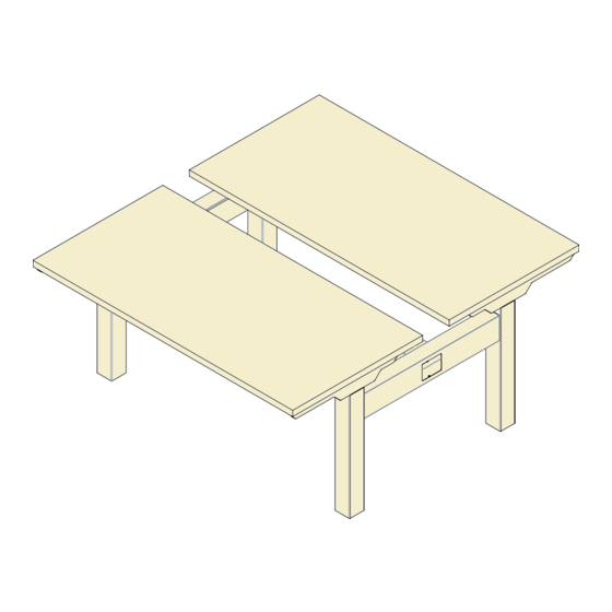
- Page 17 10.1 | PLACE & MEASURE FOR 24" DEEP SURFACE 2 ” 10.2 | PLACE & MEASURE FOR 30" DEEP SURFACE 4 ”...
- Page 18 11 | ATTACH SURFACES Using wood screws provided, secure surfaces to frame.
- Page 19 12 | SECURE AND CONNECT CONTROL BOX Place control box inside of the center beam and secure with 2 wood screws. Connect the leg wires to the control box. 13 | SECURE HANDSET AND CONNECT Connect handset cable to control box. Align front of handset with surface edge and secure with 3 wood screws.
- Page 20 14 | POWER UP AND INITIALIZE Connect cord to power source then press and hold simultaneously for 5 seconds until both leg columns are in lowest position. Desk will slightly rise, lower again, and then stop. Release buttons. The system is now operational.
- Page 21 15 | ALIGN AND CONNECT WORKSTATIONS Pass jumper through bridge extension. Then, insert the extension into the open slot of power bridge on first workstation. Align second workstation, connect jumper, and push workstations together. Both ends of bridge extension should sit inside the power bridge. Insert the data bridge in between the two systems.
- Page 22 210.648.2095 | mycleardesign.com © 2021 Clear Design. All rights reserved.
Need help?
Do you have a question about the BOOST PRO BP-1 and is the answer not in the manual?
Questions and answers
How to Install a Power Pole for This Material