
Related Manuals for CLEAR DESIGN BOOST PRO BP-1


Summary of Contents for CLEAR DESIGN BOOST PRO BP-1
- Page 1 BP-1 BOOST PRO FACING WORKSTATION Includes Add-Ons: A1 | A2 | A3 | A4 Watch Entire General Installation Guide Install Video...
-
Page 3: Table Of Contents
EDITION CODE BP-1 :: Power Setup ..............1 BP-1 :: Facing Workstation ..........13 ADD-ONS :: Return Surface ............. 25 :: Adjustable Panel Brackets ........33 :: Beam-Mounted Divider Clippers ......37 :: Steel End Panel ............41... -
Page 4: Facing Workstation
POWER FOR 48" WORKSTATION OVERVIEW BOOST Pro Workstation Quantities are for a single facing workstation. Parts may vary depending on project, but install Scan to Watch Section steps will remain the same. - Page 5 PARTS LIST BOX CODE DESCRIPTION Module Mounting Plate (Short) Power Module Bracket Power Beam BPROTPB Machine Screw Machine Screw Power Beam Plate PRODB Double Power Block PROR Duplex Receptacle PROJ Jumper...
- Page 6 1 | ATTACH DUPLEX RECEPTACLES TO DOUBLE POWER BLOCK Scan to Watch Step With duplex receptacle tab on top, slide receptacle towards outside of double power block securing within block section. Duplex receptacle tab will snap and lock into place. Repeat for all sides. 2 | ATTACH POWER ASSEMBLY TO MODULE MOUNTING PLATE Scan to...
- Page 7 3 | CONNECT JUMPER TO POWER ASSEMBLY Determine where the bigger jog is located on mounting plate and connect Scan to thicker end of jumper to any one of the double power block prongs. Watch Step Greater Jog Lesser Jog 4 | ASSEMBLE POWER BEAM Remove both magnetic strips and place to side.
- Page 8 5 | INSERT ASSEMBLED POWER INTO POWER BEAM Insert and guide jumper through opposite end of beam. Pull jumper out Scan to from other side. Connect mounting plate to power beam using 4 screws. Watch Step Place both magnetic strips back on power beam. Module Mounting Plate Infeed Source...
- Page 9 OPTIONAL | POWER BEAM PLATE Only install if data is not being used. Disregard otherwise. Scan to Watch Step...
- Page 10 POWER FOR 54"–72" WORKSTATIONS OVERVIEW BOOST Pro Workstation Quantities are for a single facing workstation. Scan to Parts may vary depending on project, but install Watch Section steps will remain the same.
- Page 11 PARTS LIST BOX CODE DESCRIPTION Module Mounting Plate (Long) Power Module Bracket Power Beam BPROTPB Machine Screw Machine Screw Power Beam Plate PRODB Double Power Block PROSB Single Power Block PROBC In-Line Power Block Connector PROR Duplex Receptacle PROJ Jumper...
- Page 12 1 | ATTACH DUPLEX RECEPTACLES TO POWER BLOCKS Scan to Watch Step With duplex receptacle tab on top, slide receptacle towards outside of power block securing within block section. Duplex receptacle tab will snap and lock into place. Repeat for all sides and blocks. 2 | ATTACH DOUBLE POWER BLOCK TO SINGLE POWER BLOCK Scan to...
- Page 13 3 | ATTACH POWER ASSEMBLY TO MODULE MOUNTING PLATE Scan to Watch Step Place power module on top of mounting plate. Slide first power module bracket over power module. Secure with 2 screws. Repeat for other brackets. Note: Do not over torque screws. 4 | CONNECT JUMPER TO POWER ASSEMBLY Connect thicker end of jumper to any one of the single power block prongs.
- Page 14 5 | ASSEMBLE POWER BEAM Remove both magnetic strips and place to side. Slide inner beam inside Scan to of outer beam and adjust accordingly. Watch Step Outer Beam Inner Beam...
- Page 15 6 | INSERT ASSEMBLED POWER INTO POWER BEAM Insert and guide jumper through opposite end of beam. Pull jumper out from Scan to other side. Connect mounting plate to power beam using 4 screws. Place both Watch Step magnetic strips back on power beam. Module Mounting Plate Infeed Source OPTIONAL | POWER BEAM PLATE...
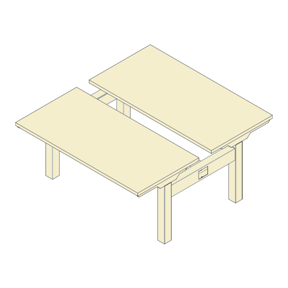
- Page 16 FACING OVERVIEW BOOST Pro Workstation Quantities are for a single facing workstation. Parts may vary depending on project, but install Scan to steps will remain the same. Watch Section...
- Page 17 PARTS LIST BOX CODE DESCRIPTION Adjustable Leg Surface Attachment Bracket BPROF Surface Support Bracket Adjustable Surface Bracket (with Control Box) BPROCB Cross Beam with Cover BPROBRG Power Beam Bridge Data Beam Bridge Power Beam (Assembled) Data Beam Set BPROTPB Power-Opening Rubber Gasket Power &...
- Page 18 1 | SECURE CROSS BEAM TO PAIR OF LEGS Remove cross beam cover. Then, line up pre-drilled holes on inside of beam Scan to with both mounting plate that are located on legs. Connect cross beam to Watch Step each leg using 4 screws. Repeat step for other set of legs. Note: Small center cutout on cross beam should be facing inward.
- Page 19 3 | ATTACH CROSS BEAM COVERS Align beam covers and snap into place. Secure using 3 screws. Scan to Watch Step 4 | PLACE ADJUSTABLE SURFACE BRACKETS ON FRAME Scan to Watch Step Loosen bracket screws and expand surface brackets to align with end of leg caps.
- Page 20 5 | SECURE ADJUSTABLE SURFACE BRACKETS AND ARM BRACKETS TO FRAME Scan to Watch Step Align pre-drilled holes of surface and arm bracket to frame and secure with 4 screws each. 6 | SET WORKSTATION LENGTH Measure from outer edges of legs to determine proper workstation Scan to length.
- Page 21 7 | SECURE POWER BEAM WIDTH Once length of workstation is determined, insert and secure set Scan to screws to underside of beam and tighten to secure. Watch Step Note: Use 2 set screws with 48" workstations and 4 set screws for all other widths.
- Page 22 9 | SECURE DATA TRAY Position outer tray under power beam and secure. Slide inner beam Scan to into outer beam and adjust width to align with pre-drilled holes. Watch Step Secure with screws. 10 | RUN HANDSET CORD THROUGH FRAME NOTCH Scan to Watch Step...
- Page 23 11 | SET SURFACES ON FRAME AND ALIGN Place surfaces on frame and measure for depth of surfaces. Scan to Watch Step 2" 24" Deep Surface 4" 30" Deep Surface...
- Page 24 12 | ATTACH SURFACE Using wood screws provided, secure surfaces to frame. Scan to Watch Step 13 | CONNECT LEG CABLES AND HANDSET CABLE TO CONTROL BOX Scan to Watch Step Note: If adding a height-adjustable return surface, DO NOT connect cables to control box during this step.
- Page 25 14 | SECURE HANDSET Align front of handset with surface edge and secure with wood screws. Scan to Watch Step 15 | POWER UP AND INITIALIZE HANDSET Connect power cord. Press and hold simultaneously for 5 seconds Scan to until both leg columns are in lowest position (Desk will slightly rise, lower Watch Step again, and then beep).
- Page 26 16 | ALIGN AND CONNECT WORKSTATIONS Slide data beam bridge inside data beam. Align second Scan to workstation and push workstations closer together. Connect jumper. Watch Step Remove magnetic strips from power beam bridge and set bridge over jumper. Attach magnetic strips back to bridge. Push workstations together.
- Page 27 17 | INSTALL RUBBER GASKETS AND PLASTIC COVERS Scan to Watch Step OPTIONAL | INSTALL SUPPORT BAR FOR 72" SURFACES Scan to Watch Step...
-
Page 28: Return Surface
RETURN SURFACE OVERVIEW BOOST Pro Workstation Quantities are for a single facing workstation. Parts may vary depending on project, but install Scan to steps will remain the same. Watch Section... - Page 29 PARTS LIST BOX CODE DESCRIPTION Adjustable Return Leg T-Foot Return Leg Support Bracket BPROLF Control Box (for L-Shape) Extension Cable Cable Flat Bracket GBXXXX Return Surface BFB1 Flat Bracket...
- Page 30 1 | CONNECT RETURN LEG TO SUPPORT BRACKET Secure return leg support bracket to return leg from using 6 screws. Scan to Watch Step 2 | REMOVE GLIDE AND INNER BRACKET Twist off leg glide. Using an Allen wrench remove screws that are holding Scan to the inner bracket and remove bracket from leg.
- Page 31 3 | CONNECT T-FOOT TO RETURN LEG Secure T-foot to return leg using 4 bolts. Scan to Watch Step 4 | ATTACH RETURN LEG TO RETURN SURFACE Requires 6 wood screws. Scan to Watch Step Note: The return leg will be centered along the depth of the return surface.
- Page 32 5 | ATTACH FLAT BRACKETS TO MAIN SURFACE Attach 2 small flat brackets and 1 large flat bracket under the main surface Scan to edge using 6 wood screws. Center-align brackets on the edge of main surface Watch Step so that only half of the brackets are being secured to main surface. Note: Leave space between large bracket and inner small bracket to install support bar.
- Page 33 7 | INSTALL SUPPORT BARS Install support bar under main surface and return with wood screws. Scan to Watch Step 8 | INSTALL RETURN CONTROL BOX Remove existing control box from main surface and replace with return Scan to control box. Secure with existing screws. Connect all three leg cables, Watch Step handset, and power cable.
- Page 34 9 | POWER UP AND INITIALIZE HANDSET Connect power cord. Press and hold simultaneously for Scan to 5 seconds until both leg columns are in lowest position (Desk will Watch Step slightly rise, lower again, and then beep). Release buttons. The system is now operational.
- Page 36 PANEL BRACKETS OVERVIEW BOOST Pro Workstation Quantities are for a single facing workstations. Parts may vary depending on project, but install Scan to steps will remain the same. Watch Section...
-
Page 37: Adjustable Panel Brackets
PARTS LIST BOX CODE DESCRIPTION BPROAEPB Adjustable Panel Bracket (Set of 2) - Page 38 OPTIONAL | ADJUST BRACKET TO FIT WIDTH OF LAMINATE PANEL Scan to Watch Step If working with adjustable panel bracket, you have the flexibility to adjust bracket to accommodate the width of a custom panel by detaching bracket and rotating, if needed.
- Page 39 1 | ATTACH PANEL BRACKET TO WORKSTATION LEG With a partner, lift workstation up and slide bracket under Scan to workstation leg. Sit workstation back down into the panel bracket. Watch Step Slide bracket up workstation leg. If working with adjustable bracket, adjust depth accordingly by loosening screws.
-
Page 40: Beam-Mounted Divider Clippers
BEAM-MOUNTED DIVIDER CLIPPERS OVERVIEW BOOST Pro Workstation Quantities are for a single facing workstation. Parts may vary depending on project, but install Scan to steps will remain the same. Watch Section... - Page 41 PARTS LIST BOX CODE DESCRIPTION Beam-Mounted Divider Clipper (Set of 2) BPROBRK Machine Screw Divider Clipper Base BPROMBRG Rubber Shim (For Glass Divider)
- Page 42 1 | ATTACH CLIPPER BASE TO FRAME Secure clipper base to frame using 4 screws for each base. Scan to Watch Step OPTIONAL | INSTALL RUBBER SHIM If installing a glass divider, set rubber shim inside beam-mounted Scan to divider clippers by guiding shim down clipper with a screwdriver. Watch Step Bring screwdriver back up to open up rubber shim.
- Page 43 2 | ATTACH CLIPPER TO CLIPPER BASE Sit clipper on clipper base and align holes. Secure using 4 screws. Scan to Watch Step 3 | INSTALL DIVIDER Scan to Watch Step...
-
Page 44: Steel End Panel
STEEL END PANEL OVERVIEW BOOST Pro Workstation Quantities are for a single facing workstation. Parts may vary depending on project, but install Scan to steps will remain the same. Watch Section... - Page 45 PARTS LIST BOXCODE DESCRIPTION Steel End Panel BPROEP Machine Screw...
- Page 46 1 | SNAP STEEL END PANEL ON CROSS BEAM Scan to Watch Step...
- Page 47 2 | SECURE STEEL END PANEL Secure using 3 screws. Scan to Watch Step...
- Page 48 1-866-304-7197 | inspire@mycleardesign.com | mycleardesign.com © 2023 Clear Design | Version 23.0.5...
Need help?
Do you have a question about the BOOST PRO BP-1 and is the answer not in the manual?
Questions and answers