
Related Manuals for CLEAR DESIGN BOOST 120-DEGREE


Summary of Contents for CLEAR DESIGN BOOST 120-DEGREE
- Page 1 BHALGSA BOOST 120-DEGREE HEIGHT-ADJUSTABLE WORKSTATION A1 | A2 Includes Add-Ons: General Installation Guide...
- Page 3 EDITION CODE BHALGSA :: Workstation ............1 ADD-ONS :: Slim Pedestal ..............11 :: Cable Tray ..............15...
-
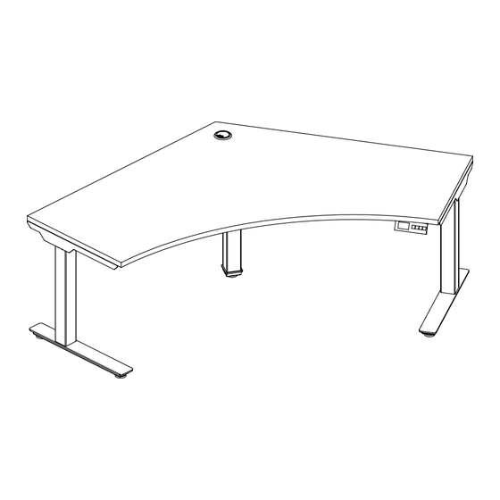
Page 4: Workstation Overview
WORKSTATION OVERVIEW BOOST 120-Degree Height-Adjustable All parts listed are for a single workstation; additional parts will be needed for additional workstations. -
Page 5: Parts List
PARTS LIST CODE DESCRIPTION GB120V2 Surface Right & Left-Adjustable Beam Feet (Set of 2) 23" Arm Bracket Center Post Brackets (L, REAR, & R) Center Post Base Leg with Motor Handset BHALGSA Glides Extension Cords (SHRT, MED, & LG) Power Cable Screw (A) Screw (B) Screw (C) - Page 6 1 | ASSEMBLE LEG POSTS SEPARATELY Attach center leg with motor to the center post brackets using screws (A). Then, attach side legs with motor and arm brackets to left and right adjustable beams. Note: Replace the default arm brackets if workstation requires BHA19 or T-brackets.
- Page 7 2 | SECURE LEG POSTS ON SURFACE Secure leg posts to the surface using screws (F). Note: If using surface-mounted dividers, keep the frame 1.5 inches inset from the surface edge. If not using surface-mounted dividers, bring frame flushed to edge of surface.
- Page 8 4 | INSTALL FEET, GLIDERS, AND CONTROL BOX , THEN SECURE POWER. Install feet using screws (D) for outside legs. Install center post base to center leg using screws (E). Mount control box to the post beam using screw (G). Then, secure power cord to the control box. Mount handset using wood screws (C) and attach to control box.
- Page 10 A3: SLIM PEDESTAL OVERVIEW BOOST 120-Degree Height-Adjustable All parts listed are for a single slim pedestal; additional parts will be needed for additional slim pedestals.
- Page 11 PARTS LIST CODE DESCRIPTION Large Mounting Bracket BFSLM.SM Small Mounting Bracket BFSLM Slim Pedestal Machine Screw BFSLM.HW Wood Screw...
- Page 12 1 | SECURE BRACKETS TO SLIM PEDESTAL Align large mounting bracket to front of pedestal and align small mounting bracket to back. Secure both brackets using provided screws.
- Page 13 2 | ATTACH SLIM PEDESTAL TO SURFACE Secure pedestal to surface using wood screws. The pedestal brackets will connect on either side of the center beam.
- Page 14 A4: CABLE TRAY OVERVIEW BOOST 120-Degree Height-Adjustable All parts listed are for a single cable tray; additional parts will be needed for additional cable trays.
- Page 15 PARTS LIST CODE DESCRIPTION Surface-Mount Cable Management Tray BHCT Wood Screws...
- Page 16 1 | EXTEND CABLE TRAY TO DESIRED LENGTH Extension range: 25"–45".
- Page 17 2 | ATTACH CABLE TRAY TO SURFACE Attach cable tray using wood screws.
- Page 18 1-866-304-7197 | inspire@mycleardesign.com | mycleardesign.com © 2022 Clear Design | Version 22.1.3...
Need help?
Do you have a question about the BOOST 120-DEGREE and is the answer not in the manual?
Questions and answers