
Related Manuals for CLEAR DESIGN BL-3


Summary of Contents for CLEAR DESIGN BL-3
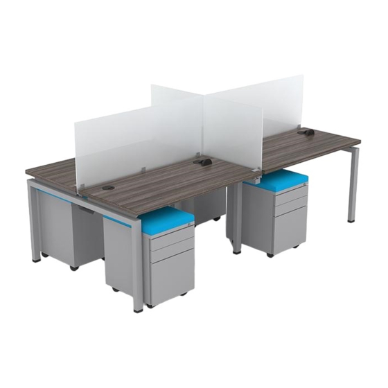
- Page 1 BL–3 BLADE FACING WORKSTATION Includes Add-ons A1 | A2 | A5 | A6 | A7 *General Guide | See Master Plan...
- Page 2 EDITION CODE BL–1 – BLADE Facing Workstation ............1 Optional Surface Support ...............11 BLADE Conference .................. 12 Add-Ons – BLADE Cable Tray (Leg Mounted) ..........4 – Surface Mounted Dividers ............8 – Lamintate Surface-Height End Panels ........15 – Lamintate Divider-Height End Panels ........17 –...
- Page 3 PARTS LIST PRODUCT CODE BL60 BL48INT BLPB2/BLBB3 Main Surface BASB72 (*will be added if surface is 72" of larger) * Process will repeat for longer pods of workstations and is the same for conference tables...
- Page 4 1 | ASSEMBLE INTERMEDIATE LEG Align bracket with leg holes and bolt in place. Connect 4 brackets to the leg. Insert 2 bolts per bracket to secure in place. 48" 60"...
- Page 5 2 | JOIN END AND INTERMEDIATE LEG Insert the beam tabs into the leg brackets. Guide the beam tabs into the bracket holes, there should be no gap between the beam and legs. Using a rubber mallet, hammer the beam to lock in place. 3 | JOIN SECOND END LEG TO INTERMEDIATE LEG Insert the beam tabs into the leg brackets.
- Page 6 4 | BOLT DOWN BEAM-TO LEG LOCK PLATES Note: The beam lock plates will not fit if there is a gap between the beam and the leg. 5 | MEASURE BEAM WIDTH AND LOCK Measure from end leg to end leg until you find the approximate width of the worksurfaces.
- Page 7 CABLE TRAY BL–3 | A1 PARTS LIST PRODUCT CODE BCTLM (set of 2) BTEC or BNTEC (set of 2) *if applicable BL-8 IF WORKSTATIONS HAVE POWER, REFER TO BLADE POWER GUIDE...
- Page 8 1 | ATTACH CABLE TRAY HANGERS AND END CAPS* Align slots on the cable tray and secure with 2 bolts from the bottom. These hangers will mount to the workstation. Insert Beam Grommet Covers. *NOTE: End Caps (BTEC) are optional, follow the same install process with or without end caps.
- Page 9 3 | LEG MOUNT CABLE TRAY Bolt a hanger to both ends of the cable tray to mount to the workstation. Screw the cable tray hangers to the legs. Insert 2 screws per hanger. Tighten beam lock. BL-8 IF WORKSTATIONS HAVE POWER, REFER TO BLADE POWER GUIDE...
- Page 10 6 | SURFACE INSTALLATION - RULES Measure from the inner surface of the leg bracket to the outer edge of the surface. ” Option 1: If you are installing dividers to monitor arms, leave space between surfaces ” 24" • deep surfaces, measure ”...
- Page 11 7 | SECURE FIRST & SECOND SURFACE Place the surface on top of the frame and position according to the guidelines. Insert wood screws into the leg brackets and secure to the underside of the surface. 9 | PLACE BRACKETS ON FACING EDGE Clamp bracket to the surface's side edge and tighten the vertical bolt against the surface to secure the bracket.
- Page 12 10 | SECURE THIRD SURFACE Place the surface on top of the frame and position according to the guidelines. Insert wood screws into the leg brackets and secure to the underside of the surface. 11 | CLAMP BRACKETS TO SIDE EDGES Clamp bracket to the surface's side edge and tighten the vertical bolt against the surface to secure the bracket.
- Page 13 12 | SECURE FOURTH SURFACE Place the surface on top of the frame and position according to the guidelines. Insert wood screws into the leg brackets and secure to the underside of the surface. 13 | FINAL STEPS Insert final wood screws and tighten beam locks...
- Page 14 OPTIONAL | INSTALL ANTI-SAG BAR If you surface is 72" or larger, use 10 wood screws to install the anti-sag bar to the underside of your surface. Note: Repeat for across all workstations...
- Page 15 CONFERENCE PARTS LIST PRODUCT CODE BL60 BL48INT Main Surface * Process will repeat for longer pods of workstations and is the same for conference tables...
- Page 16 CONFERENCE INSTALLATION Follow steps 1-5 for Facing Workstation Assembly. Replace surface with one or more surfaces to complete a conference table. Align the outer sides of the surfaces flush and parallel with the outer sides of the end legs and secure with wood screws. Align Flush Align Flush...
- Page 17 FINAL STEPS Insert final wood screws and tighten beam locks...
- Page 18 END PANELS BL–3 | A6 PARTS LIST PRODUCT CODE LEPBL1 GBEP## or WABEPIS.(A-D) * Quantities are for one panel...
- Page 19 1 | SECURE BRACKET FOR OUTER PANELS TO END LEGS Attach four brackets to each BLADE end leg using the self-tapping screws. The front of the bracket will align flush with outside edge of the leg. Align Flush 2 | ATTACH END PANEL Slide end panels into place and adjust until flush with bracket.
- Page 20 END PANELS BL–3 | A6 PARTS LIST PRODUCT CODE LEPBL1 GBEPSS## or WABEPDH.(A-D) * Quantities are for one panel...
- Page 21 1 | SECURE BRACKET FOR OUTER PANELS TO END LEGS Attach 4 brackets to each BLADE end leg using the self-tapping screws. The front of the bracket will align flush with outside edge of the leg. Align Flush 2 | ATTACH END PANEL Slide end panels into place and adjust until flush with bracket.
- Page 22 END PANELS BL–3 | A7 PARTS LIST PRODUCT CODE BEP## or BCEP## * Quantity is for one panel...
- Page 23 1 | SECURE PANELS TO END LEGS Slide the end panel into place and adjust until either flush with outside of leg or slightly recessed. Align Flush Slightly Recessed 2 | ATTACH END PANEL Use 4-6 self-tapping screws to secure panel to each leg.
- Page 24 210.648.2095 | mycleardesign.com © 2021 Clear Design. All rights reserved.
Need help?
Do you have a question about the BL-3 and is the answer not in the manual?
Questions and answers