Advertisement
Quick Links
Advertisement

Related Manuals for CLEAR DESIGN EDGE ESHA


Summary of Contents for CLEAR DESIGN EDGE ESHA
- Page 1 ESHA EDGE HEIGHT-ADJUSTABLE DESK Includes Add-Ons: A1 | A2 General Installation Guide...
- Page 3 EDITION CODE ESHA :: Stand-Alone Desk ............1 ADD-ONS :: Modesty Panel ............... 11 :: Return Surface ............. 15...
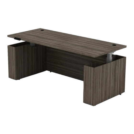
- Page 4 STAND-ALONE DESK OVERVIEW EDGE Height-Adjustable Desk Quantities are for a single Stand-Alone Desk. Parts may vary depending on project, but install steps will remain the same.
- Page 5 PARTS LIST CODE DESCRIPTION Adjustable Leg Surface Attachment Bracket Surface Support Bracket BPROF Width Adjusting Bracket Control Box* Cable* BPRO24F 24" C-Leg Foot GB3072 Main Surface BASB72 42" Support Bar ESHALC.L Left-Leg Cover ESHALC.R Right-Leg Cover ESHAFP72 Floor Modesty Panel T-Bracket LEPBL1-K Wood Screw...
- Page 6 1 | CONNECT LEGS AND SUPPORT BRACKETS TO ADJUSTABLE SURFACE BRACKET Slide one support bracket underneath each end of adjustable surface bracket. Set one leg at each end. Be sure all pre-drilled holes are aligned and secure with machine screws. Note: Longer side of support brackets will be facing front of workstation and welded brackets from legs will be facing back of workstation.
- Page 7 2 | SET FRAME ON SURFACE AND SET LENGTH Align frame with surface width and measure from outer edges of workstation legs to determine proper workstation length. Frame length will measure to 68". Inset will be 2" for each side. Note: Run handset cable through cutout at bottom of frame.
- Page 8 3 | TIGHTEN SCREWS ON ADJUSTABLE SURFACE BRACKET Tighten adjustable surface brackets screws to secure length. 4 | SECURE FRAME & HANDSET TO SURFACE Using wood screws, attach frame to surface and tighten screws on adjustable center bracket.
- Page 9 5 | REMOVE GLIDE AND INNER BRACKET Twist off both glides. Then, using an Allen wrench remove screws that are holding the inner brackets. Note: Glide and inner brackets must be removed so feet can be added to workstation. 6 | SECURE FEET TO LEGS Using 4 screws for each foot, secure to legs with longer side of foot facing the front of workstation.
- Page 10 7 | CONNECT LEG CABLES AND HANDSET CABLE TO CONTROL BOX Note: If adding a height-adjustable return surface, DO NOT connect cables or handset to control box. A return surface control box will be installed on PAGE 24, replacing existing control box. 8 | SECURE SUPPORT BAR Secure support bar to center of the main surface.
- Page 11 9 | REMOVE PANEL FROM LEG COVERS Slide out panels from both leg covers and set aside. Right Side Left Side 10 | SLIDE LEG COVERS AROUND FRAME LEGS Leg covers should align with sides of surface, and front/back edge of surface. Left Side Right Side...
- Page 12 11 | INSTALL LEG COVER PANELS Install panels back into leg covers.
- Page 13 12 | ATTACH T-BRACKETS TO FLOOR MODESTY PANEL Secure 4 T-brackets using provided wood screws. 18" 6"...
- Page 14 13 | ATTACH FLOOR MODESTY PANEL TO LEG COVERS Secure modesty panel with T-brackets using provided wood screws. The floor modesty panel will be inset 3/4" from the leg covers. 3/4" Side view 14 | POWER UP AND INITIALIZE Note: If installing a height-adjustable return surface, skip step. Power up and initialize will occur on PAGE 24.
- Page 15 OPTIONAL | MONITOR ARM Follow proper instructions when installing monitor arm. Only install monitor arms that fit inside grommets. Do not mount to edge of desk.
- Page 16 LAMINATE MODESTY PANEL OVERVIEW EDGE Shell Quantities are for a single EDGE Shell Laminate Modesty Panel . Parts may vary depending on project, but install steps will remain the same.
- Page 17 PARTS LIST CODE DESCRIPTION Laminate Modesty Panel GLMP Machine Screws L-Brackets BMPBFB Wood Screws...
- Page 18 1 | SECURE BRACKETS TO MODESTY PANEL Connect the L-bracket to the modesty panel using screws. Secure tightly.
- Page 19 2 | ATTACH MODESTY PANEL TO SURFACE Attach modesty panel to surface using wood screws provided with brackets. Panel will be center aligned and inset 2.5" from back of surface to edge of bracket. 16.5" 16.5" 2.5" Side View...
- Page 20 RETURN SURFACE OVERVIEW EDGE Shell Quantities are for a single EDGE Shell Return Surface. Parts may vary depending on project, but install steps will remain the same.
- Page 21 PARTS LIST CODE DESCRIPTION Adjustable Return Leg T-Foot Surface Attachment Bracket Return Leg Support Bracket BPROLF Control Box L-Shape Extended Cable Cable Large Flat Bracket GBXXXX Return Surface BFB1 Small Flat Bracket ESHALC Return-Leg Cover...
- Page 22 1 | CONNECT RETURN LEG TO SUPPORT BRACKET Secure return leg support bracket to return leg from using 6 screws. 2 | REMOVE GLIDE AND INNER BRACKET Twist off leg glide. Then, using an Allen wrench remove screws that are holding the inner bracket and remove bracket from leg.
- Page 23 3 | CONNECT T-FOOT TO RETURN LEG Secure T-foot to return leg using 4 screws. 4 | ATTACH RETURN LEG TO RETURN SURFACE Requires 4 wood screws. Note: The return leg will be centered along the depth of the return surface. 2.25"...
- Page 24 4 | ATTACH FLAT BRACKETS TO MAIN SURFACE Attach 2 flat brackets under the main surface using 4 wood screws. See measurements below. 17.25" 2" Bottom View 5 | ATTACH RETURN SURFACE TO MAIN SURFACE Position return surface on top of attached brackets and secure with 4 wood screws.
- Page 25 6 | ATTACH SUPPORT BAR Center and secure support bar between flat brackets for extra support and rigidity. 7 | REMOVE BACK PANEL FROM RETURN-LEG COVER Slide out back panel from return-leg cover and set aside.
- Page 26 8 | SLIDE RETURN-LEG COVER AROUND RETURN LEG Return-leg cover should align with sides of return surface, and front/back edge of return surface. 9 | INSTALL RETURN-LEG COVER BACK PANEL Install back panel back into the return-leg cover.
- Page 27 8 | INSTALL RETURN CONTROL BOX Remove existing control box from main surface and replace with return control box. Secure with existing screws. Connect all three leg cables, handset, and power cable. 11 | POWER UP AND INITIALIZE Connect cord to power source then press and hold and simultaneously for 5 seconds until both leg columns are in lowest position.
- Page 28 1-866-304-7197 | inspire@mycleardesign.com | mycleardesign.com © 2023 Clear Design | Version 23.0.9...
Need help?
Do you have a question about the EDGE ESHA and is the answer not in the manual?
Questions and answers