
Subscribe to Our Youtube Channel
Related Manuals for ADLINK Technology NuPRO-720


Summary of Contents for ADLINK Technology NuPRO-720
- Page 1 NuPRO-720 PICMG 1.0 Full-Size AMD Geode™ LX 800 SBC User’s Manual Manual Revision: 2.10 Revision Date: October 29, 2008 Part No: 50-13059-1010 Advance Technologies; Automate the World.
-
Page 2: Revision History
Revision History Revision Release Date Description of Change(s) 2.00 2008/04/03 Initial Release 2.01 2008/05/19 Correct address Remove Windows 2000 support; correct 2.10 2008/10/29 operating system and driver installation... -
Page 3: Preface
NuPRO-720 Preface Copyright 2008 ADLINK Technology Inc. This document contains proprietary information protected by copy- right. All rights are reserved. No part of this manual may be repro- duced by any mechanical, electronic, or other means in any form without prior written permission of the manufacturer. - Page 4 Using this Manual Audience and Scope The NuPRO-720 User’s Manual is intended for hardware technicians and systems operators with knowledge of installing, configuring and operating industrial grade single board computers. Manual Organization This manual is organized as follows: Preface: Presents important copyright notifications, disclaimers, trademarks, and associated information on the proper understand- ing and usage of this document and its associated product(s).
- Page 5 NuPRO-720 Conventions Take note of the following conventions used throughout this manual to make sure that users perform certain tasks and instructions properly. Additional information, aids, and tips that help users perform tasks. NOTE: NOTE: Information to prevent minor physical injury, component dam- age, data loss, and/or program corruption when trying to com- plete a task.
- Page 6 This page intentionally left blank. Preface...
-
Page 7: Table Of Contents
NuPRO-720 Table of Contents NuPRO-720 ................i Revision History..............ii Preface ..................iii Table of Contents..............vii List of Figures ................ ix List of Tables................xi 1 Introduction ................ 1 Package Contents ............... 1 Overview................2 Features................2 Applications ................. 3 Specifications............... - Page 8 CN15 & CN16 - USB Connectors ......... 24 IDE - UltraATA-133 IDE Connector ......25 JP1 - System Panel Connector ........26 SATA1 & SATA2 - Serial-ATA Ports ......26 3 Getting Started ..............27 Memory Module Installation ..........27 CompactFlash Card Installation.........
-
Page 9: List Of Figures
NuPRO-720 List of Figures Figure 1-1: NuPRO-720 Functional Diagram ........7 Figure 1-2: NuPRO-720 Board Layout..........14 Figure 1-3: Board Dimensions ............15 Figure 2-1: Board Connectors & Jumpers Layout......18 Figure 2-2: CRT/VGA Port & Pin Assignments ........ 19 Figure 2-3: CompactFlash Socket &... - Page 10 This page intentionally left blank. List of Figures...
-
Page 11: List Of Tables
NuPRO-720 List of Tables Table 1-1: General Specifications............. 4 Table 1-2: Power Consumption Specifications ......... 5 Table 1-3: I/O Connectivity Table ............. 6 List of Tables... - Page 12 This page intentionally left blank. List of Tables...
-
Page 13: Introduction
NuPRO-720 Introduction This chapter will introduce the NuPRO-720, its features, specifica- tions and applications. This chapter also provides detailed infor- mation about the mechanics of the product and technical information to assist users. 1.1 Package Contents Please check that your package contains the items below. If you discover damaged or missing items, please contact your vendor. -
Page 14: Overview
1.2 Overview ADLINK’s NuPRO-720 is a full-size system host board in PICMG 1.0 form factor. It is based on the AMD Geode LX 800 pro- cessor and CS5536 companion device (South bridge) allowing ultra low power consumption and fanless capability. In addition to... -
Page 15: Applications
NuPRO-720 1.4 Applications The NuPRO-720 is specifically designed for industrial automation and system integrators looking for fanless SBC solutions in ultra- low power packages and ample I/O connectivity. Several specific usages of NuPRO720 are: Industrial automation Intelligent transportation systems 2D arcade games Electronic billboards IPC distributors &... -
Page 16: Specifications
1.5 Specifications System • AMD Geode LX 800 Processor 500 MHz, 128 KB L2 Cache Chipset • AMD Geode CS5536 Companion Device Memory • Two 184-pin DIMM sockets • Supports DDR-400 SDRAM, up to 2 GB BIOS • Phoenix-Award BIOS with 2 Mb Flash ROM Watch Dog Timer •... - Page 17 NuPRO-720 Power Consumption +12V 5VSB Power Requirements (amps) Light-loading 1.761 0.363 0.01 Average-loading 1.938 0.375 0.011 Full-loading 2.35 0.439 0.033 +12V 5VSB Total Power Requirements (watts) Light-loading 8.805 4.356 0.05 13.211 Average-loading 9.69 0.055 14.245 Full-loading 11.75 5.268 0.165 17.183...
-
Page 18: I/O Connectivity Table
1.6 I/O Connectivity Table Golden Onboard Bracket Finger (pin header) VGA / CRT — — LAN (RJ-45) — — (with LED indication) LAN (RJ-45) — — (with LED indication) PS/2 KB/MS — — USB1 — — USB2 — — COM1 —... -
Page 19: Functional Diagram
Ethernet Intel 82551ER CS5536 RAID Controller AC97 USB 2.0 VIA VT6421 Controller Controller Internal 4 ports 2x SATA 150 BIOS Header for KB/Mouse DB-AC97S Super I/O Winbond Hardware W83627 RS-232 Monitor RS-232/ 422/485/ 485+ Figure 1-1: NuPRO-720 Functional Diagram Introduction... -
Page 20: Functional Description
0.15 micron process Packaged in 396-terminal BGU Memory NuPRO-720 supports 184-pin DDR sockets, up to 2 GB. The GeodeLink Memory Controller (GLMC) module supports the Uni- fied Memory Architecture (UMA) of the Geode GX processor and controls a 64-bit DDR SDRAM interface without any external buff- ering. - Page 21 Supports low power mode Highly configurable to obtain best performance for installed DRAM Display NuPRO-720 supports VGA output. The VGA function is integrated in the Geode LX Processor. Supports up to 16.8 million colors (24-bit) Supports resolutions up to 1600 x 1200...
- Page 22 PCI Arbitration NuPRO-720 supports seven on-board PCI devices. The PCI local bus supports the Geode LX, CS5536, PCI2050BPDV and IT8888G devices. The PCI external bus supports VT6421A and the two 82551ER devices. Because the LX processor supports only three pairs, namely PCI REQ# and GNT# arbiters; NuPRO- 720 offers an additional Arbiter (AT123S).
- Page 23 Low power 3.3 V device ISA Bridge NuPRO-720 uses a IT8888G PCI-to-ISA bridge single function device to support its ISA bus. The IT8888G's 32-bit PCI bus inter- face is compliant with PCI Specification V2.1 and supports both PCI Bus Master & Slave.
- Page 24 Geode CS5536 companion device also supports two optional pins: LDRQ# and SERIRQ. The LPC interface supports memory, I/O, DMA, and Intel's Firmware Hub Interface. In NuPRO-720, There are three devices (Super I/O, BIOS and LPC Debug Port) routed with the LPC bus. The following are features of LPC bus for NuPRO-720: Based on Intel's Low Pin Count (LPC) Specification v1.0...
- Page 25 The S-ATA drive transfer rate is capable of up to 150 MB/s per channel Single channel master mode hard disk controller supporting two enhanced IDE devices Supports ATA PIO mode 4, multi-word DMA-mode 2 drivers and UltraDMA-mode 6 BIOS NuPRO-720 supports Phoenix -Award BIOS with 2 Mb Flash Introduction...
-
Page 26: Board Layout
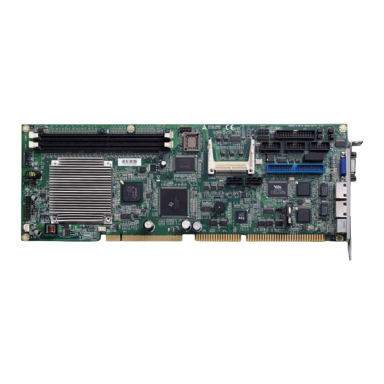
1.9 Board Layout Figure 1-2: NuPRO-720 Board Layout Introduction... -
Page 27: Mechanical Drawings
NuPRO-720 1.10 Mechanical Drawings Dimensions in mm 30.6 119.92 Figure 1-3: Board Dimensions Introduction... - Page 28 This page intentionally left blank. Introduction...
-
Page 29: Connectors & Jumpers
NuPRO-720 Connectors & Jumpers The connectors and jumpers on the NuPRO-720 allow you to con- nect and configure external devices such as keyboard, floppy disk drives, hard disk drives, printers, etc. The following subsections specify the pin assignments for connectors and jumper blocks on the NuPRO-720. -
Page 30: Motherboard Layout
2.1 Motherboard Layout CN11 CN10 CN12 CN13 CN14 CN16 SATA 2 CN15 SATA 1 Figure 2-1: Board Connectors & Jumpers Layout Connectors & Jumpers... -
Page 31: Pin Definitions
NuPRO-720 2.2 Pin Definitions CN1 - CRT/VGA Port Figure 2-2: CRT/VGA Port & Pin Assignments SIGNAL FUNCTION Analog RED GREEN Analog GREEN BLUE Analog BLUE No Connect Ground Ground Ground Ground Ground Ground No connect DDCDAT DDC Data for CRT... -
Page 32: Cn2 - Compactflash Socket
CN2 - CompactFlash Socket Figure 2-3: CompactFlash Socket & Pin Assignments Signal Name Signal Name CF_D3 CF_D11 CF_D4 CF_D12 CF_D5 CF_D13 CF_D6 CF_D14 CF_D7 CF_D15 CF_CS0 CF_CS1 CF_DIOR-L CF_DIOW-L P3V3 CNCF_IORDY P3V3 P3V3 PCSEL CF_RESET CF_A2 CF_A1 P3V3 CF_A0 CF_D0 CF_D1 CF_D8 CF_D2... -
Page 33: Cn4 - Ac'97 Audio Connector
NuPRO-720 CN4 - AC’97 Audio Connector Figure 2-5: Audio Connector & Pin Assignments PIN # SIGNAL NAME PIN # SIGNAL NAME SOUT 3.3V SYNC RESET CN5 - LPT Connector Figure 2-6: LPT Connector & Pin Assignments PIN # SIGNAL NAME... -
Page 34: Cn7 & Cn8 - Fan Connectors
CN7 & CN8 - Fan Connectors Figure 2-7: Fan Connectors & Pin Assignments PIN # SIGNAL NAME SENSE CN10 & CN11 - LAN1 & LAN2 Ports Figure 2-8: LAN Ports (RJ-45) & Pin Assignments Signal Transmit Data + Transmit Data - Receive Data + Termination Termination... -
Page 35: Cn13 - Com2 Connector (Rs-232 Only)
NuPRO-720 CN13 - COM2 Connector (RS-232 Only) Figure 2-10: COM2 Connector & Pin Assignments SIGNAL FUNCTION Data Carrier Detect Receive Data Transmit Data Data Terminal Ready Ground Data Set Ready Request to Send Clear to Send Ring Indicate No Connect CN14 - COM 1 Connector (RS-232/422/485/485+) Figure 2-11: COM1 Connector &... -
Page 36: Com1 Multiple Function Jumper (Jp3/4/5/6)
COM1 Multiple Function Jumper (JP3/4/5/6) Figure 2-12: JP3, JP4, JP5, & JP6 with Jumper Table RS-232 RS-422 RS-485 RS-485+ 1-3, 2-4 3-5, 4-6 3-5, 4-6 3-5, 4-6 1-3, 2-4 1-3, 2-4 3-5, 4-6 1-3, 2-4 3-5, 4-6 3-5, 4-6 3-5, 4-6 CN15 &... -
Page 37: Ide - Ultraata-133 Ide Connector
NuPRO-720 IDE - UltraATA-133 IDE Connector Figure 2-14: IDE Connector and Pin Assignments SIGNAL PIN # PIN # SIGNAL IDERST# Ground PDD 7 PDD 8 PDD 6 PDD 9 PDD 5 PDD 10 PDD 4 PDD 11 PDD 3 PDD 12... -
Page 38: Jp1 - System Panel Connector
JP1 - System Panel Connector Figure 2-15: JP1 and Pin Assignments PIN # SIGNAL NAME PIN # SIGNAL NAME Buzzer POWER LED RESET HDD LED PS ON 5VSB POWER BTW SATA1 & SATA2 - Serial-ATA Ports Figure 2-16: SATA Connectors and Pin Assignments SIGNAL FUNCTION Ground... -
Page 39: Getting Started
184-pin footprint. The DDR modules are notched to facilitate correct installation on the DIMM sockets. Memory Configuration Options The NuPRO-720 allows you to install 256 MB, 512 MB and 1GB unbuffered non-ECC DDR DIMMs into the DIMM sockets following these configuration options: It is recommended that you install DIMMs with the same CAS latency. - Page 40 3. Align the memory module on the socket making sure that the notch matches the break on the socket. Notch Break 4. Insert the module firmly into the slot until the retaining clips snap back inwards and the module is securely seated.
-
Page 41: Compactflash Card Installation
NuPRO-720 3.2 CompactFlash Card Installation The NuPRO-720 supports standard CompactFlash memory cards via the CN2 CompactFlash type II socket. To install a CompactFlash card: 1. Locate the CN2 connector - CompactFlash type II socket slot on the NuPRO-720. 2. Take note of the pin holes on the card and the guide rails of the socket to ensure proper orientation when installing. - Page 42 3. Align the card on the socket making sure that the guide rails line up smoothly. Applying too much force may damage the card and/or the socket. 4. Insert the card firmly into the socket until the card and be sure that the socket pins are completely inserted into the card pin holes.
-
Page 43: Operating System Installation
NuPRO-720 3.3 Operating System Installation The NuPRO-720 supports Microsoft Windows XP. In order for the system to recognize the IDE and SATA devices supported by the VIA VT6421L Controller, the SATA controller driver must be installed immediately after booting from the Windows Setup CD. -
Page 44: Driver Installation
3.4 Driver Installation This section provides information on how to install the NuPRO-720 device drivers under Windows XP. The device drivers are located in the following ADLINK All-in-One CD directories: Chipset driver \NuPRO\NuPRO-720\Chipset\ Display driver \NuPRO\NuPRO-720\VGA\ LAN driver \NuPRO\NuPRO-720\Ethernet\ ISA driver... - Page 45 NuPRO-720 The following instructions will explain specific driver installation procedures. Getting Started...
-
Page 46: Chipset Driver
Chipset Driver This section describes how to manually install the chipset driver. 1. Follow the basic instructions laid out in the General Installation Guidelines section above. 2. In the ‘Computer Management’ window on the right side right click the ‘Entertainment Encryption/Decryp- tion Controller’. - Page 47 NuPRO-720 4. The ‘Hardware Update Wizard’ dialog box will open. Read the instructions and then click option 3, ‘No, not this time’, then click ‘Next’ to continue. Getting Started...
- Page 48 6. At the next screen select ‘Search for the best driver in these locations’ and click the tab ‘Include this location in the search’. Click the ‘Browse’ button and locate the following folder/file in the ADLINK All-in-One CD: X:\NuPRO\NuPRO-720\Chipset\ Press ‘Next’ to install the inf files. Getting Started...
- Page 49 NuPRO-720 7. After successfully installing the files, the ‘Hardware Update Wizard’ will display the following screen. Click ‘Finish’. Getting Started...
-
Page 50: Display Driver
‘Include this location in the search’. Click the ‘Browse’ button and locate the following folder/file in the ADLINK All-in-One CD: X:\NuPRO\NuPRO-720\Chipset\ Press ‘Next’ to install the inf files. 7. You may receive a ‘Hardware Installation’ notice that... - Page 51 NuPRO-720 8. After successfully installing the files, the ‘Hardware Update Wizard’ will display the ‘Completing the Hard- ware Update Wizard’ screen. Click ‘Finish’. 9. You may now setup the display properties from the Win- dows Control Panel normally. Getting Started...
-
Page 52: Lan Driver
‘Include this location in the search’. Click the ‘Browse’ button and locate the following folder/file in the ADLINK All-in-One CD: X:\NuPRO\NuPRO-720\Ethernet Press ‘Next’ to install the inf files. 7. You may receive a ‘Hardware Installation’ notice that... - Page 53 NuPRO-720 8. After successfully installing the files, the ‘Hardware Update Wizard’ will display the ‘Completing the Hard- ware Update Wizard’ screen. Click ‘Finish’. 9. When you install the second Ethernet controller driver you may receive a ‘Hardware Update Wizard’ notice informing you that the LAN driver is not digitally signed.
- Page 54 10.The e100exp.inf file should be located at: X:\NuPRO\NuPRO-720\Ethernet\ 11. After the location and installation of the files, you may setup the network properties from the Windows Control Panel normally. Getting Started...
-
Page 55: Isa Driver
NuPRO-720 ISA Driver Follow these instructions to install the ISA driver. 1. Follow the basic instructions laid out in the General Installation Guidelines section. 2. In the ‘Computer Management’ window on the right side right click the ‘Other PCI Bridge Devices’. -
Page 56: Audio Driver
‘Include this location in the search’. Click the ‘Browse’ button and locate the following folder/file in the ADLINK All-in-One CD: X:\NuPRO\NuPRO-720\Audio Press ‘Next’ to install the inf files. 7. You may receive a ‘Hardware Installation’ notice that... - Page 57 NuPRO-720 DB-AC97S Audio Daughter Board Follow these instructions to install the driver for the optional DB-AC97S daughter board. 1. Place the ADLINK All-in-One CD to the optical drive. 2. Locate the following directory: X:\Audio Daughter Board\DB-AC97S\98me2k_driver\wdm_drv2\ then double-click on the setup.exe file to start installation.
- Page 58 This page intentionally left blank. Getting Started...
-
Page 59: Watch Dog Timer
NuPRO-720 Watch Dog Timer NuPRO-720 implements a watch dog timer (WDT) embedded in the LPC based Winbond 83627HG Super I/O controller. The Watchdog timer consists of a one-second/minute resolution counter (CRF6 on logical device 8 of 83627HG) and two watch dog control registers (CRF5 and CRF7 on logical device 8). - Page 60 The example shown below resets the system after 15 seconds. Both keyboard and mouse interrupts will reload the WDT from CRF6. begin: ;——————————————————————————————————————————————— ; Enter extended function mode, interrupt double-write ;——————————————————————————————————————————————— mov dx,2Eh mov al,87h out dx,al out dx,al mov dx,2Eh mov al,2bh ;CR2B, bit4 ->...
- Page 61 NuPRO-720 out dx,al mov dx,2Fh mov al,00h ;bit3 -> 0 = second ;bit3 -> 1 = minute out dx,al mov dx,2Eh mov al,0F6h ;device 8, CRF6 out dx,al mov dx,2Fh mov al,0Fh out dx,al ;——————————————————————————————————————————————— ; Exit extended function mode ;———————————————————————————————————————————————...
- Page 62 This page intentionally left blank. Watch Dog Timer...
-
Page 63: Bios Setup
NuPRO-720 BIOS Setup 5.1 Description NuPRO-720 uses Phoenix Award PCI/ISA BIOS ver 6.0 for sys- tem configuration. The Award BIOS setup program is designed to provide maximum flexibility in configuring the system by offering various selectable options to meet end-user requirements. This chapter is written to assist you in the proper usage of these fea- tures. - Page 64 The BIOS also supports storing the CMOS settings into non-vola- tile ROM by using the F6 or F7 keys. After making and saving system changes with setup, you may find that your computer does not normally boot, the BIOS sup- ports an override to the CMOS settings that resets your system NOTE: NOTE:...
-
Page 65: Standard Cmos Features
NuPRO-720 5.2 Standard CMOS Features The main menu includes the following setup categories. Recall that some systems may not include all entries. Figure 5-2: CMOS Features Screen Capture Date The BIOS determines the day of the week from other date infor- mation. -
Page 66: Figure 5-3: Ide Primary Master Screen Capture
IDE HDD Auto-detection: Press Enter Press Enter to auto-detect the HDD on this channel. If detection is successful, it fills the remaining fields on this menu. Figure 5-3: IDE Primary Master Screen Capture IDE Primary Master: None/Auto/Manual Selecting 'manual' allows the user to set the remaining fields on this screen. Selects the type of fixed disk. - Page 67 NuPRO-720 Access Mode: CHS/LBA/Large/Auto Selects the access mode for a hard disk The following options are selectable only if the 'IDE Primary Master' item is set to 'Manual' Cylinder: Min = 0 Max = 65535 Sets the number of cylinders for a hard disk.
- Page 68 Video Selects the type of primary video subsystem in your computer. The BIOS usually detects the correct video type automatically. The BIOS supports a secondary video subsystem, but is not selected in Setup. Halt On During the Power On Self Test (POST), the computer stops if the BIOS detects a hardware error.
-
Page 69: Advanced Bios Features
NuPRO-720 5.3 Advanced BIOS Features This section allows users to configure the system for basic opera- tion. The following features can be selected: system default speed, boot-up sequence, keyboard operation, shadowing, secu- rity, CPU internal cache, and CPU external cache. - Page 70 Boot Other Device Enables the BIOS to boot from a second or third device if booting from the first device fails. When disabled the BIOS will not attempt booting from alternative devices. Boot Up Floppy Seek If enabled, the system will search for disk drives during boot up. Disabling will speed up boot up.
- Page 71 Agent Wait Time (min) Select the amount of time (min) to wait for a successful connec- tion. If the time limit is exceeded, the NuPRO-720 will not commu- nicate with its remote host. Agent After Boot Monitors text-based applications (such as DOS) after POST. The default setting is Disabled.
-
Page 72: Advanced Chipset Features
5.4 Advanced Chipset Features Figure 5-5: Advanced Chipset Features Screen Capture Please disable onboard audio, if there is no daughter board (DB-AC97S) attached to avoid system errors. NOTE: NOTE: CPU Frequency Selects the CPU frequency. Options: Auto, 333 MHz, 400 MHz, 433 MHz, and 500 MHz Memory Frequency Selects the memory frequency. - Page 73 NuPRO-720 When synchronous DRAM is installed, the number of CAS latency clock cycles depend on the DRAM timing. Options: Auto, 1.5, 2.0, 2.5, 3.0, and 3.5 micro sec. Video Memory Size Selects the video memory size. Options: None/0 MB, 8 MB, 16 MB, 32 MB, 64 MB, and 128 MB Output Display Selects the output display device.
-
Page 74: Integrated Peripherals
unexpected power failure, etc. the BIOS settings will automatically reset to its default values. Options: Disabled/Enabled 5.5 Integrated Peripherals Figure 5-6: Integrated Peripherals Screen Capture OnChip IDE Channel 1 The integrated peripheral controller contains an IDE interface with support for one IDE channel. Master/Slave Drive PIO Mode The four IDE PIO (Programmed Input/Output) fields allow users to set a PIO mode (0 to 4) for each of the four IDE devices that the... - Page 75 NuPRO-720 Ultra DMA implementation is possible only if your IDE hard drive supports it and the operating environment includes a DMA driver. If your hard drive and your system software both support Ultra DMA, select Auto to enable BIOS support.
-
Page 76: Power Management Setup
Determines which DMA channel the parallel port should use when it is in ECP mode. The ECP mode uses the DMA protocol to achieve data transfer rates of up to 2.5 Mbits/s and provides symmetric bidi- rectional communications. 5.6 Power Management Setup Figure 5-7: Power Management Setup Screen Capture ACPI Function Enabled only if the operating system supports ACPI (Advanced... -
Page 77: Figure 5-8: Irq Wake-Up Events Screen Capture
NuPRO-720 operating state it was in before entering standby mode. Options: 1 sec, 5 sec, 10 sec, 15 sec, 30 sec, 45 sec, 1 min, 5 min, 10 min, 15 min, 30 min, 45 min, 60 min, 90 min, and 120 min Suspend Mode (**PM Timers**): Sets the period of time after which the suspend mode activates. -
Page 78: Pnp/Pci Configurations
5.7 PnP/PCI Configurations This section describes configuring the PCI (Personal Computer Interconnect) bus system. PCI is a system which allows I/O devices to operate at speeds nearing the speed the CPU itself uses when communicating with its own components. Figure 5-9: PnP/PCI COnfigurations Screen Capture Init Display First Selects whether to first activate the PCI slot or on-chip VGA. -
Page 79: Pc Health Status
NuPRO-720 5.8 PC Health Status Figure 5-10: PC Health Status Screen Capture Current CPU Temp. Displays the current CPU temperature. Current System Temp. Displays the current system temperature. CPU VCORE, +3.3 V, +5 V Displays the actual voltage levels on the board... -
Page 80: Load Fail-Safe Defaults
5.9 Load Fail-Safe Defaults This option allows you to load all BIOS fail-safe Default values per- manently stored in the BIOS ROM. These Default settings are non-optimal and Disable all high-performance features. Typing Y will load all fail-safe Defaults to CMOS memory. Typing N will return to the Setup Utility Main Screen. -
Page 81: Set Supervisor & User Password
NuPRO-720 5.10 Set Supervisor & User Password These two options set the system password. Supervisor Password sets a password that will be used to protect the system and Setup utility. User Password sets a password that will be used exclu- sively on the system. -
Page 82: Save & Exit Setup
5.11 Save & Exit Setup This option allows you to determine whether to accept any modifi- cations or not. Typing Y will quit the setup utility and save all changes into the CMOS memory. Typing N will return to the Setup Utility Main Screen. -
Page 83: Exit Without Saving
NuPRO-720 5.12 Exit Without Saving Select this option to exit the Setup utility without saving the changes you have made in this session. Typing Y will quit the Setup utility without saving any modifications. Typing N will return to Setup utility. - Page 84 BIOS Setup...
-
Page 85: Post Messages
NuPRO-720 POST Messages If your system BIOS detects an error during the Power On Self- Test (POST), it will prompt the user by either sounding a beep code or displaying a message. If a message is displayed, it will be... - Page 86 DISKETTE DRIVES OR TYPES MISMATCH ERROR - RUN SETUP Type of diskette drive installed in the system is different from the CMOS definition. Run Setup to re-configure the drive type correctly. DISPLAY SWITCH IS SET INCORRECTLY Display switch on the motherboard can be set to either mono- chrome or color.
- Page 87 NuPRO-720 PRESS A KEY TO REBOOT This will be displayed at the bottom screen when an error occurs that requires you to reboot. Press any key and the sys- tem will reboot. PRESS F1 TO DISABLE NMI, F2 TO REBOOT...
-
Page 88: Post Codes
6.3 POST Codes The following is a list of Normal POST Codes. Code Name Description (hex) Turn Off Chipset And OEM Specific-Cache control cache CPU test Processor Status (1FLAGS) Verification. Tests the following processor status flags: Carry, zero, sign, overflow, The BIOS sets each flag, verifies They are set, then turns each flag off and verifies it is off. - Page 89 NuPRO-720 Code Name Description (hex) KB test Test the Keyboard Reserved Mouse Init Initialized the mouse Onboard Audio init Onboard audio controller initialize if exist Reserved Reserved CheckSum Check Check the integrity of the ROM, BIOS and message Reserved Auto detect EEPROM Check Flash type and copy flash write/erase rou-...
- Page 90 Code Name Description (hex) Reserved Reserved Reserved KBC final Init Final Initial KBC and setup BIOS data area Reserved Initialize Video Inter- Read CMOS location 14h to find out type of video in face use. Detect and Initialize Video Adapter. Reserved Reserved Reserved...
- Page 91 NuPRO-720 Code Name Description (hex) Test 8259-2 Mask Bits Verify 8259 Channel 2 masked interrupts by alter- nately turning off and on the interrupt lines. Reserved Reserved Test Stuck 8259's Turn off interrupts then verify no interrupt mask reg- Interrupt Bits ister is on.
- Page 92 Code Name Description (hex) CPU display Detect CPU speed and display CPU vendor specific version string and turn on all necessary CPU fea- tures Reserved PnP Init Display PnP logo and PnP early init Reserved Setup Virus Protect Setup virus protect according to Setup Reserved Awdflash Load If required, will auto load Awdflash.exe in POST...
- Page 93 NuPRO-720 Code Name Description (hex) Reserved Reserved Initialize Hard Drive & Initialize hard drive controller and any drives. Controller Reserved Install HDD IDE device detection and install Reserved Detect & Initialize Initialize any serial and parallel ports (also game Serial/Parallel Ports port).
- Page 94 Code Name Description (hex) Reserved Reserved Reserved Reserved Reserved Reserved Reserved Reserved Reserved Reserved Reserved Boot Medium detec- Read and store boot partition head and cylinders tion values in RAM Final Init Final init for last micro details before boot Special KBC patch Set system speed for boot Setup NumLock status according to Setup...
-
Page 95: Important Safety Instructions
NuPRO-720 Important Safety Instructions For user safety, please read and follow all instructions, WARNINGS, CAUTIONS, and NOTES marked in this manual and on the associated equipment before handling/operating the equipment. Read these safety instructions carefully. Keep this user’s manual for future reference. - Page 96 Never attempt to fix the equipment. Equipment should only be serviced by qualified personnel. A Lithium-type battery may be provided for uninterrupted, backup or emergency power. Risk of explosion if battery is replaced with one of an incorrect type. Dispose of used batteries appropriately. CAUTION: Equipment must be serviced by authorized technicians when:...
-
Page 97: Getting Service
Toll-Free: +1-866-4 ADLINK Fax No.: +1-949-727-2099 Mailing Address: 8900 Research Drive, Irvine, CA 92618, USA ADLINK Technology Co. Ltd. (Beijing) Sales & Service: market@adlinktech.com Telephone No.: +86-10-5885-8666 Fax No.: +86-10-5885-8625 Mailing Address: Rm. 801, Power Creative E, No. 1, B/D Shang Di East Rd. - Page 98 Telephone No.: +65-6844-2261 Fax No.: +65-6844-2263 Mailing Address: 84 Genting Lane #07-02A, Cityneon Design Center, Singapore 349584 ADLINK Technology Singapore Pte. Ltd. (India Liaison Office) Sales & Service: india@adlinktech.com Telephone No.: +91-80-6560-5817 Fax No.: +91-80-2244-3548 Mailing Address: No. 1357, Ground Floor, "Anupama",...
Need help?
Do you have a question about the NuPRO-720 and is the answer not in the manual?
Questions and answers