
Subscribe to Our Youtube Channel
Related Manuals for HP HPE FM 2072


Summary of Contents for HP HPE FM 2072
- Page 1 HPE FM 2072 Fabric Module Installation Guide HPE Composable Fabric 5.2.x Abstract This document describes how to install the HPE FM 2072 fabric module. Part Number: P26510-001 Published: March 2020 Edition: 1...
- Page 2 © Copyright 2020 Hewlett Packard Enterprise Development LP Notices The information contained herein is subject to change without notice. The only warranties for Hewlett Packard Enterprise products and services are set forth in the express warranty statements accompanying such products and services. Nothing herein should be construed as constituting an additional warranty.
- Page 3 hazard. It is recommended that you use an optical power meter to determine if there is optical laser radiation present or use a remote video display inspection tool to inspect connectors. Electrostatic Discharge Precautions Use Electrostatic Discharge (ESD) precautions when handling an HPE Composable Fabric module outside a data center rack.
-
Page 4: Table Of Contents
Cables and Transceivers......................................11 Record the MAC Address......................................11 Installation Considerations......................................11 Installing HPE FM 2072....................13 Rack Mounting the Fabric Module..................................13 Using the Rack Mounting Assembly with Fixed Thumb Screw Bracket..............13 Using the Rack Mounting Assembly with Hinged Thumb Screw Bracket..............14 Establishing a Management Connection.................................16... - Page 5 About Connecting a Fabric using Direct Connect............................. 25 Connection Guidelines....................................... 25 Two-Module Fabric........................................25 Three-Module Fabric........................................26 Four Module Fabric........................................26 Five-Module Fabric........................................27 Six-Module Fabric.........................................28 Seven Module Fabric........................................29 Adding a Module to an Existing Fabric............... 32 Adding Module #7 to a Six-Module Fabric..............................32 Adding Module #6 to a Five-Module Fabric..............................32 Adding Module #5 to a Four-Module Fabric..............................33 Adding Module #4 to a Three-Module Fabric.............................
-
Page 6: About This Document
About this document This document supports all versions of Composable Fabric release 5.2, beginning with release 5.2.0. The document material applies to all software versions except where noted. Documentation The following documentation supports the Composable Fabric 5.2.x releases: NOTE: This documentation is available at https://techlibrary.hpe.com/us/en/enterprise/integrated-systems/info- library/index.aspx?cat=composable_fabric&sort=title. -
Page 7: Product Overview
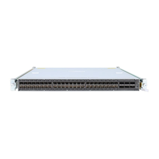
Product Overview The FM 2072 fabric module supports the HPE Composable Fabric through six QSFP+ ports in addition to supporting host and router devices through 48 SFP+ ports. Figure 1: FM 2072 Front Panel View For port details, included supported port speeds, see Front Panel SFP+ and QSFP+ Ports . Part Numbers The FM 2072 part number depends on the direction of air flow through the fabric module chassis (determined by the installed power supply and fan modules) and TAA compliance. -
Page 8: Checklist
Checklist Pre-staging Task Check/Comment Verify that redundant site power is available. Verify rack air flow. Verify equipment delivered. Record the MAC address of the fabric module. Determine the installation type: • In an HPE Composable Rack. • In another HPE environment. •... - Page 9 Task Check/Comment If you installed either a new fabric or a new fabric module to an existing fabric, perform a fit in the Composable Fabric Manager UI as described in HPE Composable Fabric Manager UI Online Help.. Carefully connect servers or other devices to access ports, one at a time, and in the Composable Fabric Manager UI, enabling each port as you install the connection and checking for any potential issues.
-
Page 10: Pre-Installation
Pre-Installation Verify Site Requirements Observe the following requirements when selecting a site to install the fabric module. Requirement Description Altitude The module is designed to operate at an altitude ranging from 0 to 5200 meters (0 to 10,000 feet). Ventilation To ensure proper ventilation, allow ample airflow to the front and back of the fabric module. -
Page 11: Verify Equipment Delivered
Verify Equipment Delivered Compare the contents of the shipment against the packing slip that was included in the shipment, check for any shipping damage, and verify that the components received match those ordered. Equipment Description Four hot swappable fans Installed in chassis. A blue bar indicates airflow from power supply panel to I/O panel. - Page 12 Item Description Power • Verify that power cords easily reach from the power outlets to the fabric module power supply modules. • Ensure that appropriate grounding and current surge protection are in place before connecting the fabric module to a power source. •...
-
Page 13: Installing Hpe Fm 2072
Procedure To install an HPE FM 2072 or FM 3180 fabric module that lacks center mounting holes in a rack: 1. Determine the 1-U slot position in the rack. IMPORTANT: You can mount the slides to the module in only one direction. So as to have all I/O cabling at the back of the rack, you will need to install the rails such that the fabric modules will be installed and removed through the back of the rack. -
Page 14: Using The Rack Mounting Assembly With Hinged Thumb Screw Bracket
There are two model-specific versions of the assembly (shown below) with the major difference between the two being the location of the chassis post mounting holes. FM 3132Q and FM 3032Q hinged rack mounting assembly Installing HPE FM 2072... - Page 15 Loosen the thumbscrew and pull the slide rail out until it stops. b. Push the rail release spring in to release the latch. c. Remove the slide rail. 3. Install the rack rails in the rack slot: Installing HPE FM 2072...
-
Page 16: Establishing A Management Connection
You can establish a management connection to the fabric module using either method: • Connect the console device to the Console port and establish a connection • Connect a management network to the MGMT port on the fabric module. Installing HPE FM 2072... -
Page 17: Establishing A Console Connection
When you connect one or both power supplies and provide site power to the fabric module, it automatically powers up. NOTE: There are two power supplies that should be connected to separate site power sources for redundancy. Installing HPE FM 2072... -
Page 18: Configuring The Fabric Module
Fabric using the Composable Fabric Manager UI as described in HPE Composable Fabric Manager UI Online Help. The UI contains the Guided Setup feature, which guides you through the process of adding a fabric to Composable Fabric Manager. Installing HPE FM 2072... -
Page 19: Overview: Network Port Cabling And Port Type
Overview: Network Port Cabling and Port Type The FM 2072 fabric module supports Composable Fabric connections and access connections from any of the SFP+ ports (1-48) or QSFP+ ports (49-54). However, you should follow the highly recommended fabric cabling as described in the chapters that follow. - Page 20 For information about changing the port type, refer to the Composable Fabric Manager UI online help (see the topic "Changing the Port Type"). Overview: Network Port Cabling and Port Type...
-
Page 21: Creating A Composable Fabric Using Fm 1006 Passive Interconnect Modules
Creating a Composable Fabric Using FM 1006 Passive Interconnect Modules You can create a network of four fabric modules or more by connecting Composable Fabric modules through FM 1006 passive interconnect modules. Using FM 1006 modules, you can create a network topology that includes FM 3180, FM 3132Q, FM 3032Q, FM 3180, FM 2072, and models 3eq, 2e, 2p, 2s and 2sp. -
Page 22: Fm 1006 Cabling Guidelines And Restrictions
Composable Fabric Ports: Twelve MPO24 ports to connect to as many as six fabric modules. The upper ports are • labeled E1 through E6 and the lower ports are labeled W1 through W6. You will connect E1 and W1 to one fabric module, E 2 and W2 to another fabric module, and so on. -
Page 23: Connecting Fabric Ports To An Fm 1006
Connecting Fabric Ports to an FM 1006 To connect a fabric module to an FM 1006, use two breakout (see Figure 2: FM1006 Fabric Interconnect Cable). The 3- connector side of the cable plugs into the three upper or lower highest-numbered fabric module QSFP+ ports. For example: Breakout Cable from FM 1006 port . -
Page 24: Expanding The Fabric Using Multiple Fm 1006 Devices
NOTE: All unused FM 1006 ports are looped back using loopback cables. Expanding the Fabric using Multiple FM 1006 Devices FM 1006 devices can be connected to expand the Composable Fabric. Three 24-fiber MTP cables are used to connect to an FM 1006 device to the next FM 1006 device, and an additional three cables are used to connect to the previous FM 1006 device. -
Page 25: Creating A Direct Connect Composable Fabric
Creating a Direct Connect Composable Fabric You can directly connect FM 2072 fabric modules using a QSFP+-to-QSFP+ cable such as DAC or AOC. You cannot directly connect FM 2072 fabric modules in a network that contains models 2, 2s, 2p or 2sp. You should not directly connect FM 2072 fabric modules in a network if the deployment is expected to grow beyond seven fabric modules. -
Page 26: Three-Module Fabric
From From Module 1 Module 2 Module 2 Module 1 Three-Module Fabric These are the connections to create a Composable Fabric consisting of three FM 2072 fabric modules. From From From Module 1 Module 2 Module 3 Module 2 50 Module 3 50 Module 1 50 Module 3 52... -
Page 27: Five-Module Fabric
From From From Module 1 Module 2 Module 3 Module 2 50 Module 3 50 Module 4 50 Module 3 52 Module 4 52 Module 1 52 Module 4 54 Module 1 54 Module 2 54 Module 4 Module 1 50 Module 2 52 Module 3 54 Five-Module Fabric... -
Page 28: Six-Module Fabric
From From From Module 1 Module 2 Module 3 Module 2 50 Module 3 50 Module 4 50 Module 3 52 Module 4 52 Module 5 52 Module 4 54 Module 5 54 Module 1 54 Module 4 Module 5 Module 5 50 Module 1 50 Module 1 52... -
Page 29: Seven Module Fabric
From From From Module 1 Module 2 Module 3 Module 2 50 Module 3 50 Module 4 50 Module 3 52 Module 4 52 Module 5 52 Module 4 54 Module 5 54 Module 6 54 Module 4 Module 5 Module 6 Module 5 50 Module 6 50... - Page 30 Begin with Module 1, then Module 2, and finish with the Module 7 connections to fabric modules 1, 2, and 3. From From From Module 1 Module 2 Module 3 Module 2 50 Module 3 50 Module 4 50 Module 3 52 Module 4 52 Module 5 52 Module 4 54...
- Page 31 From From From Module 2 52 Module 3 54 Creating a Direct Connect Composable Fabric...
-
Page 32: Adding A Module To An Existing Fabric
Adding a Module to an Existing Fabric Follow the guidelines described here to add a FM 2072 to an existing network. In preparation: • Identify the numbers or order of the current fabric modules in the fabric, which module is #1, which is #2, and so on. •... -
Page 33: Adding Module #5 To A Four-Module Fabric
You start changing connections with HPE FM 2072 module 3 port 53, then HPE FM 2072 module 4, next HPE FM 2072 module 5, and finally module 6. The following table lists the re-cabling required by direction. Cable Connection Steps to accomplish 1. -
Page 34: Adding Module #4 To A Three-Module Fabric
Cable Connection Steps to accomplish Module 4 49 to Module 5 50 1. Unplug Module 1 50 2. Plug freed end into Module 5 50 1. Unplug Module 3 54 Module 4 53 to Module 2 54 2. Plug freed end into Module 2 54 1. -
Page 35: Adding Module #3 To A Two-Module Fabric
Cable Connection Steps to accomplish Module 3 51 to Module 1 52 1. Unplug Module 2 52 2. Plug freed end into Module 1 52 1. Unplug Module 1 54 Module 3 53 to Module 2 54 2. Plug freed end into Module 2 54 Module 4 49 to Module 1 50 Plug Module 4 49 to Module 1 50 Module 4 51 to Module 2 52... -
Page 36: Installing Transceivers And Cables
Installing Transceivers and Cables For cables without a built-in transceiver, before you can connect the cables, you need to install the appropriate transceivers into the QSFP+ receptacles that need to be cabled. NOTE: Refer to the HPE Composable Fabric Support Matrix for supported cables and transceivers. Installing Transceivers For cables without a built-in transceiver, before you can connect the cables, you need to install the appropriate transceivers into the SFP+ or QSFP+ ports that need to be cabled. -
Page 37: Ports And Leds
Ports and LEDs Front Panel SFP+ and QSFP+ Ports The FM 2072 supports as many as 48 SFP+ transceivers and six QSFP+ transceivers. The following illustration identifies the FM 2072 front (I/O) panel ports for fabric and access connections: • 48 SFP+ ports 1-48 •... -
Page 38: Sfp+ And Qsfp+ Leds
QSFP Modes for QSFP+ 49-54 used as Fabric Ports in a Direct Connect Fabric QSFP+ #49-54 support the following QSFP modes when used as fabric ports in a direct connect fabric: • 1x40 GbE • 4x10 GbE QSFP Mode for QSFP+ 49-54 used as Fabric Ports in a Fabric Connected through FM 1006 Modules QSFP+ #49-54 support the following QSFP mode when used as fabric ports in a fabric connected through FM 1006 modules: 4x10 GbE... -
Page 39: Power Supply Led
State Lights when the SFP+-side power supply is plugged in (power supply labeled PWR1 located on opposite end). Lights when the QSFP+-side power supply is plugged in (power supply labeled PWR2 located on opposite end. STAT Operating status as follows: •... -
Page 40: Management Port Leds
Management Port LEDs The management port has two LEDs: • left one lights up when an active network is plugged in and flickers when there is activity • right one is unused. Ports and LEDs... -
Page 41: Hot Swap Fan And Power Modules
Hot Swap Fan and Power Modules An individual failed power module or fan module can be replaced by a customer network technician while the fabric module is powered up (hot swap) as described in this section. Replacing a Power Supply Module A single failed power supply module can be hot swapped as follows: Procedure 1. - Page 42 Procedure 1. Press the latches inward against the pull tabs and pull the fan module out of the fabric module chassis. 2. Insert the replacement fan module into the chassis slot until fully seated and the latches snap into place. NOTE: Each fan module is keyed to insure correct orientation.
-
Page 43: Fm 2072 Specifications
FM 2072 Specifications Component Value Chassis 1 RU form factor redundant Dimensions 1.73 inches high by 17.3 inches wide by 21.6 inches deep Weight 22.4 pounds (10.2 Kg) Power Consumption maximum: 520W, typical: 200W Altitude -60 to 5200 m Temperature 0-40C Humidity 10-90% non-condensing... -
Page 44: Support And Other Resources
Support and other resources Accessing Hewlett Packard Enterprise Support • For live assistance, go to the Contact Hewlett Packard Enterprise Worldwide website: https://www.hpe.com/info/assistance • To access documentation and support services, go to the Hewlett Packard Enterprise Support Center website: https://www.hpe.com/support/hpesc Information to collect •... -
Page 45: Customer Self Repair
Customer self repair Hewlett Packard Enterprise customer self repair (CSR) programs allow you to repair your product. If a CSR part needs to be replaced, it will be shipped directly to you so that you can install it at your convenience. Some parts do not qualify for CSR. -
Page 46: Websites
Websites General websites Hewlett Packard Enterprise Information Library https://www.hpe.com/info/EIL Single Point of Connectivity Knowledge (SPOCK) Storage compatibility matrix https://www.hpe.com/storage/spock Storage white papers and analyst reports https://www.hpe.com/storage/whitepapers For additional websites, see Support and other resources. Websites...
Need help?
Do you have a question about the HPE FM 2072 and is the answer not in the manual?
Questions and answers