Table of Contents

Related Manuals for Kampmann 148941


Summary of Contents for Kampmann 148941
- Page 1 Climate Controller Type 148941 (white) Type 148942 (black) Type 148943 (white with Modbus interface) Type 148944 (black with Modbus interface) User manual Keep these instructions in a safe place for future use! I589/08/20/ EN SAP-Nr. 1313436...
-
Page 2: Table Of Contents
Table of Contents ABOUT THESE INSTRUCTIONS ........................3 INTENDED USE ............................4 SAFETY INFORMATION..........................5 OPERATION OF THE CLIMATE CONTROLLER ..................... 6 ......................6 PERATION AND ISPLAY LEMENTS FUNCTIONALITY OF THE CLIMATE CONTROLLER ..................8 ............................8 ENERAL ............................8 ONTROL ........................ - Page 3 10.2 ........................29 ODBUS ARAMETER PARAMETER LIST ........................... 30...
-
Page 4: About These Instructions
1.96 Climate Controller Type 148941 / Type 148942 / Type 148943 / Type 148944 Operation manual 1 About these Instructions Carefully read these instructions in full prior to any assembly and installation work! Anyone involved with the installation, commissioning and use of this product is obliged to pass these instructions on to tradespeople who are involved at the same time or subsequently, as well as to end users or operators. -
Page 5: Intended Use
1.96 Climate Controller Type 148941 / Type 148942 / Type 148943 / Type 148944 Operation manual 2 Intended Use The Kampmann Climate Controller type 148941/ type 148942/ type 148943 and type 148944 has been designed in compliance with the state of the art and recognized safety-related regulations. -
Page 6: Safety Information
1.96 Climate Controller Type 148941 / Type 148942 / Type 148943 / Type 148944 Operation manual 3 Safety Information Only allow a qualified electrician to perform installation, assembly and maintenance work on electrical units in compliance with VDE guidelines. Wiring should comply with the applicable VDE regulations and provisions laid down by the regional electricity providers. -
Page 7: Operation Of The Climate Controller
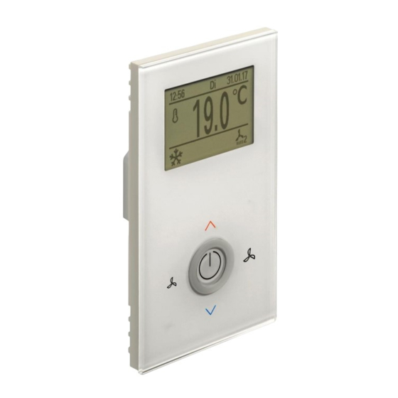
1.96 Climate Controller Type 148941 / Type 148942 / Type 148943 / Type 148944 Operation manual 4 Operation of the Climate Controller The Kampmann Climate Controller is a control unit with a high-quality glass surface for the control of secondary air equipment with EC fans and 2- or 4-pipe systems. - Page 8 1.96 Climate Controller Type 148941 / Type 148942 / Type 148943 / Type 148944 Operation manual 1. 2.5” LCD display 2. Header in the LCD 3. Main display in the LCD 4. Footer in the LCD 5. Raise setpoint temperature 6.
-
Page 9: Functionality Of The Climate Controller
1.96 Climate Controller Type 148941 / Type 148942 / Type 148943 / Type 148944 Operation manual 5 Functionality of the Climate Controller 5.1 General The type number of the Climate Controller is displayed on the start screen. The Climate Controller can be switched on and off using the On/Off key (9). - Page 10 1.96 Climate Controller Type 148941 / Type 148942 / Type 148943 / Type 148944 Operation manual 5.3.1 Temperature control in 4-pipe mode In 4-pipe mode, the controller automatically specifies the operating mode based on the room temperature and the setpoint inputted. The parameters: •...
- Page 11 1.96 Climate Controller Type 148941 / Type 148942 / Type 148943 / Type 148944 Operation manual 5.3.2 Temperature control in 2-pipe mode The operating mode can be defined according to the following functions in 2- pipe mode: • Changeover sensor •...
-
Page 12: Alarm Messages
1.96 Climate Controller Type 148941 / Type 148942 / Type 148943 / Type 148944 Operation manual 5.3.3 Temperature setting, relative value The temperature setpoint is inputted from the default view using keys (5) and (6). Do not perform an operation on the Climate Controller for 3 seconds to call up the default view. - Page 13 1.96 Climate Controller Type 148941 / Type 148942 / Type 148943 / Type 148944 Operation manual 6.1.2 A12 Motor protection The message "A12" appears in the display if a motor fault occurs. Cause: A digital input has been assigned the function ‘Motor fault’ and has...
- Page 14 1.96 Climate Controller Type 148941 / Type 148942 / Type 148943 / Type 148944 Operation manual 6.1.6 A16 Sensor faulty The sensor alarm is displayed if no plausible measured values are detected by an external sensor. Cause: There needs to be an external sensor configured as a room temperature sensor, intake sensor or changeover sensor and detect a temperature ≥...
-
Page 15: Timer Settings
1.96 Climate Controller Type 148941 / Type 148942 / Type 148943 / Type 148944 Operation manual 7 Timer Settings The user menu can be accessed by simultaneously pressing keys (5), (7) and (8) for a minimum of 3 seconds. Keys (5), (6), (7) and (8) can be used to navigate through the menu. The On/Off key confirms the adjustments performed. -
Page 16: Parameter Settings
1.96 Climate Controller Type 148941 / Type 148942 / Type 148943 / Type 148944 Operation manual 8 Parameter Settings Special system requirements can be configured using parameter settings in the Expert menu. The following system requirements are available: • Display •... -
Page 17: Fan Stages
1.96 Climate Controller Type 148941 / Type 148942 / Type 148943 / Type 148944 Operation manual 8.2 Fan Stages 8.2.1 General Number of stages 1 to 5 fan stages can be selected. The speed of each respective fan stage is calculated based on the number of fan stages. -
Page 18: Controller
1.96 Climate Controller Type 148941 / Type 148942 / Type 148943 / Type 148944 Operation manual 8.2.3 Heating threshold values Stage 1 Release of fan actuation up to 20% when the configured temperature is exceeded. Stage 2 Release of fan actuation up to 60% when the configured temperature is exceeded. -
Page 19: Inputs
1.96 Climate Controller Type 148941 / Type 148942 / Type 148943 / Type 148944 Operation manual Top: ECO mode is locked providing the presence message ‘occupied’ is showing. The following parameters can be adapted for heating mode: Type: A 2-point or PI controller can be selected as the control type. The PI controller can also be configured as a pure P controller. - Page 20 1.96 Climate Controller Type 148941 / Type 148942 / Type 148943 / Type 148944 Operation manual • Dewpoint contact • Presence contact • Key card switch • On / Off • Day / Eco • Condensation alarm • Unit frost protection •...
- Page 21 1.96 Climate Controller Type 148941 / Type 148942 / Type 148943 / Type 148944 Operation manual 8.4.7 Presence contact When the presence function is enabled, the heating setpoint is lowered by the ”Standby" parameter and the cooling setpoint is raised by the “Standby”...
-
Page 22: Outputs
1.96 Climate Controller Type 148941 / Type 148942 / Type 148943 / Type 148944 Operation manual 8.4.16 General error The parametrised input for the general error is continuously monitored and “A15” appears in the display if the input is activated to indicate that there is a general error. -
Page 23: Unit
1.96 Climate Controller Type 148941 / Type 148942 / Type 148943 / Type 148944 Operation manual 8.6 Unit General settings for the Climate Controller can be entered in ‘Unit Settings’. Status after Power On The Climate Controller assumes a defined state after the power supply has been switched on depending on this parameter. -
Page 24: Keys
1.96 Climate Controller Type 148941 / Type 148942 / Type 148943 / Type 148944 Operation manual 8.7.4 Setpoint adjustment The type of setpoint adjustment can be changed in this menu. Absolute Displays the absolute setpoint if the setpoint is changed by the temperature setting keys. -
Page 25: Installation
1.96 Climate Controller Type 148941 / Type 148942 / Type 148943 / Type 148944 Operation manual 9 Installation 9.1 Technical Data Measured variable Temperature Internal temperature sensor Measuring range: 0…+50 °C 0…10 V; max. 5 mA (EC fan actuation, max. cable length:... -
Page 26: Electrical Wiring
1.96 Climate Controller Type 148941 / Type 148942 / Type 148943 / Type 148944 Operation manual 9.3 Electrical Wiring Term. connection Type EC fan 0…10 V, max. 5 mA EC fan Output 2 230 V AC, max. 3A Output 1 230 V AC, max. -
Page 27: Climate Controller Versions And Accessories
1.96 Climate Controller Type 148941 / Type 148942 / Type 148943 / Type 148944 Operation manual Maximum cable lengths Total length between the Climate Controller and max. 30m the last unit Total length between the Climate Controller and max. 30m the ext. - Page 28 1.96 Climate Controller Type 148941 / Type 148942 / Type 148943 / Type 148944 Operation manual Figure Article Properties Article number Climate Controller with Modbus See Properties 196000148943 196000148944 interface, black Home temperature sensor, surface-mounted Temperature measuring range from -35°C to +70°C...
-
Page 29: Cabling Diagram
1.96 Climate Controller Type 148941 / Type 148942 / Type 148943 / Type 148944 Operation manual 9.6 Cabling Diagram Potential-free contact or external sensor Potential-free contact (type: 196000148941 & 196000148942) Modbus interface (type: 196000148943 & 196000148944) ** Contact 230 V... -
Page 30: Modbus Settings
1.96 Climate Controller Type 148941 / Type 148942 / Type 148943 / Type 148944 Operation manual 10 Modbus Settings 10.1 Modbus Interface Configuration To configure the Modbus interface, please open Modbus settings pressing simultaneously approximately 3 seconds. The modbus master interface and the climate control interface (as a slave) have to be adjusted equally. - Page 31 1.96 Climate Controller Type 148941 / Type 148942 / Type 148943 / Type 148944 Operation manual 11 Parameter List Default Menu Parameter Unit Comment setting Setpoints Base setpoint °C Adjustment range Increment Minimum °C Maximum °C Frost protection °C Heat protection °C...
- Page 32 1.96 Climate Controller Type 148941 / Type 148942 / Type 148943 / Type 148944 Operation manual Default Menu Parameter Unit Comment setting Eco / Day Disabled Unit frost protection Disabled Motor fault Disabled Filter alert Disabled Room frost protection Disabled...
- Page 33 1.96 Climate Controller Type 148941 / Type 148942 / Type 148943 / Type 148944 Operation manual Default Menu Parameter Unit Comment setting Motor fault Disabled Frost protection fault Disabled Unit frost protection fault Disabled Polarity Outputs/Output 2 Not used enabled...
- Page 34 1.96 Climate Controller Type 148941 / Type 148942 / Type 148943 / Type 148944 Operation manual Default Menu Parameter Unit Comment setting Sensor settings Internet offset -9.9 External offset -9.9 °C Unit °C °F Controller/General Hysteresis Start mode Auto Neutr. zone 4-p...
Need help?
Do you have a question about the 148941 and is the answer not in the manual?
Questions and answers