Table of Contents
Advertisement
Quick Links
KaController Typ 3210001, Typ 3210002, Typ 3210006
Fig. 1
Fig. 2
Type 3210001
1)
2)
3)
4)
Fig. 3
Fig. 4
Typ 3210001, 3210002, 3210006
Type 3210001, 3210002, 3210006
I385/02/10/1 INT
+0800016ED
KaController
Der KaController steuert die breite Angebotspalette der Kampmann-Systeme. Der KaController ist mit aktuellster Tech-
nologie ausgestattet und bietet dem Anwender die Möglichkeit, die Klimatisierung von Gebäuden den individuellen
Bedürfnissen anzupassen.
Mit dem großflächigen Display und der Ein-Knopf-Bedienung bietet der KaController höchsten Bedienkomfort.
Sicherheitshinweise
Installation und Montage sowie Wartungsarbeiten an elektrischen Geräten dürfen nur von einer Elektrofach-
kraft im Sinne der VDE durchgeführt werden. Der Anschluss ist gemäß den gültigen VDE-Bestimmungen und
den Richtlinien der EVU auszuführen.
Type 3210002
Bei Nichteinhaltung der Vorschriften und der Bedienungsanleitung können Funktionsstörungen mit Folge-
schäden und Personengefährdung entstehen. Bei Falschanschluss besteht durch Vertauschen der Drähte
Lebensgefahr!
Vor allen Anschluss- und Wartungsarbeiten sind alle Teile der Anlage spannungsfrei zu schalten und gegen
Wiedereinschalten zu sichern!
Unterputzdose
Für den KaController muss eine Unterputzdose installiert werden (siehe Abb. 4).
DIP-Schalter Einstellungen
Über die DIP-Schalter auf der Platine wird das Kommunikationsprotokoll eingestellt.
Zur Einstellung der DIP-Schalter ist das Bedienteil vom Basisgehäuse zu trennen. Die DIPSchalter befinden sich auf der
Rückseite des Bedienteils (siehe Fig.3).
Einstellungen der DIP-Schalter
DIP 1
DIP 2
OFF
OFF
ON
OFF
Uhrzeit / Zeitschaltprogramme
ON1
Montag
--:--
Dienstag
--:--
Mittwoch
--:--
Donnerstag
--:--
Freitag
--:--
Samstag
--:--
Sonntag
--:--
Werkseinstellung
Factory setting
Technische Daten
Spannungsversorgung
Schraubklemmen
Schutzart
Lagerungsbedingungen
Betriebsbedingungen
Abmessungen HxBxT
15
14
1
2
3
4
5
Displayanzeige
Alarme KaControl Gerät
Code
Alarme
A11
Regelfühler defekt
A12
Motorstörung
A13
Raumfrostschutz
A14
Kondensatalarm
A15
Genereller Alarm
A16
Fühler Al1, Al2 oder Al3 defekt
A17
Gerätefrostschutz
A18
EEPROM Fehler
A19
Slave offline im CAN-Bus-Netzwerk
Kommunikationsprotokoll
Werkseinstellung
Modbus
t-LAN
X
OFF1
ON1
OFF1
Die Uhrzeit wird in der Standard-
--:--
--:--
--:--
ansicht erst nach Einstellung der Uhr
--:--
--:--
--:--
im Menü „Zeiteinstellung" (siehe
--:--
--:--
--:--
Rückseite) eingeblendet.
Der KaController kann pro Tag 2 Ein- und
--:--
--:--
--:--
2 Ausschaltzeiten verwalten.
--:--
--:--
--:--
Die Eingabe der Ein- und Ausschaltzeiten
--:--
--:--
--:--
ist auf der Rückseite dargestellt.
--:--
--:--
--:--
24V AC/DC
Kabelquerschnitt: bis 1,5 mm
2
IP 30
-20–70 °C, Feuchte 10-90 % rF nicht kondensierend
0–60 °C, Feuchte 10-90 % rF nicht kondensierend
85 x 85 x 29 mm Wandaufbauhöhe (+30 mm Einbautiefe UP)
1
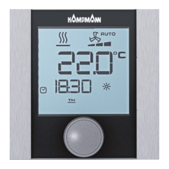
Anzeige Sollwert Raumtemperatur
13
12
11
Aktuelle Uhrzeit
2
Zeitschaltprogramm aktiv
3
4
Wochentag
5
Alarm
Angewählte Funktion ist gesperrt
6
10
Betriebsart Externe Ventilation aktiv
7
8
Filtermeldung
9
9
Ecobetrieb
Sollwerteinstellung aktiv
10
8
11
Vorgabe Lüfteransteuerung Auto-0-1-2-3-4-5
12
Betriebsart Lüften
Betriebsart Kühlen
6
7
13
Betriebsart Heizen
14
15
Betriebsart automatische Umschaltung
Heizen / Kühlen
Alarme KaController
Priorität
Code
Alarme
1
tAL1
Temperatursensor im KaController defekt
2
tAL3
Echtzeituhr im KaController defekt
3
tAL4
EEPROM im KaController defekt
4
Cn
Kommunikationsstörung mit der ext. Steuerung
5
6
7
8
9
KaController
The KaController controls the wide range of Kampmann systems. The KaController uses the latest technology and offers
users the possibility to adjust the air conditioning of buildings to individual needs.
The large display and the single button handling ensure a user-friendly navigation and maximum comfort.
Safety information
Installation, assembly and maintenance of electrical equipment should only be conducted by a qualified electri-
cian (Association of German Electricians approved or similar). Wiring should comply with the current Association
of German Electricians' (VDE) guidelines and regulations set out by the regional energy supply companies (EVU).
Non-observance of these guidelines and the operating manual can lead to malfunctions with subsequent
damage to the equipment and risk of personal injury. Incorrect wiring can result in fatal injury owing to
crossed wires!
Prior to all wiring and maintenance work, all parts of the system have to be made voltage-free and preven-
ted from being reconnected accidentally!
Flush-mounted back box
The KaController has to be installed in a flush-mounted back box (see 4)).
DIP switch settings
By using the DIP switches on the circuit board you can select the communication protocol.
To set the DIP switches you have to separate the control unit from the basic housing. You will find the DIP switches on
the back of the control unit (see fig.3).
DIP switch settings
DIP 1
DIP 2
Communication protocol
Modbus
OFF
OFF
ON
OFF
t-LAN
Time / Timer switching programmes
ON1
OFF1
ON1
OFF1
Monday
--:--
--:--
--:--
--:--
Tuesday
--:--
--:--
--:--
--:--
Wednesday
--:--
--:--
--:--
--:--
Thursday
--:--
--:--
--:--
--:--
Friday
--:--
--:--
--:--
--:--
Saturday
--:--
--:--
--:--
--:--
Sunday
--:--
--:--
--:--
--:--
Technical data
Voltage supply
24V AC/DC
Screw terminals
cable cross-section: up to 1,5 mm
2
Protection class
IP 30
Storage conditions
-20–70 °C, humidity 10-90% rel. humid. non-condensing
Operating conditions
0–60 °C, humidity 10-90% rel. humid. non-condensing
Dimensions HxWxD
85 x 85 x 29 mm surface-mounted height (+30 mm installation depth box)
1
Room temperature setpoint display
15
14
13
12
11
Current time
2
Active timer program
3
4
Weekday
5
Alarm
Selected function is locked
6
1
10
External Ventilation mode active
7
2
8
Filter message
3
9
9
Eco mode
4
Setpoint adjustment active
10
8
5
11
Auto-1-2-3-4-5 fan control target
12
Ventilation mode
Display
6
7
13
Cooling mode
Heating mode
14
15
Automatic heating/cooling changeover mode
Alarms KaControl unit
Alarms KaController
Code
Alarms
Priorität
Code
A11
Control sensor error
1
tAL1
A12
Fan error
2
tAL3
A13
Room frost protection
3
tAL4
A14
Condensate alarm
4
Cn
A15
General alarm
5
A16
Al1, Al2 or Al3 sensor error
6
A17
Unit frost protection
7
A18
EEPROM error
8
A19
Offline Slave in CANbus network
9
Kurzanleitung / Quick guide
Factory setting
X
The time will only be shown on the
Standard Display after the current
time has been set in the menu „time
setting" (see reverse).
The KaController can manage 2 turn-ON
times and 2 turn-OFF times per day.
The setting of the turn-ON and turn-Off
times is shown on the reverse.
Alarms
KaController Temperature sensor error
KaController real time clock error
KaController EEPROM error
Communication failure with the ext. control
Advertisement
Table of Contents

Related Manuals for Kampmann KaController


Summary of Contents for Kampmann KaController
- Page 1 Der KaController steuert die breite Angebotspalette der Kampmann-Systeme. Der KaController ist mit aktuellster Tech- The KaController controls the wide range of Kampmann systems. The KaController uses the latest technology and offers nologie ausgestattet und bietet dem Anwender die Möglichkeit, die Klimatisierung von Gebäuden den individuellen users the possibility to adjust the air conditioning of buildings to individual needs.
- Page 2 KaController Typ 3210001, Typ 3210002, Typ 3210006 Kurzanleitung / Quick guide Gerät Ausschalten Option 1: Drücken Sie den Navigator 3 Sek. Gerät Einschalten Option 2: Drücken Sie die ON/OFF Taste Option 1: Drücken Sie den Navigator Temperatursollwert einstellen Option 3: Drehen Sie den Navigator links herum bis OFF angezeigt wird Option 2: Drücken Sie die ON/OFF Taste...
Need help?
Do you have a question about the KaController and is the answer not in the manual?
Questions and answers